EP0134572A2 - Procédé pour l'aménagement d'un escalier de montage ainsi que l'escalier obtenu de cette façon - Google Patents
Procédé pour l'aménagement d'un escalier de montage ainsi que l'escalier obtenu de cette façon Download PDFInfo
- Publication number
- EP0134572A2 EP0134572A2 EP84110253A EP84110253A EP0134572A2 EP 0134572 A2 EP0134572 A2 EP 0134572A2 EP 84110253 A EP84110253 A EP 84110253A EP 84110253 A EP84110253 A EP 84110253A EP 0134572 A2 EP0134572 A2 EP 0134572A2
- Authority
- EP
- European Patent Office
- Prior art keywords
- spar
- elements
- assembly
- staircase
- connection
- Prior art date
- Legal status (The legal status is an assumption and is not a legal conclusion. Google has not performed a legal analysis and makes no representation as to the accuracy of the status listed.)
- Granted
Links
Images



Classifications
-
- E—FIXED CONSTRUCTIONS
- E04—BUILDING
- E04F—FINISHING WORK ON BUILDINGS, e.g. STAIRS, FLOORS
- E04F11/00—Stairways, ramps, or like structures; Balustrades; Handrails
- E04F11/02—Stairways; Layouts thereof
- E04F11/022—Stairways; Layouts thereof characterised by the supporting structure
- E04F11/035—Stairways consisting of a plurality of assembled modular parts without further support
Definitions
- the invention relates to a method for creating an assembly staircase from prefabricated components, which have at least one support beam, which is composed of individual spar elements, the spar elements are first inserted into each other in an adjustable and height-adjustable manner and are later fixed against each other.
- a cantilevered single-stage assembly staircase is already known, in which the assembly connections are provided between adjacent spar elements by means of fixable pin-socket arrangements.
- adjustment in the horizontal plane by twisting and height adjustment is possible before fixing the preassembled spar element in each case. It is then fixed in the area of the spigot-socket connection by means of clamping elements. If after the assembly of the staircase or its support spar there is still a position correction, be it simply because of the height and / or because of the spiral, the support spar must be dismantled and reassembled in a corrected form.
- the object of the present invention is to create a method of the type mentioned at the outset for creating an assembly staircase, in which in particular the amount of work required, in particular also in the case of necessary position corrections, is reduced and the staircase produced thereafter has great rigidity.
- the invention proposes, in particular, that the spar elements for forming a support spar first be brought into an assembly position that can be changed independently of one another at least in terms of height and rotation, then adjusted if necessary and then statically fixed to one another.
- a position adjustment can still be carried out well after the support spar has been created, and advantageously either the height or the angle of rotation (helix) can be adjusted independently of one another.
- the pre-assembly of the support bar can be carried out quickly and without complex re-measurements, so that overall a considerably shorter assembly time and a reduced effort are available.
- the individual spar elements are expediently first connected to one another in an adjustable manner with respect to one another using assembly aids, these assembly aids being removed after a static connection has been established between the spar elements.
- the auxiliary assembly elements allow spatially separate connections between adjacent spar elements, one connection being designed for a rotational movement and the other connection being designed for a vertical movement.
- the adjustment gaps provided between adjacent beam elements are filled, in particular cast, after the adjustment.
- a static connection is created after the casting compound or the like has hardened, which results in a firm bond between the individual spar elements.
- the assembly aids can then be removed.
- the invention also relates to a staircase produced by the method according to the invention, which can be assembled from prefabricated components and has at least one support spar which consists of individual spar elements which can be connected or connected to one another via plug-and-turn connections.
- the staircase according to the invention is characterized in particular in that, for connecting adjacent spar elements in a preassembly position, auxiliary mounting elements are provided which each have a height-adjustable connection on the one hand and a swivel connection for the adjacent spar elements on the other.
- the mounting aid elements in particular provide the possibility of readjusting the position of the individual spar elements after the entire spar has been created. The This can significantly reduce the amount of work.
- An expedient embodiment of the assembly aid element provides that it has an insertion pin as a swivel connection for a spar element and, on the other hand, connected to this insertion pin, height-adjustable connections for an adjacent spar element, a height support being located between adjacent spar elements, which is preferably arranged within the swivel joint.
- This configuration of the assembly aid element makes it possible on the one hand to have a stable connection, but on the other hand to adjust the height and angle of rotation independently of one another between adjacent spar elements.
- a favorable connection to the proposed shape of the spar elements is possible.
- the spar elements expediently have an approximately horizontal support part in the assembly position with a connecting opening and a connecting pin arranged at a distance from this opening and projecting over the top of the supporting part, the clear width of the connecting opening being dimensioned such that a space for adjusting movements is provided for an inserted connecting pin remains.
- this design does not yet result in a direct connection after adjacent spar elements have been plugged into one another, which is instead taken over by the mounting elements. Corresponding corrective movements of the individual spar elements via the connections of the assembly aid element are still possible.
- the A D closing spigot of the spar elements has an inner cavity open at the top for partially receiving the insertion spigot of the assembly aid element on.
- the spar element is pivotably connected to the mounting aid element in the horizontal plane.
- connections connected with insertion pins preferably have three approximately radially projecting holding arms which are provided at their free ends with approximately vertical openings for screws or the like to be connected with a spar element. These connections allow both height adjustment and alignment of the spar element held in a horizontal position.
- the basic contours of the insertion pins, the associated inner cavities and / or the connection opening in the spar elements are at least partially curved in a manner known per se in accordance with the course of the orthogonal trajectories of the main stress lines in the joint area.
- This structurally favorable shape results in rigid connections, so that the staircase as a whole has great rigidity even with a larger span.
- the connecting pin of the spar elements has a preferably cylindrical steel tube, or the like in accordance with the shape of the insertion pin, in particular by concrete. is formed.
- the steel tube results in a good stability of the connecting pin and is essentially used to secure against shear.
- this steel reinforcement provides the necessary connection stability between the steel pipe and the element body and at the same time also forms a reinforcement of the potting intermediate layer between the inner wall of the connection opening and the outside of the steel pipe after the static connection has been established.
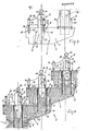
- a partially completed assembly staircase 1 shown in FIG. 1 consists of prefabricated components. Essentially, these are individual spar elements 2, which together form the support spar 3, and the steps 4.
- FIG. 1 part of a single-arm spiral staircase is shown.
- each spar element 2 has a support part 5 as the basic element of the element and a connecting pin 6 projecting above the top of the support part.
- the support part 5 has a connecting opening 7.
- the connecting pins 6 engage in the connection opening 7 of an adjacent spar element 2, which is higher in the exemplary embodiment.
- the connection opening 7 is dimensioned such that when the connecting pin 6 is inserted there is still a larger space 8 (FIG. 8), by means of which adjustment movements of adjacent spar elements 2 relative to one another are possible.
- assembly aid elements 9 are provided, which on the one hand have a height-adjustable connection 10 for Combine with the one spar element 2 and on the other hand a hinge connection 11 for connecting to the Benach - disclosed, having here below, other spar element.
- a height-adjustable connection 10 for Combine with the one spar element 2
- a hinge connection 11 for connecting to the Benach - disclosed, having here below, other spar element.
- FIGS. 3 and 4 show such a mounting aid element 9 in a top view or a side view. It essentially has an insertion pin 12 as a swivel joint and, on the other hand, connections connected to this insertion pin, which in the exemplary embodiment are designed as radially projecting holding arms 13.
- the holding arms 13 are attached to the upper end region of the insertion pin 12 and over a circumferential angle of z. B. 210 ° arranged.
- three holding arms 13 are provided, one in the mounting position (FIGS. 7 and 8) approximately in the central longitudinal plane direction of the support beam 3 and the other two approximately symmetrically to the side. This provides a three-point suspension, through which the respective spar element 2 is held well.
- connection of the holding arms 13 to the support part 5 of the spar element 2 is expediently carried out via screw connections, as shown in FIG. 7.
- approximately vertical push-through sleeves 14 for fastening screws 15 are provided at the ends of the holding arms 13. These are inserted from above through the push-through sleeves, secured on the underside if necessary by a lock nut 16 and in threaded sleeves 17 which are in the support part 5, screwed.
- the holding arms 13 with their outer attachment points are designed so that the insertion pin 12 of the auxiliary assembly element 9 is located approximately centrally within the connection opening 7 in the assembly position.
- connection pin 6 has an inner cavity 18 open at the top, into which the lower end of the insertion pin 12 of the assembly aid element 9 can be inserted. Due to the design of the plug-in pin and the inner cavity 18, it is possible to plug together up to a certain insertion depth, in which case the holding arms 13 still have an intended, underside distance from the spar element 2.
- the spar element 2 fastened to the holding arms 13 can thereby be rotated about the axis of rotation of the insertion pin 12 or of the connecting pin 6. This makes it possible to adapt the spar elements 2 to the winding provided in each case.
- the spar element 2 held can also be adjusted in its height by adjusting the fastening screws 15.
- the connecting pin 6 of the spar elements 2 has a cylindrical steel tube 19 which is connected to the support part 5 and has the inner cavity 18 on the inside.
- the inner cavity 18 is shaped in accordance with the shape of the lower end of the insertion pin 12 of the assembly aid element 9.
- Spar elements 2 preferably made of concrete, expediently consist of the formation within the steel tube 19 made of concrete, which enables simple manufacture.
- steel reinforcing bars are welded to the outside of the steel tube 19 in the region of its upper end, which also penetrate the support part 5. 6, these reinforcing bars 20 can be clearly seen, which are distributed in a cage shape around the steel tube 19. It can also be clearly seen here (cf. also FIG. 5) that these reinforcing bars 20 are guided at a distance from the steel pipe 19 approximately after their upper fastening point, approximately corresponding to the contour of the connection opening 7 (FIG. 8).
- the spar elements 2 are then statically fixed to one another. This is done by filling the intermediate joint between the connection opening 7 and the steel pipe 19, in particular, for example, pouring it with concrete.
- the reinforcement attached to the steel tube also forms a stabilizing connection due to its special arrangement, so that overall, after the filler material has hardened, a well-resilient connection between the spar elements 2 is created.
- the potting material 21 is identified by dots at two connection points.
- annular sealing inserts 22 are arranged at the lower end of the connecting openings 7, by means of which, when the intermediate space 8 is poured out, an underside, lateral escape of the potting material is prevented.
- the spar elements preferably consist essentially of reinforced concrete. This has besides good manufacturability and strength, in particular rigidity, the advantage that good fire safety is provided, so that use in buildings with higher storeys is also possible.
- a version made of metal, preferably cast aluminum is also possible, for example also for optical reasons.
- the steel tube 19 with its internal shape for the insertion pin 12 can also be designed as a prefabricated component. This simplifies the overall assembly of the spar element 2.
- such a connecting pin as well as the assembly aid element 9 can be used consistently for different spar element shapes.
- connection opening 7 into which the connecting pin 6 of an underlying spar element 2 projects in the installed position, also has a corresponding inner contour.
- the bar elements are at certain intervals, e.g. after four spar elements 2, supported by a support 24, as shown in Fig. 9.
- This support 24 is expediently steplessly adjustable in height by a screw connection 25 or the like to match the respective height of the spar element 2 to be supported.
- both the supports 24 and the auxiliary assembly elements 9 can be removed.
- a cantilevered support beam 3 is then optionally available, which can then be covered with steps 4 to complete the assembly staircase.
- the inner cavities 18 of the connecting pins 6 or also the connection points of the holding arms 13 can be used as fastening points for the assembly of the stair elements.
- the inner cavity 18 of the connecting pin 6 can also be used well for a temporary fastening, particularly for so-called structural stages 4 a.
- the basic stages 4 a have corresponding plug-in pins 12 a.
- wedges 26 can also be used on the rear end as an anti-rotation device.
- FIGS. 3, 4, 7 and 8 also show that the insertion pin 12 of the assembly aid element 9 carries a threaded rod 27 protruding at its lower end, which is connected to an abutment 29 at the upper end.
- the inner cavity 18 of the connecting pin 6, however, has at its inner end a nut 28 or the like.
- a twist-on molding is provided at the upper end of the threaded rod 27, here, for example, a twisting aid designed as a hooking eye 30 is provided at the same time.
- train connection is particularly necessary when mounting from top to bottom in order to give the spar element 2, which is mounted from below, a corresponding connection security.
- a train connection can be advantageous if the spar elements 2 provided with assembly aids 9 are transported, for example by means of a crane, from a storage location to the assembly site. It should also be mentioned that the auxiliary assembly elements 9 are removed after the static connection has been established between the individual spar elements 2 and are then available unchanged for further assemblies.
- the final steps 4 e.g. made of wood, natural stone, artificial stone, reinforced concrete, etc., already attached.
- the step securing takes place here via a mandrel 31 which engages in the spar element 2, in particular its connecting opening 7, and is mortared.
- steps 4 are preferably formed integrally on the spar elements.
- Such a staircase can preferably be used as an outside staircase.
Landscapes
- Engineering & Computer Science (AREA)
- Architecture (AREA)
- Civil Engineering (AREA)
- Structural Engineering (AREA)
- Steps, Ramps, And Handrails (AREA)
- Joining Of Building Structures In Genera (AREA)
Priority Applications (1)
| Application Number | Priority Date | Filing Date | Title |
|---|---|---|---|
| AT84110253T ATE36022T1 (de) | 1983-09-08 | 1984-08-29 | Verfahren zum erstellen einer montage-treppe sowie danach hergestellte treppe. |
Applications Claiming Priority (2)
| Application Number | Priority Date | Filing Date | Title |
|---|---|---|---|
| DE3332331 | 1983-09-08 | ||
| DE3332331A DE3332331A1 (de) | 1983-09-08 | 1983-09-08 | Verfahren zum erstellen einer montage-treppe sowie danach hergestellte treppe |
Publications (3)
| Publication Number | Publication Date |
|---|---|
| EP0134572A2 true EP0134572A2 (fr) | 1985-03-20 |
| EP0134572A3 EP0134572A3 (en) | 1985-12-04 |
| EP0134572B1 EP0134572B1 (fr) | 1988-07-27 |
Family
ID=6208500
Family Applications (1)
| Application Number | Title | Priority Date | Filing Date |
|---|---|---|---|
| EP84110253A Expired EP0134572B1 (fr) | 1983-09-08 | 1984-08-29 | Procédé pour l'aménagement d'un escalier de montage ainsi que l'escalier obtenu de cette façon |
Country Status (3)
| Country | Link |
|---|---|
| EP (1) | EP0134572B1 (fr) |
| AT (1) | ATE36022T1 (fr) |
| DE (2) | DE3332331A1 (fr) |
Cited By (3)
| Publication number | Priority date | Publication date | Assignee | Title |
|---|---|---|---|---|
| GB2179979A (en) * | 1985-09-06 | 1987-03-18 | Romulus Technology Ltd | Stair constructions |
| EP0859101A3 (fr) * | 1997-02-14 | 1998-10-21 | Werner Mühlberger | Escalier en porte-à-faux |
| CN111335563A (zh) * | 2020-04-16 | 2020-06-26 | 重庆渝高科技产业(集团)股份有限公司 | 一种全悬空多曲面异型扭弯钢结构楼梯 |
Families Citing this family (1)
| Publication number | Priority date | Publication date | Assignee | Title |
|---|---|---|---|---|
| DE4038722A1 (de) * | 1990-12-05 | 1992-06-11 | Neucon Masch Bausystem | Verfahren zum erstellen einer wangentreppe und wangentreppe nach dem verfahren |
Family Cites Families (6)
| Publication number | Priority date | Publication date | Assignee | Title |
|---|---|---|---|---|
| DE914547C (de) * | 1952-01-17 | 1954-07-05 | Wilhelm Geyer | Freitragende Steintreppe |
| AT270976B (de) * | 1965-02-16 | 1969-05-12 | Herbert Ernst | Montagefertige Treppe |
| DE1683539A1 (de) * | 1966-08-31 | 1971-02-11 | Wilhelm Schauffele | Natursteintreppenstufe |
| DE1910121A1 (de) * | 1969-02-28 | 1970-10-08 | Groetz Ernst | Bausatz fuer eine vorzugsweise zweiteilige Treppe |
| DE2065470A1 (de) * | 1970-02-09 | 1973-11-29 | Hans Stein | Abstandshalterung der trittplatten einer treppe |
| DE2626407A1 (de) * | 1976-06-12 | 1977-12-22 | Horst Walter Pollehn | Biegesteife steckverbindung zum verbinden von regal-, geruest-, tribuenen-, treppen- oder dergleichen bauteilen |
-
1983
- 1983-09-08 DE DE3332331A patent/DE3332331A1/de not_active Withdrawn
-
1984
- 1984-08-29 AT AT84110253T patent/ATE36022T1/de not_active IP Right Cessation
- 1984-08-29 EP EP84110253A patent/EP0134572B1/fr not_active Expired
- 1984-08-29 DE DE8484110253T patent/DE3472991D1/de not_active Expired
Cited By (4)
| Publication number | Priority date | Publication date | Assignee | Title |
|---|---|---|---|---|
| GB2179979A (en) * | 1985-09-06 | 1987-03-18 | Romulus Technology Ltd | Stair constructions |
| GB2179979B (en) * | 1985-09-06 | 1989-08-16 | Romulus Technology Ltd | Stair constructions |
| EP0859101A3 (fr) * | 1997-02-14 | 1998-10-21 | Werner Mühlberger | Escalier en porte-à-faux |
| CN111335563A (zh) * | 2020-04-16 | 2020-06-26 | 重庆渝高科技产业(集团)股份有限公司 | 一种全悬空多曲面异型扭弯钢结构楼梯 |
Also Published As
| Publication number | Publication date |
|---|---|
| EP0134572A3 (en) | 1985-12-04 |
| ATE36022T1 (de) | 1988-08-15 |
| DE3332331A1 (de) | 1985-03-28 |
| DE3472991D1 (en) | 1988-09-01 |
| EP0134572B1 (fr) | 1988-07-27 |
Similar Documents
| Publication | Publication Date | Title |
|---|---|---|
| DE1903129C3 (de) | Vorrichtung zum Anschließen eines Trägers an eine Betonstütze | |
| DE2840195C3 (de) | Vorrichtung zum Befestigen von zur Aufnahme von Brennelement-Bündeln dienenden Lagerkästen am Boden eines Wasserbeckens | |
| DE1807716B2 (de) | An den Längsseiten offenes, vorge fertigte s, transportables Raumelement zur Errichtung von Bauwerken der verschieden sten Art | |
| DE1910357A1 (de) | Tragstuetze,vorzugsweise zum Anbringen an Pfosten | |
| DE3129347A1 (de) | Verfahren zur vorfertigung und montage von dachbindern bzw. rahmenteilen aus stahlbeton sowie ein solcher dachbinder bzw. rahmenteil | |
| EP0134572B1 (fr) | Procédé pour l'aménagement d'un escalier de montage ainsi que l'escalier obtenu de cette façon | |
| WO2003006758A1 (fr) | Element de raccordement et procede de raccordement d'un composant en beton prefabrique a une partie d'un immeuble | |
| EP1338724B1 (fr) | Méthode pour ériger une construction comprenant un mur annulaire en béton | |
| DE9409626U1 (de) | Balkonkonstruktion | |
| DE3401906A1 (de) | Vorrichtung zur haengenden befestigung eines geruestelements | |
| DE2732183B2 (de) | Verbindung zweier mit ihren Stirnflächen einander gegenüberliegenden Stahlbetonteile | |
| EP1134331A2 (fr) | Ensemble d'éléments pour un coffrage | |
| DE9314567U1 (de) | Vorgefertigter Modul | |
| DE8908734U1 (de) | Turmschalung | |
| DE4234701C2 (de) | Verbindungsteil | |
| EP0645501A1 (fr) | Méthode pour la production de modules préfabriqués pour la construction de bâtiments et module préfabriqué | |
| DE29607590U1 (de) | Bausatz zur nachträglichen Erstellung eines Balkons | |
| DE19809127C2 (de) | Montagetreppe | |
| DE2427194A1 (de) | Spannbetonbalken und verfahren zu seiner herstellung | |
| EP0593017A1 (fr) | Pièce de raccordement | |
| DE2614186A1 (de) | Vorgefertigte schalung zur herstellung von ringankern an bauwerken | |
| DE29611012U1 (de) | Gitterstab zum Aufbau von Stabausfachungen | |
| DE7733030U1 (de) | Vorgefertigte montagetreppe | |
| DE2654807A1 (de) | Balkon | |
| DE4134139A1 (de) | Treppengelaender fuer montagetreppen |
Legal Events
| Date | Code | Title | Description |
|---|---|---|---|
| PUAI | Public reference made under article 153(3) epc to a published international application that has entered the european phase |
Free format text: ORIGINAL CODE: 0009012 |
|
| AK | Designated contracting states |
Designated state(s): AT BE CH DE FR GB LI SE |
|
| PUAL | Search report despatched |
Free format text: ORIGINAL CODE: 0009013 |
|
| AK | Designated contracting states |
Designated state(s): AT BE CH DE FR GB LI SE |
|
| 17P | Request for examination filed |
Effective date: 19851210 |
|
| 17Q | First examination report despatched |
Effective date: 19860730 |
|
| R17C | First examination report despatched (corrected) |
Effective date: 19870205 |
|
| GRAA | (expected) grant |
Free format text: ORIGINAL CODE: 0009210 |
|
| AK | Designated contracting states |
Kind code of ref document: B1 Designated state(s): AT BE CH DE FR GB LI SE |
|
| REF | Corresponds to: |
Ref document number: 36022 Country of ref document: AT Date of ref document: 19880815 Kind code of ref document: T |
|
| REF | Corresponds to: |
Ref document number: 3472991 Country of ref document: DE Date of ref document: 19880901 |
|
| GBT | Gb: translation of ep patent filed (gb section 77(6)(a)/1977) | ||
| ET | Fr: translation filed | ||
| PLBE | No opposition filed within time limit |
Free format text: ORIGINAL CODE: 0009261 |
|
| STAA | Information on the status of an ep patent application or granted ep patent |
Free format text: STATUS: NO OPPOSITION FILED WITHIN TIME LIMIT |
|
| 26N | No opposition filed | ||
| PGFP | Annual fee paid to national office [announced via postgrant information from national office to epo] |
Ref country code: FR Payment date: 19940812 Year of fee payment: 11 |
|
| PGFP | Annual fee paid to national office [announced via postgrant information from national office to epo] |
Ref country code: SE Payment date: 19940815 Year of fee payment: 11 |
|
| PGFP | Annual fee paid to national office [announced via postgrant information from national office to epo] |
Ref country code: GB Payment date: 19940824 Year of fee payment: 11 |
|
| PGFP | Annual fee paid to national office [announced via postgrant information from national office to epo] |
Ref country code: AT Payment date: 19940831 Year of fee payment: 11 |
|
| PGFP | Annual fee paid to national office [announced via postgrant information from national office to epo] |
Ref country code: BE Payment date: 19941005 Year of fee payment: 11 |
|
| EAL | Se: european patent in force in sweden |
Ref document number: 84110253.6 |
|
| PG25 | Lapsed in a contracting state [announced via postgrant information from national office to epo] |
Ref country code: GB Effective date: 19950829 Ref country code: AT Effective date: 19950829 |
|
| PG25 | Lapsed in a contracting state [announced via postgrant information from national office to epo] |
Ref country code: SE Effective date: 19950830 |
|
| PG25 | Lapsed in a contracting state [announced via postgrant information from national office to epo] |
Ref country code: BE Effective date: 19950831 |
|
| BERE | Be: lapsed |
Owner name: POLLEHN HORST WALTER Effective date: 19950831 |
|
| GBPC | Gb: european patent ceased through non-payment of renewal fee |
Effective date: 19950829 |
|
| PG25 | Lapsed in a contracting state [announced via postgrant information from national office to epo] |
Ref country code: FR Effective date: 19960430 |
|
| EUG | Se: european patent has lapsed |
Ref document number: 84110253.6 |
|
| REG | Reference to a national code |
Ref country code: FR Ref legal event code: ST |
|
| PGFP | Annual fee paid to national office [announced via postgrant information from national office to epo] |
Ref country code: DE Payment date: 19960710 Year of fee payment: 13 |
|
| PGFP | Annual fee paid to national office [announced via postgrant information from national office to epo] |
Ref country code: CH Payment date: 19970910 Year of fee payment: 14 |
|
| PG25 | Lapsed in a contracting state [announced via postgrant information from national office to epo] |
Ref country code: DE Free format text: LAPSE BECAUSE OF NON-PAYMENT OF DUE FEES Effective date: 19980501 |
|
| PG25 | Lapsed in a contracting state [announced via postgrant information from national office to epo] |
Ref country code: LI Free format text: LAPSE BECAUSE OF NON-PAYMENT OF DUE FEES Effective date: 19980831 Ref country code: CH Free format text: LAPSE BECAUSE OF NON-PAYMENT OF DUE FEES Effective date: 19980831 |
|
| REG | Reference to a national code |
Ref country code: CH Ref legal event code: PL |