EP0134646A1 - Steuersystem für automatische Fahrzeuggetriebe - Google Patents
Steuersystem für automatische Fahrzeuggetriebe Download PDFInfo
- Publication number
- EP0134646A1 EP0134646A1 EP84304496A EP84304496A EP0134646A1 EP 0134646 A1 EP0134646 A1 EP 0134646A1 EP 84304496 A EP84304496 A EP 84304496A EP 84304496 A EP84304496 A EP 84304496A EP 0134646 A1 EP0134646 A1 EP 0134646A1
- Authority
- EP
- European Patent Office
- Prior art keywords
- gear
- gear position
- switch
- selection
- shift
- Prior art date
- Legal status (The legal status is an assumption and is not a legal conclusion. Google has not performed a legal analysis and makes no representation as to the accuracy of the status listed.)
- Granted
Links
Images





Classifications
-
- F—MECHANICAL ENGINEERING; LIGHTING; HEATING; WEAPONS; BLASTING
- F16—ENGINEERING ELEMENTS AND UNITS; GENERAL MEASURES FOR PRODUCING AND MAINTAINING EFFECTIVE FUNCTIONING OF MACHINES OR INSTALLATIONS; THERMAL INSULATION IN GENERAL
- F16H—GEARING
- F16H61/00—Control functions within control units of change-speed- or reversing-gearings for conveying rotary motion ; Control of exclusively fluid gearing, friction gearing, gearings with endless flexible members or other particular types of gearing
- F16H61/12—Detecting malfunction or potential malfunction, e.g. fail safe ; Circumventing or fixing failures
-
- F—MECHANICAL ENGINEERING; LIGHTING; HEATING; WEAPONS; BLASTING
- F16—ENGINEERING ELEMENTS AND UNITS; GENERAL MEASURES FOR PRODUCING AND MAINTAINING EFFECTIVE FUNCTIONING OF MACHINES OR INSTALLATIONS; THERMAL INSULATION IN GENERAL
- F16H—GEARING
- F16H59/00—Control inputs to control units of change-speed- or reversing-gearings for conveying rotary motion
-
- B—PERFORMING OPERATIONS; TRANSPORTING
- B60—VEHICLES IN GENERAL
- B60W—CONJOINT CONTROL OF VEHICLE SUB-UNITS OF DIFFERENT TYPE OR DIFFERENT FUNCTION; CONTROL SYSTEMS SPECIALLY ADAPTED FOR HYBRID VEHICLES; ROAD VEHICLE DRIVE CONTROL SYSTEMS FOR PURPOSES NOT RELATED TO THE CONTROL OF A PARTICULAR SUB-UNIT
- B60W10/00—Conjoint control of vehicle sub-units of different type or different function
- B60W10/02—Conjoint control of vehicle sub-units of different type or different function including control of driveline clutches
-
- B—PERFORMING OPERATIONS; TRANSPORTING
- B60—VEHICLES IN GENERAL
- B60W—CONJOINT CONTROL OF VEHICLE SUB-UNITS OF DIFFERENT TYPE OR DIFFERENT FUNCTION; CONTROL SYSTEMS SPECIALLY ADAPTED FOR HYBRID VEHICLES; ROAD VEHICLE DRIVE CONTROL SYSTEMS FOR PURPOSES NOT RELATED TO THE CONTROL OF A PARTICULAR SUB-UNIT
- B60W10/00—Conjoint control of vehicle sub-units of different type or different function
- B60W10/10—Conjoint control of vehicle sub-units of different type or different function including control of change-speed gearings
- B60W10/11—Stepped gearings
-
- B—PERFORMING OPERATIONS; TRANSPORTING
- B60—VEHICLES IN GENERAL
- B60W—CONJOINT CONTROL OF VEHICLE SUB-UNITS OF DIFFERENT TYPE OR DIFFERENT FUNCTION; CONTROL SYSTEMS SPECIALLY ADAPTED FOR HYBRID VEHICLES; ROAD VEHICLE DRIVE CONTROL SYSTEMS FOR PURPOSES NOT RELATED TO THE CONTROL OF A PARTICULAR SUB-UNIT
- B60W30/00—Purposes of road vehicle drive control systems not related to the control of a particular sub-unit, e.g. of systems using conjoint control of vehicle sub-units
- B60W30/18—Propelling the vehicle
-
- B—PERFORMING OPERATIONS; TRANSPORTING
- B60—VEHICLES IN GENERAL
- B60W—CONJOINT CONTROL OF VEHICLE SUB-UNITS OF DIFFERENT TYPE OR DIFFERENT FUNCTION; CONTROL SYSTEMS SPECIALLY ADAPTED FOR HYBRID VEHICLES; ROAD VEHICLE DRIVE CONTROL SYSTEMS FOR PURPOSES NOT RELATED TO THE CONTROL OF A PARTICULAR SUB-UNIT
- B60W50/00—Details of control systems for road vehicle drive control not related to the control of a particular sub-unit, e.g. process diagnostic or vehicle driver interfaces
- B60W50/02—Ensuring safety in case of control system failures, e.g. by diagnosing, circumventing or fixing failures
- B60W50/0205—Diagnosing or detecting failures; Failure detection models
-
- F—MECHANICAL ENGINEERING; LIGHTING; HEATING; WEAPONS; BLASTING
- F16—ENGINEERING ELEMENTS AND UNITS; GENERAL MEASURES FOR PRODUCING AND MAINTAINING EFFECTIVE FUNCTIONING OF MACHINES OR INSTALLATIONS; THERMAL INSULATION IN GENERAL
- F16H—GEARING
- F16H59/00—Control inputs to control units of change-speed- or reversing-gearings for conveying rotary motion
- F16H59/68—Inputs being a function of gearing status
- F16H59/70—Inputs being a function of gearing status dependent on the ratio established
-
- B—PERFORMING OPERATIONS; TRANSPORTING
- B60—VEHICLES IN GENERAL
- B60W—CONJOINT CONTROL OF VEHICLE SUB-UNITS OF DIFFERENT TYPE OR DIFFERENT FUNCTION; CONTROL SYSTEMS SPECIALLY ADAPTED FOR HYBRID VEHICLES; ROAD VEHICLE DRIVE CONTROL SYSTEMS FOR PURPOSES NOT RELATED TO THE CONTROL OF A PARTICULAR SUB-UNIT
- B60W2510/00—Input parameters relating to a particular sub-units
- B60W2510/02—Clutches
- B60W2510/0208—Clutch engagement state, e.g. engaged or disengaged
-
- B—PERFORMING OPERATIONS; TRANSPORTING
- B60—VEHICLES IN GENERAL
- B60W—CONJOINT CONTROL OF VEHICLE SUB-UNITS OF DIFFERENT TYPE OR DIFFERENT FUNCTION; CONTROL SYSTEMS SPECIALLY ADAPTED FOR HYBRID VEHICLES; ROAD VEHICLE DRIVE CONTROL SYSTEMS FOR PURPOSES NOT RELATED TO THE CONTROL OF A PARTICULAR SUB-UNIT
- B60W2510/00—Input parameters relating to a particular sub-units
- B60W2510/06—Combustion engines, Gas turbines
- B60W2510/0638—Engine speed
-
- B—PERFORMING OPERATIONS; TRANSPORTING
- B60—VEHICLES IN GENERAL
- B60W—CONJOINT CONTROL OF VEHICLE SUB-UNITS OF DIFFERENT TYPE OR DIFFERENT FUNCTION; CONTROL SYSTEMS SPECIALLY ADAPTED FOR HYBRID VEHICLES; ROAD VEHICLE DRIVE CONTROL SYSTEMS FOR PURPOSES NOT RELATED TO THE CONTROL OF A PARTICULAR SUB-UNIT
- B60W2520/00—Input parameters relating to overall vehicle dynamics
- B60W2520/10—Longitudinal speed
-
- B—PERFORMING OPERATIONS; TRANSPORTING
- B60—VEHICLES IN GENERAL
- B60W—CONJOINT CONTROL OF VEHICLE SUB-UNITS OF DIFFERENT TYPE OR DIFFERENT FUNCTION; CONTROL SYSTEMS SPECIALLY ADAPTED FOR HYBRID VEHICLES; ROAD VEHICLE DRIVE CONTROL SYSTEMS FOR PURPOSES NOT RELATED TO THE CONTROL OF A PARTICULAR SUB-UNIT
- B60W2540/00—Input parameters relating to occupants
- B60W2540/10—Accelerator pedal position
-
- B—PERFORMING OPERATIONS; TRANSPORTING
- B60—VEHICLES IN GENERAL
- B60W—CONJOINT CONTROL OF VEHICLE SUB-UNITS OF DIFFERENT TYPE OR DIFFERENT FUNCTION; CONTROL SYSTEMS SPECIALLY ADAPTED FOR HYBRID VEHICLES; ROAD VEHICLE DRIVE CONTROL SYSTEMS FOR PURPOSES NOT RELATED TO THE CONTROL OF A PARTICULAR SUB-UNIT
- B60W2710/00—Output or target parameters relating to a particular sub-units
- B60W2710/10—Change speed gearings
- B60W2710/1005—Transmission ratio engaged
-
- F—MECHANICAL ENGINEERING; LIGHTING; HEATING; WEAPONS; BLASTING
- F16—ENGINEERING ELEMENTS AND UNITS; GENERAL MEASURES FOR PRODUCING AND MAINTAINING EFFECTIVE FUNCTIONING OF MACHINES OR INSTALLATIONS; THERMAL INSULATION IN GENERAL
- F16H—GEARING
- F16H59/00—Control inputs to control units of change-speed- or reversing-gearings for conveying rotary motion
- F16H59/68—Inputs being a function of gearing status
- F16H2059/6807—Status of gear-change operation, e.g. clutch fully engaged
-
- F—MECHANICAL ENGINEERING; LIGHTING; HEATING; WEAPONS; BLASTING
- F16—ENGINEERING ELEMENTS AND UNITS; GENERAL MEASURES FOR PRODUCING AND MAINTAINING EFFECTIVE FUNCTIONING OF MACHINES OR INSTALLATIONS; THERMAL INSULATION IN GENERAL
- F16H—GEARING
- F16H59/00—Control inputs to control units of change-speed- or reversing-gearings for conveying rotary motion
- F16H59/68—Inputs being a function of gearing status
- F16H59/70—Inputs being a function of gearing status dependent on the ratio established
- F16H2059/706—Monitoring gear ratio in stepped transmissions, e.g. by calculating the ratio from input and output speed
-
- F—MECHANICAL ENGINEERING; LIGHTING; HEATING; WEAPONS; BLASTING
- F16—ENGINEERING ELEMENTS AND UNITS; GENERAL MEASURES FOR PRODUCING AND MAINTAINING EFFECTIVE FUNCTIONING OF MACHINES OR INSTALLATIONS; THERMAL INSULATION IN GENERAL
- F16H—GEARING
- F16H61/00—Control functions within control units of change-speed- or reversing-gearings for conveying rotary motion ; Control of exclusively fluid gearing, friction gearing, gearings with endless flexible members or other particular types of gearing
- F16H61/12—Detecting malfunction or potential malfunction, e.g. fail safe ; Circumventing or fixing failures
- F16H2061/1208—Detecting malfunction or potential malfunction, e.g. fail safe ; Circumventing or fixing failures with diagnostic check cycles; Monitoring of failures
-
- F—MECHANICAL ENGINEERING; LIGHTING; HEATING; WEAPONS; BLASTING
- F16—ENGINEERING ELEMENTS AND UNITS; GENERAL MEASURES FOR PRODUCING AND MAINTAINING EFFECTIVE FUNCTIONING OF MACHINES OR INSTALLATIONS; THERMAL INSULATION IN GENERAL
- F16H—GEARING
- F16H61/00—Control functions within control units of change-speed- or reversing-gearings for conveying rotary motion ; Control of exclusively fluid gearing, friction gearing, gearings with endless flexible members or other particular types of gearing
- F16H61/12—Detecting malfunction or potential malfunction, e.g. fail safe ; Circumventing or fixing failures
- F16H2061/122—Avoiding failures by using redundant parts
-
- F—MECHANICAL ENGINEERING; LIGHTING; HEATING; WEAPONS; BLASTING
- F16—ENGINEERING ELEMENTS AND UNITS; GENERAL MEASURES FOR PRODUCING AND MAINTAINING EFFECTIVE FUNCTIONING OF MACHINES OR INSTALLATIONS; THERMAL INSULATION IN GENERAL
- F16H—GEARING
- F16H61/00—Control functions within control units of change-speed- or reversing-gearings for conveying rotary motion ; Control of exclusively fluid gearing, friction gearing, gearings with endless flexible members or other particular types of gearing
- F16H61/12—Detecting malfunction or potential malfunction, e.g. fail safe ; Circumventing or fixing failures
- F16H2061/1256—Detecting malfunction or potential malfunction, e.g. fail safe ; Circumventing or fixing failures characterised by the parts or units where malfunctioning was assumed or detected
- F16H2061/1284—Detecting malfunction or potential malfunction, e.g. fail safe ; Circumventing or fixing failures characterised by the parts or units where malfunctioning was assumed or detected the failing part is a sensor
-
- F—MECHANICAL ENGINEERING; LIGHTING; HEATING; WEAPONS; BLASTING
- F16—ENGINEERING ELEMENTS AND UNITS; GENERAL MEASURES FOR PRODUCING AND MAINTAINING EFFECTIVE FUNCTIONING OF MACHINES OR INSTALLATIONS; THERMAL INSULATION IN GENERAL
- F16H—GEARING
- F16H61/00—Control functions within control units of change-speed- or reversing-gearings for conveying rotary motion ; Control of exclusively fluid gearing, friction gearing, gearings with endless flexible members or other particular types of gearing
- F16H61/68—Control functions within control units of change-speed- or reversing-gearings for conveying rotary motion ; Control of exclusively fluid gearing, friction gearing, gearings with endless flexible members or other particular types of gearing specially adapted for stepped gearings
- F16H61/682—Control functions within control units of change-speed- or reversing-gearings for conveying rotary motion ; Control of exclusively fluid gearing, friction gearing, gearings with endless flexible members or other particular types of gearing specially adapted for stepped gearings with interruption of drive
-
- Y—GENERAL TAGGING OF NEW TECHNOLOGICAL DEVELOPMENTS; GENERAL TAGGING OF CROSS-SECTIONAL TECHNOLOGIES SPANNING OVER SEVERAL SECTIONS OF THE IPC; TECHNICAL SUBJECTS COVERED BY FORMER USPC CROSS-REFERENCE ART COLLECTIONS [XRACs] AND DIGESTS
- Y10—TECHNICAL SUBJECTS COVERED BY FORMER USPC
- Y10S—TECHNICAL SUBJECTS COVERED BY FORMER USPC CROSS-REFERENCE ART COLLECTIONS [XRACs] AND DIGESTS
- Y10S477/00—Interrelated power delivery controls, including engine control
- Y10S477/906—Means detecting or ameliorating the effects of malfunction or potential malfunction
Definitions
- the present invention relates to a diagnostic processing system and method for an automatic transmission in a vehicle such as an automobile.
- the present invention refers to that wherein the automatic transmission is basically composed of members identical to those incorporated in usual manually operated transmission, i.e. clutch -and slidable-mesh gear transmissions, but in which these members are controlled by a microprocessor in response to relevant data recieved, such as an accelerator position signal, automobile speed signal, etc.
- Automobile transmissions should operate with a high degree of reliability, and various systems have been proposed to attain this high reliability. However, none of these systems have yet attained the required reliability with respect to the aforementioned type of automatic transmission.
- a method of controlling an automatic transmission of a vehicle comprises determining information relating to at least the rotation speed (a) of an input shaft, a vehicle speed (a), an N/V ratio, an accelerator position, a clutch position, an engine speed, and a gear selection; generating an actuation signal to control the transmission in accordance with at least some of the determined information; and determining whether or not a gear change is completed by analysing the determined gear selection together with the input shaft rotation speed (a) and the vehicle speed (8).
- a diagnostic processing system for an automatic transmission of a vehicle including transmission gears and a clutch which are both activated by means of individual actuators under the control of a control unit which produces an actuation signal for the actuators, with reference to a predetermined transmission map, in response to a variety of input data representing, at least, a rotation speed (a) of an input-shaft, a vehicle speed ( ⁇ ), an N/V ratio, an accelerator pedal position, a clutch position, and an engine speed, comprises a gear position sensor cooperating with the transmission gears, and the control unit being operative to judge a gear position of the transmission gears based on the gear position signals output from the gear position sensor and determining whether or not each gear change is completed by analysing the judged gear position and the input data representing the rotation speed (a) and the vehicle speed (8).
- the present invention provides a method and system which will attain a high reliability of the automatic transmission provided in a vehicle such as an automobile.
- the diagnostic processing system of the present invention cooperates with the automatic transmission of an automobile through the innovation of the gear position sensor.
- the gear position sensor is useful for electronic controlled automatic transmission, in that the sensor is used for detecting, among a plurality of gear positions, which gear position is operable at any given moment.
- the present invention specifically refers to various factors to be checked through a diagnositc process, such as completion of a gear-out operation, completion of a gear-in operation, completion of a gear change, and if the sensor is operating normally. Further, if the sensor operation is abnormal, the system magy instigate a support backup for the sensor.
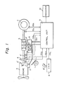
- Figure 1 is a schematic block diagram of a known electronic controlled automatic transmission provided in a body of an automobile.
- the present invention can be applied to an automobile having a constructian as shown in Fig. 1. That is, a usual clutch and sliding-mesh : type transmission gears are actuated by respective actuators under the control of a control unit, in which a conventional torque-converter and auxiliary subtransmission are not used.
- a control unit in which a conventional torque-converter and auxiliary subtransmission are not used.
- reference numeral 1 represents an accelerator pedal, 2 a throttle actuator for adjusting a throttle valve 2', 3 an engine, 4 a clutch, 5 transmission gears, 6 solenoid valves for driving a clutch actuator 4' and a transmission actuator 5', 7 a drive wheel, 8 a mode selector provided with a select lever 8', for manually selecting a drive mode such as drive (D), neutral (N), and reverse (R), 9 a control unit, constituted by a microprocessor, for controlling the throttle actuator 2, the solenoid valves 6, and producing a hill start aid output (HSA), and 10 an indicator for displaying the present gear position of the transmission 5.
- HSA hill start aid output
- the control unit 9 receives, at respective.input ports, a lever position signal PS L from the selector 8, an accelerator position signal PS A from the accelerator pedal 1, i.e., throttle angle signal, an engine speed indication signal IS E from the output side of the engine 3, a clutch position signal PS C from the clutch 4, a rotational input-shaft speed indication signal IS S , and an automobile speed indication signal IS A , etc.
- a lever position signal PS L from the selector 8 an accelerator position signal PS A from the accelerator pedal 1, i.e., throttle angle signal, an engine speed indication signal IS E from the output side of the engine 3, a clutch position signal PS C from the clutch 4, a rotational input-shaft speed indication signal IS S , and an automobile speed indication signal IS A , etc.
- the above-mentioned input signals PSL , PS A , PS C , IS E , IS S , and so on are detected by and produced from individual suitable sensors. These sensors are widely known per se.
- the control unit 9 receives and processes the individual input signals from these sensors to produce output signals at the respective output ports, thereby controlling the engine speed through the throttle actuator 2, engagement or disengagement of the clutch 4 through the clutch actuator 4', and gear changes in the transmssion 5 through the transmission actuator 5'.
- the engagement or disengagement of the clutch 4 is determined by an instruction element of the control unit 9 in response to the engine speed indication signal IS E and the rotational input-shaft speed indication signal IS S .
- the gear change in the transmission is controlled in response to the accelerator position signal PS A , indicative of the throttle angle, and the engine speed indication signal IS E , with reference to a transmission map (Fig. 2).
- Figure 2 is a schematic diagram of a map used for determining a suitable gear position.
- the map determines a gear position best suited for the running of the automobile in accordance with the throttle angle TH, in %, and the automobile speed AS in km/h.
- a TH of 100% represents a state in which the throttle valve is fully opened, while a TH of 0% represents a state in which the throttle valve is closed.
- numerals 1, 2, 3, 4, and 5 denote individual gear positions.
- the curves indicated by solid lines represent gear change borders during acceleration, while the curves indicated by broken lines represent gear change borders during deceleration, with reference to Fig.
- the system of the present invention operates to supervise the conditions of the clutch 4, transmission gears 5, and so on, as shown in Fig. 1, and to this end a gear position sensor 21 (Fig. 3) is introduced into the system.
- Figure 3 is a schematic circuit diagram of a gear position sensor and its peripheral members.
- the gear position sensor is generally represented by reference numeral 21.
- the gear position sensor 21 is located in the transmission gears box 5 (Fig. 1) and constituted by gear position switches G12, G34, G5R, G135, GN, and G24R. Data giving the on/off state of each gear position switch is stored in 8-bit buffer registers BF 1 and BF 2 .
- Encircled reference numerals 1 through 5 of Fig. 3 denote first through fifth gear positions, respectively.
- Encircled R denotes the reverse gear position.
- the gear position to be selected is determined by the gear position switches (G). These switches (G) are classified as shift-side switches G135, GN, and G24R, and selection-side switches G12, G34, and G5R. Data giving the on/off state of these switches is stored, as mentioned before, in the buffer registers BF 1 and BF 2 , both of which can be formed as an element of the microprocessor, i.e., the control unit 9 of Fig. 1. When one of the first, third and fifth gear positions is selected, the switch G135 is turned on.
- the actuator of the switch G13 can be mechanically actuated by the selected transmission gear 5 (Fig. 1) (this also applies to switches GN, G24R).
- the switch GN When the transmission is set at the neutral_gear position, the switch GN is turned on.
- the switch G24R is turned on.
- the switch G12 when one of the first and second gear positions and the neutral gear position N1 is selected, the switch G12 is turned on.
- the actuator of the switch G12 can be mechanically actuated by the selected transmission gear 5 (Fig. 1) (this also applies to switches G34 and G5R).
- the switch G34 When one of the third and fourth gear positions and the neutral gear position N2 is selected, the switch G34 is turned on.
- the switch G5R When one of the fifth gear position, the neutral gear position N3, and the reverse gear position is selected, the switch G5R is turned on.
- the microprocessor can determine that the fifth gear position is actually selected at that moment.
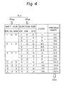
- FIG. 4 is an explanatory drawing of a table memory.
- the table memory can be comprised of a read only memory (ROM) contained in a control unit (corresponding to the control unit 9 of Fig. 1), which will be explained with reference to Fig. 5 hereinafter.
- ROM read only memory
- the gear position signal PS GH and PS GE F ig. 3 are applied, as an input data D in , and corresponding variables regarding the gear position are provided therefrom as an output data D out , through a judgement process.
- this table memory at the left half column side, logics "0" and "1" of the gear position signals Ps GH and PS GE are shown.
- Each logic “1” indicates that the corresponding gear position switch, such as G135, GN --- G5R, is closed, while the logic “0” indicates that it is open.
- Symbol "X” indicates a "don't care” status, i.e., the logic may be “1” or "0” and either will do. The judgement is made in response to each combination of the logics “1” and “0". For example, when the signals PS GH and PS GE assume logics "100" as the shift-side and "010" as the selection-side, it is judged that the third (3) gear position is now selected.
- the first (1) through fifth (5) gear positions, the reverse (R) gear, and three neutral gear (N1, N2, N3) positions can be determined.in accordance with logics "0" and "1" of the signals PS GH and PS GE .
- * 1 denotes a shift-selection illegal state, where each of the signals PS GH and PS GE exhibits "000" logic.
- * 2 denotes a shift-illegal state, * 3 a neutral-selection illegal state, and * 4 a selection illegal state.
- Rows including * 1 through * 4 represent unidentified states-which may be provided during the gear changes from one gear position to another gear position.
- the right side column indicates variables GEAR regarding the gear position.
- the variables GEAR are indicated in the form of machine words and express the conditions set in the transmission gear box (refer to 5 of Fig. 1).
- Each machine word is composed by 1 byte data, i.e., 8 bit data, wherein each lower 4 bits expresses a respective established gear position, i.e., 01, 03, 05 --- 06, while each upper 4 bits expresses auxiliary information.
- Each symbol "+” represents information obtained by ORing with the corresponding lower 4 bit data of the gear position established immediately beforehand. Therefore, such information "+” can be utilized for executing a so-called retry operation.
- the retry operation is well known and is generally available in a manually operated transmission to enable a smooth reset of a gear position even though the preceding gear change did not succeed in setting that same gear position. If, for example, the gear position is set in the shift-illegal state ( * 2) during the retry operation, and if, for example, the gear position established immediately beforehand is expressed as "02", then the variable GEAR should be expressed as "12", i.e., 10 + 02.
- the following table displays a sequence arbitrarily selecting one gear change, i.e., from the second gear position (2) to the third gear position (3).
- the upper row represents-each actual gear position, which corresponds to the value in the column "JUDGE” shown in Fig. 4, and the lower row represents each variable of the gears, which corresponds to the value in the column "VARIABLE” shown in Fig. 4.
- N/V ratio table memory (mentioned hereinafter) in response to the thus-obtained resultant judgement.
- This N/V ratio can be defined as wherein FG denotes a final gear ratio, TG a transmission gear ratio, and r a radius of the drive wheel (7 in Fig. 1).
- the obtained N/V ratio value, the rotation speed a obtained from the rotational input-shaft speed indication signal IS S , and the automobile speed ⁇ obtained from the automobile speed indication signal IS A are used to determine the gear position, in accordance with the following equation which derives a determination factor n.
- the symbol y denotes a predetermined constant for compensation of error.
- the constant y itself is not absolutely essential in the present invention, and may be any value, for example, +500 rpm.
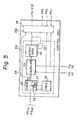
- FIG. 5 is a functional block diagram of a part of a control unit.
- the control unit 39 receives, at least, the-gear position signals PS GH and PS GE (stored in the buffer registers BF 1 and BF 2 of Figs. 3 and 7, but not shown in Fig. 5), the rotation speed a output by the rotational input-shaft speed indication signal IS S , and the automobile speed ⁇ output by the automobile speed - indication signal IS A , and as a result, produces the actuation signal to be applied to the clutch actuator 4' and the transmission actuator 5', by means of the solenoid valve 6.
- the actuation signal is produced from the usual instruction element 36 (refer to Fig. 2), as in the control unit 9 of Fig. 1.
- the diagnostic check element 35 includes therein at least a judging element 31, a table referring element 32 (refer to the table memory of Fig. 4), a calculating element 33, and a determining element 34.
- the judging element.31 produces the aforesaid N/V ratio data and sends it to the calculating element 33 by cooperating with the table referring element 32.
- the calculating element 33 executes the aforesaid arithmetic equation, i.e.,
- the determining element 34 determines whether or not the gear-out operation is completed, and also, whether or not the gear-in operation is completed based on the thus given determination factor n. If the determination obtains a trouble-free response, the actuation signal from the element 36 becomes effective.
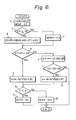
- FIG. 6 is flow chart revealing the diagnostic procedure performed in the diagnostic check element 35 shown in Fig. 5.
- step a the table memory (32) is accessed by the judging element 31, but initially a provisional variable GEAR G3 is arbitrarily specified, in which G3 is a value selected from the right side column of Fig. 4.
- step b if G3 ⁇ OE (expressed in hexadecimal notation) stands, a legal state is assumed, and therefore, in step c, the value G3 is set for the variable GEAR as it is. If G3 ⁇ OE does not stand, an illegal state is assumed, and therefore, in step d, (GEAR AND OF) is added to G3 to obtain a legal variable of the gear position.
- step e an inherent diagnostic check is executed from step e.
- step g if y ⁇ y (y is the previously-mentioned constant for compensation used in the related equation) stands, the gear-in operation is determined under the aforesaid condition (1), in step h, by the determining element 34 . (Fig. 5), while if it does not stand, the gear-out operation is determined under the aforesaid condition (2) in step l.
- step j whether or not G2 is in a range of 01 through 06 is examined. If the result is "No", the check is completed, since it is concluded that the gear position is neutral. If the result of step j is "Yes", a similar equation to that of the step f is executed with respect to the variable G2.
- Figure 7 is a schematic and explanatory diagram representing the diagnostic check element of Fig. 5.
- the variable GEAR from the table 32 is, on one hand, supplied to the usual instruction element 36, and, on the other hand, to the previously mentioned N/V ratio table memory 41, which receives the variable such as 01, 02 ..., and produces a corresponding value of the N/V ratio.
- the N/V ratio value is then given to a multiplier 42 to produce, with the automobile speed ⁇ , the values shown in Fig. 6. as N/V(G) x 6 and N/V(G2) x ⁇ , at steps f and k.
- steps f and k the rotation speed a is subtracted by the thus multiplied value at a subtractor 43, to obtain the values a - N/V(G) x ⁇ and a - N/V(G2) x ⁇ .
- the absolute values thereof can be obtained via an absolute value generating element 44 to produce each value of y to be obtained in these steps f and k.
- the thus generated absolute value y is applied to a comparator 45 having, as a threshold level, the aforesaid constant y for compensation of error, so that steps g, b, and l of Fig. 6 can be performed.
- the gear change operation i.e., gear-out and gear-in
- the next operation for example, engagement of the clutch 4
- the gear change element 35 of Fig. 5 is very important.
- a diagnostic check for the switches of the sensor 21 it is preferable to also perform a diagnostic check for the switches of the sensor 21. It is further preferable that, if a failure occurs in one or more of the switches, a backup should be provided for the abnormal switch or switches. That is, even if such a failure occurs, the aforesaid diagnostic check on whether or not the gear change is completed still can be maintained.
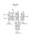
- Figure 8 illustrates a functional block diagram of part of an example of a control unit according the present invention.
- the switch check and backup element 50 of Fig. 8 is incorporated into the diagnostic check element 35 shown in Fig. 5.
- a short-circuited switch recovering element 51 functions to find a short-circuited switch and then effect a mask operation thereto, thereby invalidating the switch.
- a mode . discriminating element 52 follows the short-circuited switch element 51, and discrimates whether or not a running mode or a gear-changing mode is established.
- the term running mode means that the output of the engine 3 (Fig. 1) is engaged with the drive wheel 7 (Fig. 1).
- a running mode determining element 53 functions to finally find the open-circuit switch, caused by a failure, with the aid of a part 55 (mentioned later) in accordance with information received regarding the condition of the clutch and the condition of the transmission gear to be selected.
- 'A gear-changing mode determining element 54 functions to also finally find such an open-circuit switch caused by a failure, with the aid of the element 55 during a gear change operation, in accordance with information received regarding the condition of the clutch, the condition of the transmission gear to be selected, and the rotation speed a.
- the above-mentioned element 55 is a gear-change confirmation element which functions to confirm whether or not the desired transmission gear-in operation is completed, and allows the element 36 to produce the actuation signal. Also, if a switch failure exists, this element functions to confirm whether or not the related gear change is completed, based on a judgement of whether or not the rotation of the input-shaft is normal. The operation of the switch check and backup element 50 will be explained below.
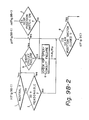
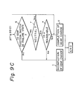
- FIGS 9A, 9B, and 9C are flow charts revealing the diagnostic procedure performed in the switch check and backup element 50 shown in Fig. 8.
- the flow shown in Fig. 9A is of the short-circuited failure of the switch dealt with by the element 51 of Fig. 8.
- two or more switches at the shift-side (Fig. 3) must not be closed simultaneously.
- two or more switches at the selection-side must not be closed simultaneously. If, however, it is determined that a short-circuited failure has occurred, in step a of Fig. 9A, whether or not two or more switches have closed simultaneously is determined. If the result is "Yes”, step b follows, but if "No", step e follows. Step a and the following steps are executed for the shift-side switches and selection-side switches separately and alternately.
- step b i.e., when two or more switches are closed, whether or not each of the closed switches is masked is determined. If the result is "Yes” (this means that the switch was in a failure state), step c follows, but if "No” (this means that the switch was normal), step d follows.
- the term “mask” is defined as a particular bit (logic “1”) for indicating that the on/off information of the corresponding switch is now invalid. The mask bit is variable, and therefore, if the failed switch is restored, the mask bit is reset to logic "0".
- step c the switch having the mask bit of logic "1", i.e., a masked switch signal, is disregarded and treated as an open switch, i.e., the switch was in a failure state and is still in a failure state.
- step e the mask bit is newly given to the switches now in a failure state.
- step e the mask signal is cancelled for the open switch or open switches.
- an alarm signal ALM S is provided from the element 51 and given to the indicator 10 of Fig. 1. This ALMs signal indicates that a permanent short-circuit failure has occurred in the switch, while the corresponding switch signal indicating "closed” is further treated as invalid.
- Figure 10 is a circuit diagram of an example of a mask treating circuit.
- the mask treating circuit 60 receives an inherent gear position signal PSGH , as an input data, and then produces a mask processed signal MPS GH as an output data.
- the signal MPS GH is then supplied to the mode discriminating element 52 of Fig. 8.
- an identical circuit to the circuiav 50 also exists for working with respect to the other signal PS GE and for producing the other mask pr ocessed signal MPS GH .
- the function of the circuit 60 can also be achieved by predetermined programs as a software process.
- the circuit 60 is comprised of a plurality of ANDgates62, inverters 64; and flip ⁇ flops (FF)66, and an OR gate 68 and NOR gate 70,as illustrated.
- the output A from the ORgate 68 indicates when logic "I", that two or more switches are closed simultaneously.
- the output B from the NORgate 70 indicates when logic "1", that no masked switch signals exist.
- the inputs of this NOR gate 70 represent mask command signals C. When the signal or signals C are logic "1”, the corresponding switch signal or signals are masked. Once the corresponding switch signal is changed to logic "0" (i.e., the short circuit failure is restored), the corresponding F F '66 is reset.
- step f if the mode discriminating element 52 (Fig. 8) determines that the running mode is now held, step l follows, while if it determines that the gear changing mode is now held, step g follows.
- step g i.e., when the gear change operation is executed, element 54 (Fig. 8) determines whether or not the clutch 4 (Fig. 1) is normal. If ("Yes"), step h follows, while if "No", step p follows.
- step h the element 54 determines whether or not the gear position switch selected immediately before is changed from a closed state to an open state.
- step i the element 54 determines whether or not the desired gear position is neutral or not. If the result is "Yes”, step k follows, while if "No”, step j follows. In step j, the element 54 determines whether or not the rotation speed a of the input-shaft is reasonable in view of the N/V ratio value and the automobile speed ⁇ . If the result is "Yes”, step k follows, while if "No”, step p follows.
- step k the element 35 determines whether or not there exists a short-circuit failure at the gearposition switch to be selected. If the result is "Yes”, step p follows, while if "No", step o follows. If the result of step k is "No”, i.e., when no short-circuit failure exists, then a diagnostic check for the switch is achieved by the element 55, from the standpoint of whether or not an open switch failure exists.
- step 1 whether or not the clutch 4 (Fig. 1) is completely engaged is determined. If the result is “Yes”, step m follows, while if "No”, step p follows. In step m, it is determined whether or not the desired gear position is neutral. If the result is “Yes”, step p follows, while if "No”, step n follows. In step n, it is determined whether or not the desired gear position switch is ON. If the result is “Yes”, step p follows, while if "No”, the diagnostic check for the switch regarding an open-switch failure is started.
- an alarm signal ALM O indicating a permanent open-circuit failure is generated and given to the indicator 10 (Fig. 1), while the element 55 (Fig. 8) further carries out its operation regardless of the existence or nonexistence of these failure signals ALMs and ALM O .
- the open-switch failure for the switch can be performed by detecting if the switch concerned is "OPEN" when it should be closed.
- Steps p through u are dealt with chiefly by the gear change confirmation element 55 of Fig. 8.
- step p it is determined whether or not the desired gear position switch is closed. If the result is "Yes”, it ... is confirmed, in step u, that the related gear change operation is completed. This allows the element 36: (Fig. 5) to produce the relevant activation signal. If the result of step p is "No”, it is determined, in step q, whether or not the desired gear position switch is in a failure state. If the result-is "Yes”, step r follows, while if "No", it is determined that the concerned gear change operation is not yet completed, and therefore, the element 55 inhibits the elemenv 36 from producing the activation signal.
- step r it is determined whether or not the desired gear position is neutral. If the result is “Yes”, step u follows, while if "No", step s follows. In step s, it is determined whether or not the rotation speed a of the input-shaft is reasonable, taking into account the N/V ratio value and the automobile speed ⁇ . If the result is "Yes”, step u follows, while if "No", step t follows.
- the diagnostic processing system can determine the completion of the gear change operation by utilizing the gear position sensor, and can also check the normality of the gear position sensor. Furthermore, even if a failure of the sensor occurs, the system can still oversee the completion of the gear change with a high accuracy, to some extent.
Landscapes
- Engineering & Computer Science (AREA)
- Mechanical Engineering (AREA)
- General Engineering & Computer Science (AREA)
- Transportation (AREA)
- Automation & Control Theory (AREA)
- Chemical & Material Sciences (AREA)
- Combustion & Propulsion (AREA)
- Human Computer Interaction (AREA)
- Control Of Transmission Device (AREA)
Applications Claiming Priority (4)
| Application Number | Priority Date | Filing Date | Title |
|---|---|---|---|
| JP119170/83 | 1983-06-30 | ||
| JP119161/83 | 1983-06-30 | ||
| JP58119161A JPS6011765A (ja) | 1983-06-30 | 1983-06-30 | 変速段の検出方式 |
| JP58119170A JPS6011767A (ja) | 1983-06-30 | 1983-06-30 | 変速装置 |
Publications (2)
| Publication Number | Publication Date |
|---|---|
| EP0134646A1 true EP0134646A1 (de) | 1985-03-20 |
| EP0134646B1 EP0134646B1 (de) | 1988-10-26 |
Family
ID=26456946
Family Applications (1)
| Application Number | Title | Priority Date | Filing Date |
|---|---|---|---|
| EP84304496A Expired EP0134646B1 (de) | 1983-06-30 | 1984-06-29 | Steuersystem für automatische Fahrzeuggetriebe |
Country Status (8)
| Country | Link |
|---|---|
| US (1) | US4642771A (de) |
| EP (1) | EP0134646B1 (de) |
| JP (1) | JPS6011765A (de) |
| KR (1) | KR880000074B1 (de) |
| AU (1) | AU544230B2 (de) |
| CA (1) | CA1223069A (de) |
| DE (1) | DE3474849D1 (de) |
| ES (1) | ES8601418A1 (de) |
Cited By (11)
| Publication number | Priority date | Publication date | Assignee | Title |
|---|---|---|---|---|
| EP0217540A1 (de) * | 1985-08-29 | 1987-04-08 | Isuzu Motors Limited | Verfahren und Vorrichtung zum Steuern des Schaltvorganges bei automatischen Fahrzeuggetrieben |
| US4790204A (en) * | 1987-07-16 | 1988-12-13 | Automotive Products, Plc | Electric shift apparatus |
| US4817471A (en) * | 1987-07-16 | 1989-04-04 | Tury Edward L | Electrical control system for control of an automatic transmission apparatus |
| EP0296775A3 (en) * | 1987-06-20 | 1989-10-18 | Isuzu Motors Limited | Electronic control system for automatic vehicle transmission |
| EP0242086B1 (de) * | 1986-04-18 | 1990-06-13 | Eaton Corporation | Verfahren zum Steuern eines automatischen mechanischen Getriebes einschliesslich Fehlererkennung und zulässiger Abweichung betreffend das Signal eines Messfühlers für die Leeraufstellung des Getriebes |
| US4998444A (en) * | 1987-07-16 | 1991-03-12 | Automotive Products (Usa) Inc. | Control system for electric shift apparatus |
| US5014038A (en) * | 1987-09-14 | 1991-05-07 | Automotive Products (Usa) Inc. | Motor vehicle control system |
| EP0403273A3 (de) * | 1989-06-15 | 1991-06-26 | Diesel Kiki Co. Ltd. | System zum automatischen Steuern von Fahrzeuggetrieben |
| US5035158A (en) * | 1989-09-25 | 1991-07-30 | Automotive Products (Usa) Inc. | Electric shift and transfer case apparatus with control system therefore |
| US5042133A (en) * | 1989-03-15 | 1991-08-27 | Automotive Products (Usa) Inc. | Testing method for electric shift control apparatus |
| EP0602849A1 (de) * | 1992-12-18 | 1994-06-22 | Eaton Corporation | Verfahren zur Fehlerbeseitigung bei erfolglosen Schaltversuchen aus dem Leerlauf in automatischen oder halbautomatischen mechanischen Getriebesystemen |
Families Citing this family (13)
| Publication number | Priority date | Publication date | Assignee | Title |
|---|---|---|---|---|
| US4969099A (en) * | 1986-03-11 | 1990-11-06 | Toyota Jidosha Kabushiki Kaisha | Double-detecting, trouble-judging and failsafe devices in system for integrally controlling automatic transmission and engine |
| EP0545900A3 (en) * | 1987-02-04 | 1997-08-06 | Komatsu Mfg Co Ltd | Method of automatically changing speed of dump truck for use as constrcution vehicle |
| US5113720A (en) * | 1987-06-24 | 1992-05-19 | Kabushiki Kaisha Komatsu Seisakusho | Apparatus for controlling gear box |
| JPH07117151B2 (ja) * | 1988-04-20 | 1995-12-18 | 日産自動車株式会社 | 自動変速機の変速制御装置 |
| US4981822A (en) * | 1989-02-17 | 1991-01-01 | General Electric Company | Composite containing coated fibrous material |
| US6026784A (en) | 1998-03-30 | 2000-02-22 | Detroit Diesel Corporation | Method and system for engine control to provide driver reward of increased allowable speed |
| GB9412805D0 (en) * | 1994-06-25 | 1994-08-17 | Eaton Corp | Engagement fault degraded mode control |
| JPH1018900A (ja) * | 1996-07-03 | 1998-01-20 | Nissan Motor Co Ltd | 検出手段の診断装置およびエンジンの失火診断装置 |
| US6056669A (en) * | 1996-10-04 | 2000-05-02 | Ford Global Technologies, Inc. | Shift controls for automated shifting manual transmissions with range sensing redundancy |
| US6492900B2 (en) | 1999-06-25 | 2002-12-10 | Honda Of America Manufacturing, Inc. | Rotary switch test sensor |
| FR2861155B1 (fr) * | 2003-10-17 | 2005-12-16 | Siemens Vdo Automotive | Procede de determination du rapport engage dans une boite de vitesses |
| US8086380B2 (en) * | 2006-11-17 | 2011-12-27 | GM Global Technology Operations LLC | Variable bleed solenoid recovery system |
| FR3028586B1 (fr) * | 2014-11-17 | 2016-12-23 | Peugeot Citroen Automobiles Sa | Procede et dispositif d’apprentissage des positions de rapports dans une boite de vitesses de vehicule, par comparaison de valeurs |
Citations (9)
| Publication number | Priority date | Publication date | Assignee | Title |
|---|---|---|---|---|
| US3530668A (en) * | 1968-03-30 | 1970-09-29 | Gunter Siebers | Rapid gear-change apparatus |
| DE2338122A1 (de) * | 1973-07-27 | 1975-02-13 | Daimler Benz Ag | Vorrichtung zum selbsttaetigen schalten von stufenwechselgetrieben |
| DE2341797A1 (de) * | 1973-08-17 | 1975-02-27 | Nissan Motor | Steuervorrichtung fuer eine getriebekupplung |
| US3937105A (en) * | 1973-08-29 | 1976-02-10 | Toyoto Jidosha Kogyo Kabushiki Kaisha | Automatic transmission system for use with automobiles |
| US3946842A (en) * | 1969-06-13 | 1976-03-30 | Gunter Siebers | Electric and fluid controls for clutch and transmission |
| DE1809021B2 (de) * | 1968-11-15 | 1977-07-28 | Zahnräderfabrik Renk AG, 8900 Augsburg | Sicherheitsschaltvorrichtung zur verhinderung schaeden verursachender fehlschaltungen bei elektrisch gesteuerten fahrzeuggetrieben |
| DE1505535B2 (de) * | 1966-01-27 | 1977-09-01 | Selbsttätige elektrische Steuereinrichtung für ein Kraftfahrzeug-Zahnräderwechselgetriebe Robert Bosch GmbH, 7000 Stuttgart | Selbsttaetige elektrische steuereinrichtung fuer ein kraftfahrzeug-zahnraederwechselgetriebe |
| EP0046845A2 (de) * | 1980-08-28 | 1982-03-10 | WABCO Westinghouse Fahrzeugbremsen GmbH | Halbautomatische Getriebesteuerung |
| FR2511107A1 (fr) * | 1981-08-07 | 1983-02-11 | Cef Centre Etd Fraisage | Dispositif de commande de changement de vitesse de boite a engrenages |
Family Cites Families (10)
| Publication number | Priority date | Publication date | Assignee | Title |
|---|---|---|---|---|
| DE2036732C3 (de) * | 1970-07-24 | 1979-05-23 | Robert Bosch Gmbh, 7000 Stuttgart | Anordnung zum synchronisierten Schalten von Stufenwechselgetrieben in Fahrzeugen |
| IT939884B (it) * | 1971-09-25 | 1973-02-10 | Fiat Spa | Cambio a sincronizzazione elettroni ca particolarmente per autoveicoli |
| DE2700548A1 (de) * | 1977-01-07 | 1978-07-13 | Bosch Gmbh Robert | Sicherheitsschaltung fuer elektronische getriebesteuerungen |
| JPS5531669A (en) * | 1978-08-30 | 1980-03-06 | Toyota Motor Corp | Speed change timing instructor for vehicle speed change gear |
| JPS5576244A (en) * | 1978-12-04 | 1980-06-09 | Toyota Motor Corp | Selective control method of auxiliary change gear for automobile use |
| JPS55132452A (en) * | 1979-04-03 | 1980-10-15 | Nissan Motor Co Ltd | Speed change control device for automatic speed changer |
| SE420296B (sv) * | 1980-11-28 | 1981-09-28 | Saab Scania Ab | Forfarande for att forhindra felaktigt vexelval vid en fordonstransmission |
| JPS57204360A (en) * | 1981-06-05 | 1982-12-15 | Nippon Denso Co Ltd | Electronic automatic speed change gear |
| JPS5817246A (ja) * | 1981-07-23 | 1983-02-01 | Nippon Denso Co Ltd | 自動変速制御装置 |
| JPS58177728A (ja) * | 1982-04-13 | 1983-10-18 | Toyota Motor Corp | 車両の最適シフト位置表示装置 |
-
1983
- 1983-06-30 JP JP58119161A patent/JPS6011765A/ja active Pending
-
1984
- 1984-06-20 CA CA000456999A patent/CA1223069A/en not_active Expired
- 1984-06-26 AU AU29891/84A patent/AU544230B2/en not_active Ceased
- 1984-06-28 US US06/625,681 patent/US4642771A/en not_active Expired - Fee Related
- 1984-06-29 DE DE8484304496T patent/DE3474849D1/de not_active Expired
- 1984-06-29 KR KR1019840003723A patent/KR880000074B1/ko not_active Expired
- 1984-06-29 EP EP84304496A patent/EP0134646B1/de not_active Expired
- 1984-06-29 ES ES533840A patent/ES8601418A1/es not_active Expired
Patent Citations (9)
| Publication number | Priority date | Publication date | Assignee | Title |
|---|---|---|---|---|
| DE1505535B2 (de) * | 1966-01-27 | 1977-09-01 | Selbsttätige elektrische Steuereinrichtung für ein Kraftfahrzeug-Zahnräderwechselgetriebe Robert Bosch GmbH, 7000 Stuttgart | Selbsttaetige elektrische steuereinrichtung fuer ein kraftfahrzeug-zahnraederwechselgetriebe |
| US3530668A (en) * | 1968-03-30 | 1970-09-29 | Gunter Siebers | Rapid gear-change apparatus |
| DE1809021B2 (de) * | 1968-11-15 | 1977-07-28 | Zahnräderfabrik Renk AG, 8900 Augsburg | Sicherheitsschaltvorrichtung zur verhinderung schaeden verursachender fehlschaltungen bei elektrisch gesteuerten fahrzeuggetrieben |
| US3946842A (en) * | 1969-06-13 | 1976-03-30 | Gunter Siebers | Electric and fluid controls for clutch and transmission |
| DE2338122A1 (de) * | 1973-07-27 | 1975-02-13 | Daimler Benz Ag | Vorrichtung zum selbsttaetigen schalten von stufenwechselgetrieben |
| DE2341797A1 (de) * | 1973-08-17 | 1975-02-27 | Nissan Motor | Steuervorrichtung fuer eine getriebekupplung |
| US3937105A (en) * | 1973-08-29 | 1976-02-10 | Toyoto Jidosha Kogyo Kabushiki Kaisha | Automatic transmission system for use with automobiles |
| EP0046845A2 (de) * | 1980-08-28 | 1982-03-10 | WABCO Westinghouse Fahrzeugbremsen GmbH | Halbautomatische Getriebesteuerung |
| FR2511107A1 (fr) * | 1981-08-07 | 1983-02-11 | Cef Centre Etd Fraisage | Dispositif de commande de changement de vitesse de boite a engrenages |
Cited By (13)
| Publication number | Priority date | Publication date | Assignee | Title |
|---|---|---|---|---|
| US4766774A (en) * | 1985-08-29 | 1988-08-30 | Isuzu Motors Limited | Shift control method and apparatus for automatic transmissions used in automotive vehicles |
| EP0217540A1 (de) * | 1985-08-29 | 1987-04-08 | Isuzu Motors Limited | Verfahren und Vorrichtung zum Steuern des Schaltvorganges bei automatischen Fahrzeuggetrieben |
| EP0242086B1 (de) * | 1986-04-18 | 1990-06-13 | Eaton Corporation | Verfahren zum Steuern eines automatischen mechanischen Getriebes einschliesslich Fehlererkennung und zulässiger Abweichung betreffend das Signal eines Messfühlers für die Leeraufstellung des Getriebes |
| EP0296775A3 (en) * | 1987-06-20 | 1989-10-18 | Isuzu Motors Limited | Electronic control system for automatic vehicle transmission |
| US4998444A (en) * | 1987-07-16 | 1991-03-12 | Automotive Products (Usa) Inc. | Control system for electric shift apparatus |
| US4817471A (en) * | 1987-07-16 | 1989-04-04 | Tury Edward L | Electrical control system for control of an automatic transmission apparatus |
| US4790204A (en) * | 1987-07-16 | 1988-12-13 | Automotive Products, Plc | Electric shift apparatus |
| USRE34064E (en) * | 1987-07-16 | 1992-09-15 | Automotive Products (Usa) Inc. | Electric shift apparatus |
| US5014038A (en) * | 1987-09-14 | 1991-05-07 | Automotive Products (Usa) Inc. | Motor vehicle control system |
| US5042133A (en) * | 1989-03-15 | 1991-08-27 | Automotive Products (Usa) Inc. | Testing method for electric shift control apparatus |
| EP0403273A3 (de) * | 1989-06-15 | 1991-06-26 | Diesel Kiki Co. Ltd. | System zum automatischen Steuern von Fahrzeuggetrieben |
| US5035158A (en) * | 1989-09-25 | 1991-07-30 | Automotive Products (Usa) Inc. | Electric shift and transfer case apparatus with control system therefore |
| EP0602849A1 (de) * | 1992-12-18 | 1994-06-22 | Eaton Corporation | Verfahren zur Fehlerbeseitigung bei erfolglosen Schaltversuchen aus dem Leerlauf in automatischen oder halbautomatischen mechanischen Getriebesystemen |
Also Published As
| Publication number | Publication date |
|---|---|
| ES533840A0 (es) | 1985-10-16 |
| AU2989184A (en) | 1985-02-28 |
| DE3474849D1 (en) | 1988-12-01 |
| KR880000074B1 (ko) | 1988-02-22 |
| AU544230B2 (en) | 1985-05-23 |
| EP0134646B1 (de) | 1988-10-26 |
| ES8601418A1 (es) | 1985-10-16 |
| CA1223069A (en) | 1987-06-16 |
| US4642771A (en) | 1987-02-10 |
| JPS6011765A (ja) | 1985-01-22 |
| KR850000320A (ko) | 1985-02-26 |
Similar Documents
| Publication | Publication Date | Title |
|---|---|---|
| EP0134646B1 (de) | Steuersystem für automatische Fahrzeuggetriebe | |
| JP2584765B2 (ja) | 自動変速機の変速制御装置 | |
| US4523281A (en) | Automatic transmission controller for automobiles | |
| US4955258A (en) | Device and method of fail-safe control for electronically controlled automatic transmission | |
| US5396420A (en) | Control unit for automatic transmissions in motor vehicles | |
| CN1307379C (zh) | 用于自动传动的输入轴速度传感器的故障诊断方法 | |
| CA2108947C (en) | Fault tolerant method of transmission gear selection | |
| US4685051A (en) | Revolution signal processing system for vehicular electronic controller | |
| JPH0619666B2 (ja) | 故障診断処理方式 | |
| JPH0416667B2 (de) | ||
| US6067492A (en) | Display system for automatic transmissions | |
| US5598334A (en) | System for determining an abnormal operating condition in speed ratios of an automatic transmission and a method therefor | |
| EP0065528A1 (de) | Verfahren zur selbsttätigen auswahl eines ganges in einer kraftübertragung | |
| EP0479464B1 (de) | Steuerung eines Getriebes unter Berücksichtigung der Viskosität des Getriebeöls | |
| EP0922604B1 (de) | Steuerung eines Getriebes mit elektrischer Schaltbetätigung, insbesondere mit Bestimmung der Kupplungsstellung | |
| US4789937A (en) | Method and system for shift control of an automatic transmission | |
| KR960008278A (ko) | 차량의 총중량을 나타내는 제어파라미터의 값을 디폴트값에 재설정하는 방법 및 장치 | |
| CA2198550A1 (en) | Electronic controller for identifying and operating an automated manual transmission | |
| JPS6034562A (ja) | 自動変速機変速制御方式 | |
| US5669848A (en) | Control system for automatic transmission for vehicle | |
| EP0781942B1 (de) | Steuerung für ein Automatikgetriebe und Methode zur Gangrückschaltung | |
| JP2000097337A (ja) | 自動変速機の表示装置 | |
| JPH1018896A (ja) | 車速検出装置の故障診断装置 | |
| JPS58159114A (ja) | 車両の自動定速走行装置の制御装置 | |
| EP0454041A1 (de) | Getriebesteuerungssystem |
Legal Events
| Date | Code | Title | Description |
|---|---|---|---|
| PUAI | Public reference made under article 153(3) epc to a published international application that has entered the european phase |
Free format text: ORIGINAL CODE: 0009012 |
|
| AK | Designated contracting states |
Designated state(s): CH DE FR GB IT LI SE |
|
| 17P | Request for examination filed |
Effective date: 19850827 |
|
| 17Q | First examination report despatched |
Effective date: 19860502 |
|
| GRAA | (expected) grant |
Free format text: ORIGINAL CODE: 0009210 |
|
| AK | Designated contracting states |
Kind code of ref document: B1 Designated state(s): CH DE FR GB IT LI SE |
|
| REF | Corresponds to: |
Ref document number: 3474849 Country of ref document: DE Date of ref document: 19881201 |
|
| ET | Fr: translation filed | ||
| ITF | It: translation for a ep patent filed | ||
| PLBE | No opposition filed within time limit |
Free format text: ORIGINAL CODE: 0009261 |
|
| STAA | Information on the status of an ep patent application or granted ep patent |
Free format text: STATUS: NO OPPOSITION FILED WITHIN TIME LIMIT |
|
| 26N | No opposition filed | ||
| ITTA | It: last paid annual fee | ||
| EAL | Se: european patent in force in sweden |
Ref document number: 84304496.7 |
|
| PGFP | Annual fee paid to national office [announced via postgrant information from national office to epo] |
Ref country code: FR Payment date: 19950609 Year of fee payment: 12 |
|
| PGFP | Annual fee paid to national office [announced via postgrant information from national office to epo] |
Ref country code: SE Payment date: 19950615 Year of fee payment: 12 |
|
| PGFP | Annual fee paid to national office [announced via postgrant information from national office to epo] |
Ref country code: DE Payment date: 19950617 Year of fee payment: 12 |
|
| PGFP | Annual fee paid to national office [announced via postgrant information from national office to epo] |
Ref country code: GB Payment date: 19950619 Year of fee payment: 12 |
|
| PGFP | Annual fee paid to national office [announced via postgrant information from national office to epo] |
Ref country code: CH Payment date: 19950623 Year of fee payment: 12 |
|
| PG25 | Lapsed in a contracting state [announced via postgrant information from national office to epo] |
Ref country code: GB Effective date: 19960629 |
|
| PG25 | Lapsed in a contracting state [announced via postgrant information from national office to epo] |
Ref country code: LI Effective date: 19960630 Ref country code: CH Effective date: 19960630 Ref country code: SE Effective date: 19960630 |
|
| REG | Reference to a national code |
Ref country code: CH Ref legal event code: PL |
|
| GBPC | Gb: european patent ceased through non-payment of renewal fee |
Effective date: 19960629 |
|
| PG25 | Lapsed in a contracting state [announced via postgrant information from national office to epo] |
Ref country code: FR Effective date: 19970228 |
|
| PG25 | Lapsed in a contracting state [announced via postgrant information from national office to epo] |
Ref country code: DE Effective date: 19970301 |
|
| EUG | Se: european patent has lapsed |
Ref document number: 84304496.7 |
|
| REG | Reference to a national code |
Ref country code: FR Ref legal event code: ST |