EP0134724A1 - Corps de boîte soudé et procédé pour sa fabrication - Google Patents
Corps de boîte soudé et procédé pour sa fabrication Download PDFInfo
- Publication number
- EP0134724A1 EP0134724A1 EP84306097A EP84306097A EP0134724A1 EP 0134724 A1 EP0134724 A1 EP 0134724A1 EP 84306097 A EP84306097 A EP 84306097A EP 84306097 A EP84306097 A EP 84306097A EP 0134724 A1 EP0134724 A1 EP 0134724A1
- Authority
- EP
- European Patent Office
- Prior art keywords
- welded
- steel sheet
- weld
- welding
- mash seam
- Prior art date
- Legal status (The legal status is an assumption and is not a legal conclusion. Google has not performed a legal analysis and makes no representation as to the accuracy of the status listed.)
- Withdrawn
Links
- 238000004519 manufacturing process Methods 0.000 title claims abstract description 10
- 238000003466 welding Methods 0.000 claims abstract description 68
- 229910000831 Steel Inorganic materials 0.000 claims abstract description 38
- 239000010959 steel Substances 0.000 claims abstract description 38
- 230000014509 gene expression Effects 0.000 claims abstract description 11
- 238000009751 slip forming Methods 0.000 claims abstract description 3
- 239000005028 tinplate Substances 0.000 claims description 9
- 239000005029 tin-free steel Substances 0.000 claims description 8
- 239000010410 layer Substances 0.000 description 13
- 230000007797 corrosion Effects 0.000 description 11
- 238000005260 corrosion Methods 0.000 description 11
- 230000000052 comparative effect Effects 0.000 description 10
- VYZAMTAEIAYCRO-UHFFFAOYSA-N Chromium Chemical compound [Cr] VYZAMTAEIAYCRO-UHFFFAOYSA-N 0.000 description 9
- ATJFFYVFTNAWJD-UHFFFAOYSA-N Tin Chemical compound [Sn] ATJFFYVFTNAWJD-UHFFFAOYSA-N 0.000 description 9
- XEEYBQQBJWHFJM-UHFFFAOYSA-N Iron Chemical group [Fe] XEEYBQQBJWHFJM-UHFFFAOYSA-N 0.000 description 7
- PXHVJJICTQNCMI-UHFFFAOYSA-N Nickel Chemical compound [Ni] PXHVJJICTQNCMI-UHFFFAOYSA-N 0.000 description 6
- QDOXWKRWXJOMAK-UHFFFAOYSA-N dichromium trioxide Chemical compound O=[Cr]O[Cr]=O QDOXWKRWXJOMAK-UHFFFAOYSA-N 0.000 description 6
- 239000002344 surface layer Substances 0.000 description 6
- 229910001209 Low-carbon steel Inorganic materials 0.000 description 5
- 230000001476 alcoholic effect Effects 0.000 description 5
- 230000007547 defect Effects 0.000 description 5
- 239000004922 lacquer Substances 0.000 description 5
- OXNIZHLAWKMVMX-UHFFFAOYSA-N picric acid Chemical compound OC1=C([N+]([O-])=O)C=C([N+]([O-])=O)C=C1[N+]([O-])=O OXNIZHLAWKMVMX-UHFFFAOYSA-N 0.000 description 5
- 239000002244 precipitate Substances 0.000 description 5
- UQSXHKLRYXJYBZ-UHFFFAOYSA-N Iron oxide Chemical compound [Fe]=O UQSXHKLRYXJYBZ-UHFFFAOYSA-N 0.000 description 4
- 239000011248 coating agent Substances 0.000 description 4
- 238000000576 coating method Methods 0.000 description 4
- 238000002844 melting Methods 0.000 description 4
- 230000008018 melting Effects 0.000 description 4
- 239000007790 solid phase Substances 0.000 description 4
- RYGMFSIKBFXOCR-UHFFFAOYSA-N Copper Chemical compound [Cu] RYGMFSIKBFXOCR-UHFFFAOYSA-N 0.000 description 3
- 239000004593 Epoxy Substances 0.000 description 3
- 208000037048 Prodromal Symptoms Diseases 0.000 description 3
- 238000010586 diagram Methods 0.000 description 3
- 239000007788 liquid Substances 0.000 description 3
- 229910052751 metal Inorganic materials 0.000 description 3
- 239000002184 metal Substances 0.000 description 3
- 238000000034 method Methods 0.000 description 3
- 229910052759 nickel Inorganic materials 0.000 description 3
- ISWSIDIOOBJBQZ-UHFFFAOYSA-N phenol group Chemical group C1(=CC=CC=C1)O ISWSIDIOOBJBQZ-UHFFFAOYSA-N 0.000 description 3
- XLYOFNOQVPJJNP-UHFFFAOYSA-N water Substances O XLYOFNOQVPJJNP-UHFFFAOYSA-N 0.000 description 3
- WGLPBDUCMAPZCE-UHFFFAOYSA-N Trioxochromium Chemical compound O=[Cr](=O)=O WGLPBDUCMAPZCE-UHFFFAOYSA-N 0.000 description 2
- 230000015572 biosynthetic process Effects 0.000 description 2
- 229910000423 chromium oxide Inorganic materials 0.000 description 2
- 238000001816 cooling Methods 0.000 description 2
- 229910052802 copper Inorganic materials 0.000 description 2
- 239000010949 copper Substances 0.000 description 2
- 230000007423 decrease Effects 0.000 description 2
- 210000001787 dendrite Anatomy 0.000 description 2
- 238000005530 etching Methods 0.000 description 2
- 238000001125 extrusion Methods 0.000 description 2
- 108010053481 Antifreeze Proteins Proteins 0.000 description 1
- 229910000640 Fe alloy Inorganic materials 0.000 description 1
- 229910001030 Iron–nickel alloy Inorganic materials 0.000 description 1
- 235000007688 Lycopersicon esculentum Nutrition 0.000 description 1
- 240000003768 Solanum lycopersicum Species 0.000 description 1
- 238000003854 Surface Print Methods 0.000 description 1
- 239000011324 bead Substances 0.000 description 1
- KRVSOGSZCMJSLX-UHFFFAOYSA-L chromic acid Substances O[Cr](O)(=O)=O KRVSOGSZCMJSLX-UHFFFAOYSA-L 0.000 description 1
- 229910052804 chromium Inorganic materials 0.000 description 1
- 239000011651 chromium Substances 0.000 description 1
- 238000009792 diffusion process Methods 0.000 description 1
- -1 e.g. Substances 0.000 description 1
- 230000000694 effects Effects 0.000 description 1
- 230000008030 elimination Effects 0.000 description 1
- 238000003379 elimination reaction Methods 0.000 description 1
- AWJWCTOOIBYHON-UHFFFAOYSA-N furo[3,4-b]pyrazine-5,7-dione Chemical compound C1=CN=C2C(=O)OC(=O)C2=N1 AWJWCTOOIBYHON-UHFFFAOYSA-N 0.000 description 1
- 229910052742 iron Inorganic materials 0.000 description 1
- NNIPDXPTJYIMKW-UHFFFAOYSA-N iron tin Chemical class [Fe].[Sn] NNIPDXPTJYIMKW-UHFFFAOYSA-N 0.000 description 1
- 238000003754 machining Methods 0.000 description 1
- 239000000463 material Substances 0.000 description 1
- 230000001151 other effect Effects 0.000 description 1
- 239000012071 phase Substances 0.000 description 1
- 238000003860 storage Methods 0.000 description 1
- 238000011144 upstream manufacturing Methods 0.000 description 1
- 229910000859 α-Fe Inorganic materials 0.000 description 1
Images


Classifications
-
- B—PERFORMING OPERATIONS; TRANSPORTING
- B23—MACHINE TOOLS; METAL-WORKING NOT OTHERWISE PROVIDED FOR
- B23K—SOLDERING OR UNSOLDERING; WELDING; CLADDING OR PLATING BY SOLDERING OR WELDING; CUTTING BY APPLYING HEAT LOCALLY, e.g. FLAME CUTTING; WORKING BY LASER BEAM
- B23K11/00—Resistance welding; Severing by resistance heating
- B23K11/30—Features relating to electrodes
- B23K11/309—Wire electrodes
-
- B—PERFORMING OPERATIONS; TRANSPORTING
- B23—MACHINE TOOLS; METAL-WORKING NOT OTHERWISE PROVIDED FOR
- B23K—SOLDERING OR UNSOLDERING; WELDING; CLADDING OR PLATING BY SOLDERING OR WELDING; CUTTING BY APPLYING HEAT LOCALLY, e.g. FLAME CUTTING; WORKING BY LASER BEAM
- B23K11/00—Resistance welding; Severing by resistance heating
- B23K11/16—Resistance welding; Severing by resistance heating taking account of the properties of the material to be welded
-
- B—PERFORMING OPERATIONS; TRANSPORTING
- B23—MACHINE TOOLS; METAL-WORKING NOT OTHERWISE PROVIDED FOR
- B23K—SOLDERING OR UNSOLDERING; WELDING; CLADDING OR PLATING BY SOLDERING OR WELDING; CUTTING BY APPLYING HEAT LOCALLY, e.g. FLAME CUTTING; WORKING BY LASER BEAM
- B23K11/00—Resistance welding; Severing by resistance heating
- B23K11/06—Resistance welding; Severing by resistance heating using roller electrodes
- B23K11/061—Resistance welding; Severing by resistance heating using roller electrodes for welding rectilinear seams
- B23K11/062—Resistance welding; Severing by resistance heating using roller electrodes for welding rectilinear seams for welding longitudinal seams of tubes
- B23K11/063—Lap welding
Definitions
- This invention relates to a welded can body and the method of making same, more particularly to a welded can body made of a steel sheet or a surface treated steel sheet with its side jointed through a mash seam weld and the method of making the welded can body.
- a welded can body formed of a sheet whose basis is a low carbon steel sheet has often been so made that the opposite margins of a rectangular blank have overlapped each other to form a side lapped portion, and the lapped portion has been mash seam welded with a sinusoidal current using a pair of roller electrodes with relatively small diameters held in a given position directly or through wire electrodes.
- the blank has a surface layer containing an electrically insulating chrome oxide layer such as in case of tinfree steel (electrolytically chromic acid treated steel sheet), to prevent the occurrence of such defects as a splash of a melted metal or the like, normally the mash seam weld has been performed after said surface layer was removed by machining or the like from the margins of the blank.
- an electrically insulating chrome oxide layer such as in case of tinfree steel (electrolytically chromic acid treated steel sheet)
- the heat affected zones have been exposed to the surfaces of the welds. Since these heat affected zones have had nonuniform structure containing fine precipitates of carbide (including the one in a prodromal stage) and therefore have been chemically unstable, these zones have been liable to cause corrosion due to the contents in the sealed cans. Therefore, even when the surfaces of the welds have been repaired with organic films, the exposed portions of the heat affected zones tend to be selectively corroded, resulting in defects such as rusting or pinhole corrosion in the welds.
- the present invention attempts to provide a welded can body having a mash seam weld of a specific type wherein the foregoing problems have been solved.
- defects called pittings in the specification tend to be produced in the weld of the above type, as described below.
- the pitting tends to cause rusting or pinhole in the weld during storage, and induce rupture in such a working as beading or the like.
- the heat affected zone is defined as a region where some change occurred in the structure thereof due to thermal hysteresis during welding, presumably by being heated to a temperature of about 1000°C or above.
- the boundary surfaces of the lapped portion corresponding to the heat affected zone are united with solid phase weld and/or melt weld to form a firm junction.
- a black area 3a, and a gray and/or white area 3b surrounded by the black area 3a are observed in microscopic photographs (refer to Figs. 1 and 2) of about 50 times magnification.
- These areas 3a, and 3b constitute the heat affected zone 2 described herein.
- the black area 3a is supposed to mainly comprise fine precipitates of carbide (including the one in a prodromal stage), and the white area 3b mainly comprise dendrite structure formed by rapid cooling after melting during welding.
- a welded can body made of a steel sheet or a surface treated steel sheet, and jointed with a mash seam weld, characterized in that said mash seam weld comprises a heat affected zone continuously formed over the length thereof, and said heat affected zone is apart from at least the inner surface of said mash seam weld.
- a welded can body with a mash seam weld which is made of a steel sheet or a surface treated steel sheet the effect that the weld is not caused to peel off or rupture by working such as beading, necking or flanging, and thus does not lead to poor sealability.
- a method of making a welded can body having a mash seam weld which includes a heat affected zone extending continuously in the longitudinal direction thereof and is formed with no pitting said mash seam weld being formed by mash seam welding a lapped portion of a can body preform made of a steel sheet or a surface treated steel sheet while allowing an alternating current to flow through said lapped portion via a water-cooled elongated electrode, a uater-cooled rotary electrode having a radius larger than 50 mm and opposing said elongated electrode, and a first wire electrode and a second wire electrode interposed between said lapped portion and, said elongated electrode and said rotary electrode, respectively, wherein said alternating current has a crest factor satisfying an expression 1.5 ⁇ Ip/Ie ⁇ 2.0, where Ie and Ip designate an effective value and a peak value, respectively, of said alternating current;
- a steel sheet or a surface treated steel sheet for making a welded can body according to this invention includes a low carbon steel sheet, tinfree steel, thip- p ickel - plated steel sheet, low-tin tinplate and the like. After being subjected to outer surface printing or lacquering and to inner surface lacquering on the area other than the neighborhood of the region to be welded, the sheet is baked usually at about 200°C. In case of a low carbon steel sheet, a very thin, electrically insulating iron oxide 0 layer (normally from about 50 to 400 A thick) is formed over the unlacquered area during the baking.
- a tin plated steel sheet with a tin layer of about 0.3 to 0.8 g/m 2 and further with a chrome oxide layer of 3 to 20 mg/m 2 in terms of chrome amount thereon is designated as low-tin tinplate, where normally most part of tin is present in the form of a tin-iron alloy layer.
- a surface treated steel sheet having an electroplated nickel layer or a nickel-iron alloy layer each containing from about 0.1 to 0.8 g/m2 nickel and further a chrome oxide layer (of about 3 to 20 mg/m 2 in terms of chrome amount) formed thereon is referred to as thin-nickel-plated steel sheet.
- a surface treated steel sheet having a from about 30 to 300 mg/m 2 metallic chrome layer and further a chrome oxide layer (from 5 to 40 mg/m 2 in terms of chrome amount) formed thereon is referred to as tinfree steel.
- Figs. 1 and 2 show the mash seam weld 1 of a welded can body made of a thin-nickel-plated steel sheet according to this invention (refer to Example 2).
- the weld 1 is normally from 1.0 to 1.8 times, preferably from 1.2 to 1.6 times, as thick as the original steel sheet.
- the heat affected zone 2 (having a black area 3a and a white area 3b surrounded by the black area 3a) is apart from the surface of the weld 1, extending approximately in parallel with the surface. Thus, the heat affected zone 2 is not exposed to the surface of the weld 1. And as shown in Fig. 2, the heat affected zone 2 is continuously and substantially uniformly formed in the longitudinal direction of the weld 1.
- a portion containing the white area 3b surrounded by the annular black area 3a in Fig. 1, and a portion containing a white area between upper and lower black stripes 4 extending in parallel with the surface in Fig. 2 are mainly of a dendrite structure formed by being rapidly solidified after melted during welding.
- the black area 3a and black stripes 4 are mainly of fine precipitates of a carbide (including the one in a prodromal stage).
- the temperature reaches 1000°C or above in the above-mentioned portions, where the iron atoms near the original boundary surfaces of the lapped portion diffuse enough to completely unite both sides of the lapped portion together with melt weld and solid phase weld.
- the heat affected zone which consists of chemically unstable phases and therefore has a relatively low corrosion resistance as described above, is not exposed to the surface of the weld 1, as shown in Figs. 1 and 2, the corrosion resistance thereof is improved as compared with the conventional weld 11 described hereafter.
- the heat affected zone 2 where both sides of the lapped portion are completely united extends continuously and substantially uniformly in the longitudinal direction of the weld 1, the weld 1 would not peel off to cause such a trouble as the leak of liquid contents or the like.
- Figs. 3 and 4 show the conventional mash seam weld 11 of a welded can body made of the same thin-nickel-plated steel sheet as the one shown in Fig. 1 (refer to Comparative Example 1).
- the heat affected zone 12 mainly made of a black area (mainly of fine precipitates of carbide) extends obliquely with respect to the surface of the weld, and along the original boundary surfaces of the lapped portion, and both terminal ends of the zone 12 are exposed to the surfaces of the weld 11. Accordingly, the corrosion resistance of the weld 11 will be poor.
- the heat affected zone 12 is discontinuously formed in the longitudinal direction of the weld 11, and the neighborhoods of the portions corresponding to zero values of welding a.c. constitute heat unaffected zones 15.
- the temperature during welding is relatively low (presumably from about 800 to 900°C), and therefore ferrite structure remains, traces of the original boundary surfaces are perceivable, iron atoms near the original boundary surfaces insufficiently diffuse, and a complete unification through solid phase weld is not achieved. Therefore, even when the liquid contents in the can do not leak through a nonworked area of the welded can body, the liquid contents tend to leak in a worked area where beading, necking, or the like has been performed.
- Figs. 5 and 6 show the mash seam weld 21 of a welded can body made of a low-tin tinplate according to this invention, where the etching conditions and magnification are the same as those in Fig. 1 (refer to Example 3).
- This weld 21 is identical to the weld 1 except that a heat affected zone 22 is substantially formed of only the black area (the area of fine precipitates of a carbide.) It is supposed that this would be due to the fact that a very low amount of tin on the boundary surfaces in the lapped portion promotes a solid phase weld. Thus, a firm weld can be effected without melt welding.
- Figs. 7 and 8 show the mash seam weld 31 of a conventional welded can body made of a same low-tin tinplate as in Fig. 6 (refer to Comparative Example 2).
- the etching conditions, and magnification of the metallograph are identical to those of Fig. 1.
- the heat affected zone 32 of a black area is exposed to the surface of the weld 31 to form a protrusion 33 and, as shown in Fig. 8, the heat affected zone 32 discontinuously extends in the longitudinal direction of the weld 31 while intermittently forming heat unaffected zones 35.
- These zones 35 tend to peel off to cause troubles such as the leakage of contents and the like when subjected to beading, necking, or the like.
- a welded can body with a continuous heat affected zone which is not exposed to the surface of the weld as described above can be so made that, using a combination of a cooled elongated electrode and a cooled rotary electrode with a relatively large radius (preferably 50 mm or above), of the type which is disclosed in U.S.P. 4,334,138, preferably via a first and a second wire electrodes interposed between the lapped portion, and the elongated electrode and the rotary electrode, respectively, mash seam welding is performed on the lapped portion, with the inner surface of the can body abutting against or being opposed to the elongated electrode, under appropriate combinations among the welding conditions such as welding force, welding current, waveform and frequency thereof, welding speed, and the like.
- improper welding conditions would not produce above-mentioned welded can body even when the electrode device of the above type is used.
- reference numbers 44 and 45 designate elongated and rotary electrodes, respectively, and 46 and 47 wire electrodes made of annealed copper wires rolled flat and, as occasion demands, coated with a low melting point metal, e.g., tin.
- the pitting 48 is mainly produced in the region normally called a shoulder portion corresponding to the neighborhood of the part where the edge face of one side in the lapped portion and the surface of the other side contact with each other.
- Reference numbers 43a and 43b denote black and white areas in a heat affected zone 42, respectively.
- the pitting 48 not only injures the appearance of a welded can body, but also tends to induce rusting and pinhole corrosion even after the weld 41 has been coated with an organic film, and to cause rupture when the pitting 48 is deep and an area including the pitting 48 has been subjected to beading or the like.
- Preferred welding conditions for forming the weld 1 from a lapped portion of from 0.15 to 0.55 mm width at high speed, accordingly with a current of a relatively high frequency (e.g., from 200 to 600 Hz) will be described below.
- the mash seam weld 1 be from 1.2 to 1.6 times as thick as the blank which is normally 0.12 to 0.40 mm thick, and the welding force be about 60 to 200 kg.
- a welding pitch P (mm) (a length of a portion of the weld 1 corresponding to a half-wave length of welding ac) defined by the following equation (2), be relatively long and will exist in an area R surrounded by line segments connecting any two adjacent points with each other among points a, b, c, and d shown in Fig. 12, i.e., be from 0.8 to 3.0 mm long.
- the welding pitch P preferably exists in an area R' surrounded by line segments connecting any two adjacent points with each other among points e, f, g, and h, i.e., the welding pitch P is preferably from about 0.9 to 2.6 mm long.
- v and f denote the welding speed (mm/min) and frequency (Hz) of the welding aA, respectively.
- the range of a desirable value of the frequency for a given welding speed is determined on the basis of the equation (2).
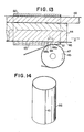
- a contact length L (mm) shown in Fig. 13 (where flattening of the electrode by the welding force is not taken into consideration) taken in the axial direction between the lapped portion 65 under welding and the rotary electrode 45 be present in the area R shown in Fig. 12, i.e., be from 3 to 10 mm, and desirably be present in the area R', i.e., be from 4 to 8 mm. That is, it is preferable that the welding pitch P (mm) and contact length L (mm) be within the ranges defined by the following expressions (3) and (4):
- the radius of the rotary electrode 45 be 50 mm or above, these electrodes be cooled (normally with water), and wire electrodes (46, 47) be used for preventing the surfaces of the electrodes from wearing.
- Elimination of the pitting 48 and splashes in forming a weld having the continuous heat affected zone 2 under the welding conditions described above requires use of a welding current with a waveform having a crest factor which satisfies the above-mentioned expression (1), and preferably the following expression (la), that is, such a waveform as exemplified in Fig. 11:
- the value of Ip/Ie is smaller than 1.5, the pitting 48 tends to be produced.
- the crest factor of a sine wave is 1.41.
- the crest factor Ip/Ie is larger than 2.0, an instantaneous current becomes so large that an overheated zone develops and thus splashes tend to be produced.
- This invention is not restricted to the embodiments described above and, for example, is applicable to a variety of surface treated steel sheets including tinplate with a normal tin coating weight.
- a blank of a 0.22 mm thick tinfree steel with a 100 mg/m 2 thick metallic chrome layer and a 15 mg/m 2 thick chromium oxide layer (in terms of chrome amount) was rounded (without removing the chromium surface layer over the margins of the blank) to form a 125.4 mm long can body preform 60 with a 0.35 mm wide lapped portion 65 and 65.3 mm inner diameter as shown in Fig. 13.
- the lapped portion 65 of the can body preform 60 was mash seam welded by means of an elongated electrode 44 and a rotary electrode 45 with 75 mm radius via wire electrodes 46 and 47 each formed of an about 2 mm wide flat rolled, annealed copper wire with an oval section and a flat surface abutting against the lapped portion, under the welding conditions mentioned below to make a welded can body 66 with a 0.26 mm thick weld 61 as shown in Fig. 14.
- the welding conditions are as follows:
- the welding force, welding speed, and frequency of welding - current are 100 kg, 60 m/min, and 400 Hz, respectively.
- the crest factor (Ip/Ie), the effective value (Ie) of the current, and the welding pitch were 1.75, 4.9 kA, and 1.25 mm, respectively.
- the welding current with the waveform 52 is preferably produced as described below.
- a rectangular wave current supply 55, an SCR circuit 56, and a primary coil 57a of a welding transformer 57 are connected in series to constitute a power circuit.
- Reference numbers 55a and 56a designates control circuits of the supply 55 and SCR circuit 56, respectively.
- the pover supply 55 is so constructed as to generate a voltage uith a rectangular waveform 53 shown in Fig. 11 in a broken line.
- a secondary coil 57b of the welding transformer 57 is connected to an elongated electrode 44 and a rotary electrode 45.
- turning on the SCR circuit 56 causes a welding current with the waveform 52 to flow through the electrodes 44 and 45.
- the crest factor Ip/Ie of the uelding current can be set by changing a length t 0 of the period during which the welding current 52 is zero and/or a length t of the period during which the supply voltage 53 is zero by adjusting the control circuits 56a and 55a, respectively.
- the effective value Ie of the welding current can be set by changing a peak value vp by adjusting the control circuit 55a.
- FIG. 16 The microscopic structure of the section (magnification, 50; etched with 5% alcoholic solution of picric acid for 2 minutes) of a weld 61 thus obtained in the longitudinal direction thereof is shown in Fig. 16.
- a heat affected zone 62 is continuously and substantially uniformly formed in the longitudinal direction of the weld 61. There is none of surface pitting.
- the microscopic sectional structure of the weld 41 formed with the sinusoidal welding current is shown in Fig. 10. While the heat affected zone is continuous, pittings are observed therein.
- a thin-nickel-plated sheet of 0.24 mm thick uith nickel of 600 mg/m 2 and chromium oxide thereon of 12 mg/m 2 (in terms of chrome amount) was allowed its inner and outer surfaces to be applied with so-called margin coating of an epoxy phenolic lacquer and with so-called margin printing of a printing ink, respectively, except for the areas to be welded, and then baked. Thereafter the sheet was cut into blanks to form can body preforms of 125.5 mm long and 65.3 mm diameter and having a lapped portion of 0.35 mm wide.
- the lapped portions of the can body preforms were mash seam welded by a water cooled, elongated electrode and a water cooled rotary electrode (with a 100 mm radius) opposed to the inner and outer surfaces of each lapped portion, respectively, via planetary electrodes (each having a width of 2 mm and a flat surface abutting against the lapped portion) formed from annealed copper wires uith oval sections, under the welding conditions mentioned in TABLE 1 to prepare welded can bodies Nos. 1, 2 and 3.
- the lapped portion of the can body preform was mash seam welded in the same manner as above under the welding conditions mentioned in TABLE 1, except for the use of outer and inner rotary electrodes with 110 mm and 60 mm diameters, respectively, opposed to each other, to prepare another welded can body No. 4.
- each welded can body taken in the circumferential direction of the can body and in the longitudinal direction of the weld was observed under a metalloscope. And whether a heat effected zone was exposed to the surface of the weld and was continuous in the longitudinal direction thereof were examined.
- the results are shown in TABLE 1. Further, with regard to the can bodies No's. 1 and 4, the microscopic structures (magnification, X50) etched with 5% alcoholic solution of picric acid for 2 minutes are shown in Figs. 1, 2 and Figs. 3, 4, respectively.
- epoxy phenolic lacquer was coated on the inner surface of the veld of each can body in about 7 mm width so that the dried coated film be from 10 to 20 ⁇ m thick, and baked. Thereafter eight- multi-beads of 4 mm deep and 10 mm long in the axial direction and flange portions were formed. A tinfree steel bottom end with its inner surface coated uith epoxy phenolic lacquer was double seamed in a normal manner to form a vacant can.
- the vacant cans filled with pickled mackerel- tomato were double seamed with the same tinfree steel lids as the above-mentioned bottom end and retort-sterilized at 116°C for 90 minutes. After the cans had been stored at 50°C for 6 months, the number of leaked cans per 1000 cans was determined, and the state of corrosion of the inner surfaces of the welds was examined. TABLE 1 shows the results.
- welded can bodies No. 5 according to this invention and No. 6 of a comparative example were prepared in the same manner as Example 2 and Comparative Example 1, under the welding conditions shown in TABLE 2.
- the exposure and continuity of the heat affected zone, corrosion resistance, and sealability were evaluated in the same manner as in Example 2. The results are shown in TABLE 2.
- the microscopic structures (magnification, X50) etched with 5% alcoholic solution of picric acid for 2 minutes are shown in Figs. 5, 6 and Figs. 7, 8; respectively.
Landscapes
- Engineering & Computer Science (AREA)
- Mechanical Engineering (AREA)
- Arc Welding In General (AREA)
- Rigid Pipes And Flexible Pipes (AREA)
- Butt Welding And Welding Of Specific Article (AREA)
Applications Claiming Priority (4)
| Application Number | Priority Date | Filing Date | Title |
|---|---|---|---|
| JP58165230A JPS6056490A (ja) | 1983-09-09 | 1983-09-09 | 溶接缶胴体の製造方法 |
| JP165230/83 | 1983-09-09 | ||
| JP16522983A JPS6058337A (ja) | 1983-09-09 | 1983-09-09 | 溶接缶胴体 |
| JP165229/83 | 1983-09-09 |
Publications (1)
| Publication Number | Publication Date |
|---|---|
| EP0134724A1 true EP0134724A1 (fr) | 1985-03-20 |
Family
ID=26490036
Family Applications (1)
| Application Number | Title | Priority Date | Filing Date |
|---|---|---|---|
| EP84306097A Withdrawn EP0134724A1 (fr) | 1983-09-09 | 1984-09-06 | Corps de boîte soudé et procédé pour sa fabrication |
Country Status (3)
| Country | Link |
|---|---|
| EP (1) | EP0134724A1 (fr) |
| KR (1) | KR890002769B1 (fr) |
| AU (1) | AU554748B2 (fr) |
Cited By (4)
| Publication number | Priority date | Publication date | Assignee | Title |
|---|---|---|---|---|
| EP0802011A3 (fr) * | 1996-04-19 | 1998-02-04 | Elpatronic Ag | Procédé pour relier deux feuilles métalliques |
| CN102653037A (zh) * | 2011-03-03 | 2012-09-05 | 通用汽车环球科技运作有限责任公司 | 复合产品 |
| RU2475680C2 (ru) * | 2007-11-23 | 2013-02-20 | Бсх Бош Унд Сименс Хаусгерете Гмбх | Устройство управления для бытового прибора |
| CN116652441A (zh) * | 2023-07-17 | 2023-08-29 | 杭州吴杭包装材料有限公司 | 一种桶体全自动焊缝机 |
Citations (3)
| Publication number | Priority date | Publication date | Assignee | Title |
|---|---|---|---|---|
| US3654422A (en) * | 1966-07-26 | 1972-04-04 | Continental Can Co | Square wave resistance welding |
| US4334138A (en) * | 1979-08-06 | 1982-06-08 | Toyo Seikan Kaisha, Limited | Method of electric welding tinfree cans |
| US4376884A (en) * | 1980-07-30 | 1983-03-15 | American Can Company | Closed loop control of continuous seam resistance heated forge welding cylinders |
-
1984
- 1984-08-29 KR KR1019840005269A patent/KR890002769B1/ko not_active Expired
- 1984-09-04 AU AU32705/84A patent/AU554748B2/en not_active Ceased
- 1984-09-06 EP EP84306097A patent/EP0134724A1/fr not_active Withdrawn
Patent Citations (3)
| Publication number | Priority date | Publication date | Assignee | Title |
|---|---|---|---|---|
| US3654422A (en) * | 1966-07-26 | 1972-04-04 | Continental Can Co | Square wave resistance welding |
| US4334138A (en) * | 1979-08-06 | 1982-06-08 | Toyo Seikan Kaisha, Limited | Method of electric welding tinfree cans |
| US4376884A (en) * | 1980-07-30 | 1983-03-15 | American Can Company | Closed loop control of continuous seam resistance heated forge welding cylinders |
Cited By (6)
| Publication number | Priority date | Publication date | Assignee | Title |
|---|---|---|---|---|
| EP0802011A3 (fr) * | 1996-04-19 | 1998-02-04 | Elpatronic Ag | Procédé pour relier deux feuilles métalliques |
| US6011236A (en) * | 1996-04-19 | 2000-01-04 | Elpatronic Ag | Method and apparatus for joining two metal foils together |
| RU2475680C2 (ru) * | 2007-11-23 | 2013-02-20 | Бсх Бош Унд Сименс Хаусгерете Гмбх | Устройство управления для бытового прибора |
| CN102653037A (zh) * | 2011-03-03 | 2012-09-05 | 通用汽车环球科技运作有限责任公司 | 复合产品 |
| CN102653037B (zh) * | 2011-03-03 | 2015-04-29 | 通用汽车环球科技运作有限责任公司 | 复合产品 |
| CN116652441A (zh) * | 2023-07-17 | 2023-08-29 | 杭州吴杭包装材料有限公司 | 一种桶体全自动焊缝机 |
Also Published As
| Publication number | Publication date |
|---|---|
| KR890002769B1 (ko) | 1989-07-28 |
| AU554748B2 (en) | 1986-09-04 |
| KR850002067A (ko) | 1985-05-06 |
| AU3270584A (en) | 1985-03-14 |
Similar Documents
| Publication | Publication Date | Title |
|---|---|---|
| EP0194608A1 (fr) | Procédé de soudage à recouvrement d'un flan de boîte en tôle ou similaire | |
| US4595326A (en) | Method of making welded can body | |
| EP0134724A1 (fr) | Corps de boîte soudé et procédé pour sa fabrication | |
| EP0038646B1 (fr) | Procédé pour fabriquer des boîtes soudées | |
| KR890003098B1 (ko) | 용접관동체(溶接缶胴體)의 제조방법 | |
| US4719329A (en) | Can body and method of making the same | |
| US5389451A (en) | Laminated steel sheet for welded can | |
| JP2806249B2 (ja) | 大型角形缶およびその製造方法 | |
| US5064982A (en) | Electric resistance seam welding method | |
| JP3212136B2 (ja) | 溶接缶胴を有する缶体 | |
| DE69112464T2 (de) | Verfahren zum Schweissen von emaillierten Gegenständen und Produkt dafür. | |
| JPS6135280B2 (fr) | ||
| WO1986003442A1 (fr) | Procede de soudage continu par resistance electrique | |
| JPS632712B2 (fr) | ||
| KR850001367B1 (ko) | 틴. 프리이. 스티일(tin free steel)용접캔의 제조법 | |
| JPS6330998B2 (fr) | ||
| KR850001365B1 (ko) | 용접캔의 제조법 | |
| JPH0343947B2 (fr) | ||
| JPS59209490A (ja) | 溶接缶胴体 | |
| JPH072998B2 (ja) | 溶接缶胴 | |
| JPH01104480A (ja) | 溶接缶胴の製造方法 | |
| JPS6058337A (ja) | 溶接缶胴体 | |
| JPS56105878A (en) | Production of corrosion-resistant welded can | |
| JPS61104087A (ja) | 塗装性能、耐食性能にすぐれた電気抵抗シ−ム溶接缶 | |
| Burns | Aircraft Spotwelding Efforts Benefit Many Industries |
Legal Events
| Date | Code | Title | Description |
|---|---|---|---|
| PUAI | Public reference made under article 153(3) epc to a published international application that has entered the european phase |
Free format text: ORIGINAL CODE: 0009012 |
|
| 17P | Request for examination filed |
Effective date: 19841214 |
|
| AK | Designated contracting states |
Designated state(s): CH DE FR GB LI |
|
| 17Q | First examination report despatched |
Effective date: 19860625 |
|
| STAA | Information on the status of an ep patent application or granted ep patent |
Free format text: STATUS: THE APPLICATION IS DEEMED TO BE WITHDRAWN |
|
| 18D | Application deemed to be withdrawn |
Effective date: 19870423 |
|
| RIN1 | Information on inventor provided before grant (corrected) |
Inventor name: ISHIBASHI, KAZUHISA Inventor name: MATSUBAYASHI, HIROSHI Inventor name: MATSUNO, KENJI Inventor name: KUSE, KAZUMA |