EP0134737B1 - Unterwassersaugnapf vom Ansaug-Unterdrucktyp - Google Patents
Unterwassersaugnapf vom Ansaug-Unterdrucktyp Download PDFInfo
- Publication number
- EP0134737B1 EP0134737B1 EP19840401515 EP84401515A EP0134737B1 EP 0134737 B1 EP0134737 B1 EP 0134737B1 EP 19840401515 EP19840401515 EP 19840401515 EP 84401515 A EP84401515 A EP 84401515A EP 0134737 B1 EP0134737 B1 EP 0134737B1
- Authority
- EP
- European Patent Office
- Prior art keywords
- wall
- suction cup
- underwater
- skirt
- watertightness
- Prior art date
- Legal status (The legal status is an assumption and is not a legal conclusion. Google has not performed a legal analysis and makes no representation as to the accuracy of the status listed.)
- Expired
Links
Images


Classifications
-
- B—PERFORMING OPERATIONS; TRANSPORTING
- B63—SHIPS OR OTHER WATERBORNE VESSELS; RELATED EQUIPMENT
- B63C—LAUNCHING, HAULING-OUT, OR DRY-DOCKING OF VESSELS; LIFE-SAVING IN WATER; EQUIPMENT FOR DWELLING OR WORKING UNDER WATER; MEANS FOR SALVAGING OR SEARCHING FOR UNDERWATER OBJECTS
- B63C7/00—Salvaging of disabled, stranded, or sunken vessels; Salvaging of vessel parts or furnishings, e.g. of safes; Salvaging of other underwater objects
- B63C7/16—Apparatus engaging vessels or objects
- B63C7/22—Apparatus engaging vessels or objects using electromagnets or suction devices
Definitions
- the technical sector of the present invention is that of underwater works, and more particularly devices aimed at producing solid attachment points on an underwater wall.
- Suction cups of different types have been used for a long time to achieve these solid support points.
- the first principle is generally used for the fixing and the maintenance of the explosive charges of destruction but their effectiveness is limited in time (and strongly depends on the care brought to their installation) and their force of adhesion is rather weak. They also require a surface cleaned beforehand.
- the second principle is used for the attachment of robots or machining systems.
- the magnetic suction cups are not very effective, require careful cleaning of the magnetic walls and their weight allows only horizontal applications downwards.
- the third principle is also unsatisfactory since it is not very effective due to the absence of skirts. In addition, this is heavy and bulky equipment.
- a last principle (FR-A-2 071 477) consists in using suction cups of the vacuum type maintained by a permanent pumping means for possible leaks, corresponding to a suction cup according to the preamble of claim 1.
- the object of the invention is to provide a suction cup of the latter type (with maintained vacuum) which is portable, therefore of low weight, but retains a large autonomy without the addition of energy or fluid from a carrier boat.
- a feature of the invention is to include the batteries and the motor 2 driving the pump 9 inside a sealed enclosure 7 without opening towards the pump, which ensures better sealing of the electrical circuit and batteries, this being permitted by virtue of the motor-pump connection produced through the sealed wall of the enclosure 7 without opening of the latter by means of a magnetic coupling.
- the skirt is made of neoprene.
- the sealing skirt 10 is a single-walled skirt, interchangeable.
- the sealing skirt 10 has a double wall with a profile suitable for holding plates before welding, the wall with internal profile 13 being longer than the external wall 12 and the two walls each having a variation. 19 in their length over part of their circumference, the variation in length being a function of the thickness of the plate to be welded,
- the sealing skirt 10 is double-walled, the profile of which is suitable for lifting spherical objects, the internal wall 13 being either shorter or the same length as the external wall 12 and the skirt 10 being interchangeable according to the extent of the variation in the diameters of the various spherical objects to be lifted.
- Another object of the invention is to provide an autonomous device for assisting the progression underwater of a diver along a wall despite the presence of significant sea currents, the device comprising two suction cups according to the invention used alternately.
- the suction cups may include a means of simultaneous action of stopping the engine and putting the vacuum bell of the suction cup at ambient pressure.
- Another object of the invention is to achieve by means of the suction cups according to the invention an underwater workshop comprising a platform allowing the laying of heavy loads or tools, this underwater workshop can be applied in any place under the hull of a ship by means of the aforementioned suction cups, to assist a diver carrying out repairs under the hull and ensuring off-shore work.
- the underwater suction cup can include a safety device triggering the operation of the pump 9 at a predetermined depth.
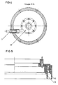
- the underwater suction cup is presented according to FIG. 1.
- the sealed enclosure 7 of the suction cup contains the pump 9 and the motor 2, the drive of the pump 9 by the motor 2 being done by means of the magnetic coupling 8.
- the motor is started manually using the contactor 4, and thanks to the safety device 11 (see fig. 2 and 9) triggering at a predetermined depth.
- the contactor 4 is engaged, the motor 2 is supplied, either by the internal batteries 3, or by means of the external power connector 6.
- a vacuum by suction is then created in the bell formed by the skirt 10, the pump 9 being provided with exhaust 1.
- This pump 9 differs from vacuum pumps by air suction in the following way: it works by only sucking water, which is also its lubricating liquid and can maintain a significant vacuum inside of the bell formed by the skirt 10, even in the absence of flow. Sealing is achieved thanks to the neoprene skirt 10. A skirt holder allows its interchangeability. Finally, to allow good maneuverability of the suction cup by divers, it is provided with a handle 5.
- the underwater suction cup according to the second variant is presented according to FIG. 5.
- the skirt is provided with two walls 12 and 13 substantially of the same length, which makes it possible to obtain a better seal in the case where one of the two skirts would be badly positioned.
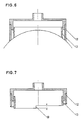
- the wall 13 is longer than the wall 12 (see for example the right part of FIG. 7).
- the plunger by applying the suction cup against an underwater wall, only brings the wall into contact with the latter 13. Adhesion is then achieved, but the wall 13 may not be perfectly positioned and leaks remain .
- the plunger having released the handle 5, can then perfectly position the wall 12, the latter not having yet adhered to the underwater wall.
- This principle has the enormous advantage of avoiding the diver during an imperfect adhesion to the wall 12, having to start the whole maneuver again, and having a perfect seal, the plunger having all the time necessary to perform positioning. wall 12.
- the skirt shown in Figure 7 is provided with a wall 13 longer than the wall 12.
- the variant of the underwater suction cup shown in Figure 7 is also suitable for holding plates before welding.
- the two walls, of unequal length each have a variation in their length over part of their circumference. This variation corresponds to the thickness of the plate to be welded and can range, while guaranteeing a perfect seal, up to a maximum of 12 mm.
- Figure 6 shows the variant of an underwater suction cup suitable for lifting spherical objects.
- the two walls 12 and 13 are of different length, the wall 12 being longer than the wall 13 so that the end of the two walls is arranged on the same sphere.
- the adhesion of the two walls will be carried out in a perfect manner, the end of the two walls also being bevelled to allow total sealing.
- the wall 13 will adhere first, thus allowing the plunger to perfectly position the wall 12.
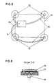
- the basic principle of the underwater suction cup can be adapted as required.
- the device shown in FIG. 8 comprises a single vacuum pump 9 connected by means of flexible pipes 15 to different vacuum chambers provided with single or double walled sealing skirts.
- the suction cups are connected together by a rigid frame 14. This device allows for example to fix along an underwater hull a cleaning robot or other automatic mechanisms.
- specific skirts can be adapted to each particular case.
- FIG. 9 shows the safety device triggering the pump at a certain depth.
- This device is composed of a plate with holes 16 in which the water establishes a pressure acting on the membrane 17. The latter, by deforming, will establish contact at a certain pressure corresponding to a predetermined immersion depth, with relay 18 connected in series in the control circuit between the contactor and the motor. Thus the engine will be started and the pump will come into action.
- the suction cup In lateral traction, the suction cup is pulled out between 50 daN and 100 daN depending on the surface condition.
- FIGS 10 and 11 show a variant of space-saving suction cup which can be intended to aid the progression of a diver along a boat hull in the presence of a sea current.
- the control means 20 is made in the form of an on / off switch 22 for the motor 2, actuated by a sealed push button 23 acting against a spring 24, the push button 23 being integral with a rod 25 operating a valve 21 which allows, by pressing on the pusher, to put the interior of the vacuum bell 10 into communication with the marine environment through an adjustment 26.
- the batteries 3 for supplying the engine 2 may not be placed inside the sealed enclosure 7 but be placed on the compressed air bottles 27 of the plunger (see FIG. 12). , the batteries 3 then being connected to the motor 2 by cables 28.
- the invention allows the realization of an autonomous means of assistance with the progression under water of a plunger along a wall against currents of 1 to 2 knots.
- the diver holds in each hand a suction cup carrying a built-in battery or connected by a cable 28 to a battery 3 supported by its compressed air bottles.
- the plunger presses a suction cup against the wall by releasing the control means 20; the pump then operates while the vacuum bell is closed by the valve 21 and the suction cup becomes vacuum.
- the diver places a second suction cup further on the wall and detaches the first suction cup by pressing on the control means 20, which has the effect of stopping the motor 2 and putting the bell 10 and the sea in communication .
- Lightened suction cups weighing less than 3 daN made according to the invention thus made it possible for a diver to progress or work with an autonomy of more than an hour in currents of 2 knots.
- an underwater workshop is produced by means of a platform scaffolding 30 comprising expandable horizontal and vertical tubes 31 at the end of which suction cups 33 can be arranged according to the invention.
- the suction cups 33 are arranged at the end of the horizontal or vertical tubes 31, depending on the inclination of the hull or of the wall on which the underwater workshop is to be fixed. To allow better adaptability of the assembly, the suction cups are mounted to rotate on the arms 31 by means of rotation axes 32.
- the load capacity of the platform 30 is under water of 1,000 daN with an autonomy of one hour.
- external batteries can be used on the carrier boat to which the suction cups 33 will be connected.
- the submarine workshop thus produced has an important advantage compared to previous achievements which were fixed under the ship using two straps passed from one edge to the other.
- the implementation time of these prior devices required approximately four hours of work for two divers and three men on board while the device according to the present invention requires only half an hour of work for 2 divers and a man of edge.
Landscapes
- Physics & Mathematics (AREA)
- Electromagnetism (AREA)
- Engineering & Computer Science (AREA)
- Mechanical Engineering (AREA)
- Ocean & Marine Engineering (AREA)
- Manipulator (AREA)
- Toys (AREA)
Claims (9)
Applications Claiming Priority (2)
| Application Number | Priority Date | Filing Date | Title |
|---|---|---|---|
| FR8311980A FR2549550B1 (fr) | 1983-07-20 | 1983-07-20 | Ventouse sous-marine du type a depression par aspiration |
| FR8311980 | 1983-07-20 |
Publications (2)
| Publication Number | Publication Date |
|---|---|
| EP0134737A1 EP0134737A1 (de) | 1985-03-20 |
| EP0134737B1 true EP0134737B1 (de) | 1986-11-12 |
Family
ID=9290964
Family Applications (1)
| Application Number | Title | Priority Date | Filing Date |
|---|---|---|---|
| EP19840401515 Expired EP0134737B1 (de) | 1983-07-20 | 1984-07-19 | Unterwassersaugnapf vom Ansaug-Unterdrucktyp |
Country Status (3)
| Country | Link |
|---|---|
| EP (1) | EP0134737B1 (de) |
| DE (1) | DE3461269D1 (de) |
| FR (1) | FR2549550B1 (de) |
Families Citing this family (4)
| Publication number | Priority date | Publication date | Assignee | Title |
|---|---|---|---|---|
| WO1988003110A1 (en) * | 1986-10-28 | 1988-05-05 | Hind, Raymond, Stenton | Surface and underwater handling device |
| FR2672650B1 (fr) * | 1991-02-08 | 1993-08-27 | Devco Ingenierie | Ventouse dynamique. |
| CN110873159A (zh) * | 2019-11-18 | 2020-03-10 | 上海海事大学 | 一种水下丝杠滑块传动装置 |
| CN117087839A (zh) * | 2023-08-24 | 2023-11-21 | 交通运输部上海打捞局 | 一种水下利用仿章鱼触手吸粘打捞的工艺方法 |
Family Cites Families (10)
| Publication number | Priority date | Publication date | Assignee | Title |
|---|---|---|---|---|
| US2347491A (en) * | 1941-08-29 | 1944-04-25 | Lente Howard Otis | Salvaging apparatus and system |
| DE866324C (de) * | 1951-04-25 | 1953-02-09 | Gottfried Dr Cremer | Saugkopf fuer Vakuum-Transportanlagen, insbesondere fuer keramische Formlinge |
| US2876026A (en) * | 1952-11-24 | 1959-03-03 | Mancini Luigi | Suction cup device for equipment to be applied onto submersed surfaces, such as hull plates and the like |
| FR71519E (fr) * | 1957-05-07 | 1960-01-05 | France Etat | Ventouse sous-marine à piston |
| US3348517A (en) * | 1966-02-18 | 1967-10-24 | Hydronautics | Underwater suction anchors |
| US3354856A (en) * | 1966-03-16 | 1967-11-28 | Joseph R Annibale | Submerged object lifting device |
| US3361469A (en) * | 1966-06-01 | 1968-01-02 | Budd Co | Fluid pressure controlled holding device for a lift unit |
| FR1547625A (fr) * | 1967-10-13 | 1968-11-29 | Dispositif d'ancrage | |
| FR2071477A5 (de) * | 1969-12-30 | 1971-09-17 | Wetdocking France Sa | |
| US4154185A (en) * | 1977-10-11 | 1979-05-15 | The United States Of America As Represented By The Secretary Of The Navy | Submersible apparatus for evacuating seawater from suction-type work-handling gripper members |
-
1983
- 1983-07-20 FR FR8311980A patent/FR2549550B1/fr not_active Expired
-
1984
- 1984-07-19 EP EP19840401515 patent/EP0134737B1/de not_active Expired
- 1984-07-19 DE DE8484401515T patent/DE3461269D1/de not_active Expired
Also Published As
| Publication number | Publication date |
|---|---|
| FR2549550A1 (fr) | 1985-01-25 |
| FR2549550B1 (fr) | 1987-05-22 |
| DE3461269D1 (en) | 1987-01-02 |
| EP0134737A1 (de) | 1985-03-20 |
Similar Documents
| Publication | Publication Date | Title |
|---|---|---|
| CA2987680C (fr) | Robot de nettoyage de piscine autonome | |
| EP2922748B1 (de) | Schwimmkörper zur entnahme flüssiger proben | |
| EP3253648B1 (de) | Vorrichtung zur verwendung beim transport und/oder der handhabung von material in einer unterwasserumgebung zur durchführung von arbeiten | |
| FR2542243A1 (fr) | Porte-outil pour robot industriel | |
| CA1156689A (fr) | Vehicule sous-marin de dragage et de remontee de mineraux a grande profondeur | |
| FR2762825A1 (fr) | Procede et dispositif de raccordement de navires | |
| WO2011015786A1 (fr) | Robot automatique de nettoyage de carenes | |
| EP0134737B1 (de) | Unterwassersaugnapf vom Ansaug-Unterdrucktyp | |
| EP2726367A1 (de) | Unterwasserfahrzeug zum reinigen von unterwasserflächen | |
| EP4183955A1 (de) | Autonomer propellersauger für die reinigung von schwimmbädern | |
| FR2529131A1 (fr) | Robot capable de se deplacer sur parois inclinees ou verticales | |
| FR2620937A1 (fr) | Dispositif flottable pour bain a bulles | |
| FR2684065A1 (fr) | Bateau recuperateur d'objets flottants. | |
| CN109030089B (zh) | 手持式海底沙层保压保温取样装置及其使用方法 | |
| FR2672650A1 (fr) | Ventouse dynamique. | |
| FR3003483A1 (fr) | Dispositif de nettoyage de surfaces immergees | |
| FR2929589A1 (fr) | Esquif leger autopropulse pour porter secours en milieu aquatique | |
| FR3159143A1 (fr) | Système de déplacement redondant pour robot | |
| JP2004238905A (ja) | 泥土吸引装置 | |
| CN213535044U (zh) | 一种内河水域的水上危化品回收船 | |
| FR2591182A1 (fr) | Dispositif de commande d'un objet submerge remorque. | |
| FR3159142A1 (fr) | Propulseur à géométrie variable | |
| FR2850631A1 (fr) | Procede de recuperation d'une cargaison de liquides polluants a bord d'une epave | |
| FR2744558A1 (fr) | Procede et dispositif d'enlevement de residus en particulier pour la decontamination d'installations nucleaires | |
| FR2513212A1 (fr) | Engin d'intervention de plongeurs a faible profondeur |
Legal Events
| Date | Code | Title | Description |
|---|---|---|---|
| PUAI | Public reference made under article 153(3) epc to a published international application that has entered the european phase |
Free format text: ORIGINAL CODE: 0009012 |
|
| 17P | Request for examination filed |
Effective date: 19840802 |
|
| AK | Designated contracting states |
Designated state(s): BE DE GB IT NL SE |
|
| 17Q | First examination report despatched |
Effective date: 19860129 |
|
| ITF | It: translation for a ep patent filed | ||
| GRAA | (expected) grant |
Free format text: ORIGINAL CODE: 0009210 |
|
| AK | Designated contracting states |
Kind code of ref document: B1 Designated state(s): BE DE GB IT NL SE |
|
| REF | Corresponds to: |
Ref document number: 3461269 Country of ref document: DE Date of ref document: 19870102 |
|
| PLBE | No opposition filed within time limit |
Free format text: ORIGINAL CODE: 0009261 |
|
| STAA | Information on the status of an ep patent application or granted ep patent |
Free format text: STATUS: NO OPPOSITION FILED WITHIN TIME LIMIT |
|
| 26N | No opposition filed | ||
| ITTA | It: last paid annual fee | ||
| EAL | Se: european patent in force in sweden |
Ref document number: 84401515.6 |
|
| PGFP | Annual fee paid to national office [announced via postgrant information from national office to epo] |
Ref country code: GB Payment date: 19960709 Year of fee payment: 13 |
|
| PGFP | Annual fee paid to national office [announced via postgrant information from national office to epo] |
Ref country code: NL Payment date: 19960731 Year of fee payment: 13 |
|
| PGFP | Annual fee paid to national office [announced via postgrant information from national office to epo] |
Ref country code: BE Payment date: 19960812 Year of fee payment: 13 |
|
| PGFP | Annual fee paid to national office [announced via postgrant information from national office to epo] |
Ref country code: DE Payment date: 19960911 Year of fee payment: 13 |
|
| PGFP | Annual fee paid to national office [announced via postgrant information from national office to epo] |
Ref country code: SE Payment date: 19970625 Year of fee payment: 14 |
|
| PG25 | Lapsed in a contracting state [announced via postgrant information from national office to epo] |
Ref country code: GB Free format text: LAPSE BECAUSE OF NON-PAYMENT OF DUE FEES Effective date: 19970719 |
|
| PG25 | Lapsed in a contracting state [announced via postgrant information from national office to epo] |
Ref country code: SE Effective date: 19970720 |
|
| PG25 | Lapsed in a contracting state [announced via postgrant information from national office to epo] |
Ref country code: BE Free format text: LAPSE BECAUSE OF NON-PAYMENT OF DUE FEES Effective date: 19970731 |
|
| BERE | Be: lapsed |
Owner name: ETAT-FRANCAIS REPRESENTE PAR LE DELEGUE GENERAL P Effective date: 19970731 |
|
| PG25 | Lapsed in a contracting state [announced via postgrant information from national office to epo] |
Ref country code: NL Free format text: LAPSE BECAUSE OF NON-PAYMENT OF DUE FEES Effective date: 19980201 |
|
| GBPC | Gb: european patent ceased through non-payment of renewal fee |
Effective date: 19970719 |
|
| NLV4 | Nl: lapsed or anulled due to non-payment of the annual fee |
Effective date: 19980201 |
|
| PG25 | Lapsed in a contracting state [announced via postgrant information from national office to epo] |
Ref country code: DE Free format text: LAPSE BECAUSE OF NON-PAYMENT OF DUE FEES Effective date: 19980401 |
|
| EUG | Se: european patent has lapsed |
Ref document number: 84401515.6 |