EP0134894A2 - Montage interne de réacteurs multiphases thermiques et sous pression, spécialement de réacteurs d'hydrogénation en suspension - Google Patents
Montage interne de réacteurs multiphases thermiques et sous pression, spécialement de réacteurs d'hydrogénation en suspension Download PDFInfo
- Publication number
- EP0134894A2 EP0134894A2 EP84105319A EP84105319A EP0134894A2 EP 0134894 A2 EP0134894 A2 EP 0134894A2 EP 84105319 A EP84105319 A EP 84105319A EP 84105319 A EP84105319 A EP 84105319A EP 0134894 A2 EP0134894 A2 EP 0134894A2
- Authority
- EP
- European Patent Office
- Prior art keywords
- reactors
- pressure
- reactor
- gas
- pendulum line
- Prior art date
- Legal status (The legal status is an assumption and is not a legal conclusion. Google has not performed a legal analysis and makes no representation as to the accuracy of the status listed.)
- Granted
Links
- 238000005984 hydrogenation reaction Methods 0.000 title claims description 16
- 238000000034 method Methods 0.000 claims abstract description 17
- 239000007787 solid Substances 0.000 claims abstract description 10
- 239000003921 oil Substances 0.000 claims abstract description 7
- 230000010354 integration Effects 0.000 claims abstract description 4
- 238000006243 chemical reaction Methods 0.000 claims description 9
- 239000003245 coal Substances 0.000 claims description 8
- 238000009835 boiling Methods 0.000 claims description 3
- 238000000926 separation method Methods 0.000 claims description 2
- 239000007789 gas Substances 0.000 description 26
- 239000012071 phase Substances 0.000 description 11
- 239000007788 liquid Substances 0.000 description 8
- 239000010742 number 1 fuel oil Substances 0.000 description 7
- 239000000376 reactant Substances 0.000 description 6
- 239000000203 mixture Substances 0.000 description 5
- 239000007795 chemical reaction product Substances 0.000 description 3
- 150000002430 hydrocarbons Chemical class 0.000 description 3
- 239000011541 reaction mixture Substances 0.000 description 3
- 239000012808 vapor phase Substances 0.000 description 3
- 239000004215 Carbon black (E152) Substances 0.000 description 2
- 238000004939 coking Methods 0.000 description 2
- 229930195733 hydrocarbon Natural products 0.000 description 2
- 230000007257 malfunction Effects 0.000 description 2
- 238000010327 methods by industry Methods 0.000 description 2
- 239000000126 substance Substances 0.000 description 2
- UFHFLCQGNIYNRP-UHFFFAOYSA-N Hydrogen Chemical compound [H][H] UFHFLCQGNIYNRP-UHFFFAOYSA-N 0.000 description 1
- 238000009825 accumulation Methods 0.000 description 1
- 239000003054 catalyst Substances 0.000 description 1
- 239000000919 ceramic Substances 0.000 description 1
- DGLFSNZWRYADFC-UHFFFAOYSA-N chembl2334586 Chemical compound C1CCC2=CN=C(N)N=C2C2=C1NC1=CC=C(C#CC(C)(O)C)C=C12 DGLFSNZWRYADFC-UHFFFAOYSA-N 0.000 description 1
- 239000003250 coal slurry Substances 0.000 description 1
- 239000000571 coke Substances 0.000 description 1
- 238000009833 condensation Methods 0.000 description 1
- 230000005494 condensation Effects 0.000 description 1
- 238000001816 cooling Methods 0.000 description 1
- 238000005260 corrosion Methods 0.000 description 1
- 230000007797 corrosion Effects 0.000 description 1
- 238000010586 diagram Methods 0.000 description 1
- 238000011010 flushing procedure Methods 0.000 description 1
- 239000000295 fuel oil Substances 0.000 description 1
- 238000010438 heat treatment Methods 0.000 description 1
- 239000001257 hydrogen Substances 0.000 description 1
- 229910052739 hydrogen Inorganic materials 0.000 description 1
- 238000010348 incorporation Methods 0.000 description 1
- 239000000463 material Substances 0.000 description 1
- 239000002245 particle Substances 0.000 description 1
- 239000010734 process oil Substances 0.000 description 1
- 230000001105 regulatory effect Effects 0.000 description 1
- 238000005201 scrubbing Methods 0.000 description 1
- 238000007789 sealing Methods 0.000 description 1
- 230000005654 stationary process Effects 0.000 description 1
- 230000008961 swelling Effects 0.000 description 1
- 230000005514 two-phase flow Effects 0.000 description 1
Images



Classifications
-
- B—PERFORMING OPERATIONS; TRANSPORTING
- B01—PHYSICAL OR CHEMICAL PROCESSES OR APPARATUS IN GENERAL
- B01J—CHEMICAL OR PHYSICAL PROCESSES, e.g. CATALYSIS OR COLLOID CHEMISTRY; THEIR RELEVANT APPARATUS
- B01J3/00—Processes of utilising sub-atmospheric or super-atmospheric pressure to effect chemical or physical change of matter; Apparatus therefor
- B01J3/002—Component parts of these vessels not mentioned in B01J3/004, B01J3/006, B01J3/02 - B01J3/08; Measures taken in conjunction with the process to be carried out, e.g. safety measures
-
- B—PERFORMING OPERATIONS; TRANSPORTING
- B01—PHYSICAL OR CHEMICAL PROCESSES OR APPARATUS IN GENERAL
- B01J—CHEMICAL OR PHYSICAL PROCESSES, e.g. CATALYSIS OR COLLOID CHEMISTRY; THEIR RELEVANT APPARATUS
- B01J3/00—Processes of utilising sub-atmospheric or super-atmospheric pressure to effect chemical or physical change of matter; Apparatus therefor
- B01J3/04—Pressure vessels, e.g. autoclaves
- B01J3/046—Pressure-balanced vessels
-
- C—CHEMISTRY; METALLURGY
- C10—PETROLEUM, GAS OR COKE INDUSTRIES; TECHNICAL GASES CONTAINING CARBON MONOXIDE; FUELS; LUBRICANTS; PEAT
- C10G—CRACKING HYDROCARBON OILS; PRODUCTION OF LIQUID HYDROCARBON MIXTURES, e.g. BY DESTRUCTIVE HYDROGENATION, OLIGOMERISATION, POLYMERISATION; RECOVERY OF HYDROCARBON OILS FROM OIL-SHALE, OIL-SAND, OR GASES; REFINING MIXTURES MAINLY CONSISTING OF HYDROCARBONS; REFORMING OF NAPHTHA; MINERAL WAXES
- C10G1/00—Production of liquid hydrocarbon mixtures from oil-shale, oil-sand, or non-melting solid carbonaceous or similar materials, e.g. wood, coal
- C10G1/06—Production of liquid hydrocarbon mixtures from oil-shale, oil-sand, or non-melting solid carbonaceous or similar materials, e.g. wood, coal by destructive hydrogenation
- C10G1/065—Production of liquid hydrocarbon mixtures from oil-shale, oil-sand, or non-melting solid carbonaceous or similar materials, e.g. wood, coal by destructive hydrogenation in the presence of a solvent
Definitions
- the invention relates to the incorporation of a pressure reactor based on the floating bubble principle for thermal and pressure-loaded processes in which multi-phase reaction mixtures consisting of gases, liquids and solid particles are conducted.
- the conventional coal hydrogenation reactors have a ceramic lining to keep the outer pressure-bearing jacket at a low temperature.
- the disadvantage here is that the porous lining can be destroyed in the event of rapid pressure relief of the reactors.
- the reactor principle of the floating bubble has proven itself in chemical reactions that take place at elevated pressures and elevated temperatures.
- the reactor inner jacket consists of temperature and corrosion-resistant material.
- the process pressure is transferred to the outer reactor jacket, which is at a lower temperature level. This is done by a gas or liquid support medium, which is located between the two reactor jackets (annular space), which transfers the internal pressure to the outer pressure-bearing jacket and at the same time creates a temperature gradient between the inner and outer reactor jacket.
- a gas or liquid support medium which is located between the two reactor jackets (annular space), which transfers the internal pressure to the outer pressure-bearing jacket and at the same time creates a temperature gradient between the inner and outer reactor jacket.
- the two first-mentioned processes are also not readily applicable to a multiphase reactor with a continuous flow, the reactants of which tend to coke, for example if the residence time is long, since this would require a gas-carrying pressure compensation line from the reaction space to the support medium in the annular space. However, the latter can become blocked if this pressure compensation line is not constantly flushed by means of regulated gas flushing (complex and prone to failure).
- the invention has for its object to realize thermally and pressure-loaded multi-phase reactors according to the principle of the floating bubble - for example in a sump phase hydrogenation process - clogging of the annulus and expensive and fault-prone auxiliary devices are avoided.
- This object is achieved in that the multiphase reaction products flowing through one or more reactors are cooled after leaving the (last) reactor and condensed into solids-containing and condensed out in one or more separators Reaction products on the one hand and remaining gases / vapors on the other hand are separated, the gases / vapors path being connected to the annulus of the reactor (or the reactors) by means of a pendulum line. Since the pressure loss between the reactors and the separators is generally comparatively low, it is ensured that there is an immediate pressure equalization between the reaction space and the annular space not only in stationary operation, but also during load changes and malfunctions (e.g. rapid pressure drop in the reactor system). Additional auxiliary and control devices are not required.
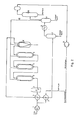
- FIG. 1 shows a procedure for integrating high-pressure reactors according to the invention (floating bubble principle).
- the coal pulp mixed with the process oil is pressed to a pressure of approx. 320 bar by means of high-pressure pump 1.
- the partially preheated hydrogenation gas in the heat exchanger 2 is fed to the coal slurry under 320 bar.
- the three-phase mixture, consisting of solids (coal, catalyst), oil and hydrogenation gas, is heated via heat exchanger 3 and a final heater 4 to the light-off temperature of the reactor (for example 420-460 ° C.).
- the three-phase reaction mixture flows through a plurality of hydrogenation reactors 5 and then passes into the hot separator 6, in which the gas / vapor phase (excess hydrogenation gas, reaction gases and vaporous coal oils) are drawn off under the bottom phase (higher-boiling oils and solids) and above.
- the gas / vapor phase is partially cooled by means of heat exchangers 3 and 2 (for example 240 ° C.), whereby some of the coal oils condense out. Both phases are separated from one another in the separator 7.
- the gas / vapor phase is cooled to almost ambient temperature (eg 40 ° C.) by means of a cooler 8, as a result of which the remaining coal oils condense out.
- the pendulum line is a connecting line that balances the pressure between the connected vessels.
- the pendulum line 12 which still contains oil vapors, for example in FIG. 1, the condensation of coal oil and the accumulation in line sinks is counteracted by heated lines or a cooler 13 above the separator 7.
- the process engineering justification for the integration of a pendulum line according to the invention into the path between the head of the hot separator 6 and the suction side of the compressor 11 lies in the fact that - for example the coal hydrogenation - the pressure loss between the reactors 5 and the separators 7, 9, 10 is comparatively low (for example 3-5 bar), so that an adequate, simultaneous pressure equalization between the interior of the reactor and the annular space occurs without additional control devices.
- the pendulum line can also be connected directly to the head-side outlet of the first separator 6 (FIG. 4). This further reduces the pressure difference between the interior and the annular space of the reaction vessels. However, a two-phase flow (free of solids) can then occur in the pendulum line, so that liquid also gets into the annular space. In this case s . process liquid also serve as a proppant in the annulus.
Landscapes
- Chemical & Material Sciences (AREA)
- Chemical Kinetics & Catalysis (AREA)
- Organic Chemistry (AREA)
- Engineering & Computer Science (AREA)
- Oil, Petroleum & Natural Gas (AREA)
- Life Sciences & Earth Sciences (AREA)
- Wood Science & Technology (AREA)
- General Chemical & Material Sciences (AREA)
- Production Of Liquid Hydrocarbon Mixture For Refining Petroleum (AREA)
Applications Claiming Priority (2)
| Application Number | Priority Date | Filing Date | Title |
|---|---|---|---|
| DE3323885A DE3323885A1 (de) | 1983-07-02 | 1983-07-02 | Verfahren zur prozesstechnischen einbindung von thermisch- und druckbelasteten mehrphasen-reaktoren speziell hydrierreaktoren in der sumpfphase |
| DE3323885 | 1983-07-02 |
Publications (3)
| Publication Number | Publication Date |
|---|---|
| EP0134894A2 true EP0134894A2 (fr) | 1985-03-27 |
| EP0134894A3 EP0134894A3 (en) | 1986-06-04 |
| EP0134894B1 EP0134894B1 (fr) | 1988-09-14 |
Family
ID=6202984
Family Applications (1)
| Application Number | Title | Priority Date | Filing Date |
|---|---|---|---|
| EP84105319A Expired EP0134894B1 (fr) | 1983-07-02 | 1984-05-10 | Montage interne de réacteurs multiphases thermiques et sous pression, spécialement de réacteurs d'hydrogénation en suspension |
Country Status (10)
| Country | Link |
|---|---|
| US (1) | US4555325A (fr) |
| EP (1) | EP0134894B1 (fr) |
| JP (1) | JPH0624621B2 (fr) |
| AU (1) | AU568859B2 (fr) |
| BR (1) | BR8403222A (fr) |
| CA (1) | CA1231656A (fr) |
| DE (2) | DE3323885A1 (fr) |
| PL (1) | PL146013B1 (fr) |
| SU (1) | SU1360589A3 (fr) |
| ZA (1) | ZA844752B (fr) |
Cited By (1)
| Publication number | Priority date | Publication date | Assignee | Title |
|---|---|---|---|---|
| EP0168301A1 (fr) * | 1984-06-18 | 1986-01-15 | Ashland Oil, Inc. | Procédé de préparation du fluorure de isobutyryle en phase vapeur-liquide et le réacteur approprié |
Families Citing this family (11)
| Publication number | Priority date | Publication date | Assignee | Title |
|---|---|---|---|---|
| JPS6022923B2 (ja) * | 1982-04-02 | 1985-06-05 | フランスベッド株式会社 | ソフアベツド装置 |
| US5277881A (en) * | 1992-09-14 | 1994-01-11 | Texaco Inc. | Hydrogen fluoride alkylation apparatus and vapor recovery method |
| USH2029H1 (en) * | 1993-11-01 | 2002-06-04 | Texaco Inc. | Environmental safety apparatus for airborne hydrogen fluoride recovery and method |
| US7906013B2 (en) * | 2006-12-29 | 2011-03-15 | Uop Llc | Hydrocarbon conversion process |
| US8529645B2 (en) * | 2007-10-03 | 2013-09-10 | Arizona Public Service Company | Hydrogasification reactor and method of operating same |
| US9279087B2 (en) | 2008-06-30 | 2016-03-08 | Uop Llc | Multi-staged hydroprocessing process and system |
| US8999141B2 (en) * | 2008-06-30 | 2015-04-07 | Uop Llc | Three-phase hydroprocessing without a recycle gas compressor |
| US8008534B2 (en) | 2008-06-30 | 2011-08-30 | Uop Llc | Liquid phase hydroprocessing with temperature management |
| US8518241B2 (en) * | 2009-06-30 | 2013-08-27 | Uop Llc | Method for multi-staged hydroprocessing |
| US8221706B2 (en) * | 2009-06-30 | 2012-07-17 | Uop Llc | Apparatus for multi-staged hydroprocessing |
| CN104474976A (zh) * | 2014-11-27 | 2015-04-01 | 常州市西屋自动化有限公司 | 压力平衡式反应器系统及其控制方法 |
Family Cites Families (15)
| Publication number | Priority date | Publication date | Assignee | Title |
|---|---|---|---|---|
| DE490558C (de) * | 1930-01-30 | Volkmar Haenig & Comp | Erhitzungsgefaess | |
| US1835425A (en) * | 1926-08-07 | 1931-12-08 | Standard Ig Co | Destructive hydrogenation of carbonaceous materials |
| US1894257A (en) * | 1927-05-28 | 1933-01-10 | Ig Farbenindustrie Ag | Production of liquid hydrocarbons |
| US2525276A (en) * | 1946-08-22 | 1950-10-10 | Hercules Powder Co Ltd | Method of cracking hydrocarbons |
| DE1542005A1 (de) * | 1951-01-28 | 1970-03-19 | Basf Ag | Hochdruckreaktor |
| US3520794A (en) * | 1968-03-29 | 1970-07-14 | Universal Oil Prod Co | Solvent extraction method |
| US3751228A (en) * | 1970-12-16 | 1973-08-07 | V Semenov | Apparatus for reforming hydrocarbons under pressure |
| CH604798A5 (fr) * | 1976-06-18 | 1978-09-15 | Bertrams Ag Hch | |
| DE2656726A1 (de) * | 1976-12-15 | 1978-06-22 | Otto & Co Gmbh Dr C | Roehrenreaktor zur durchfuehrung endothermer gasreaktionen |
| US4235841A (en) * | 1979-02-21 | 1980-11-25 | Autoclave Engineers, Inc. | Double chambered high pressure furnace |
| DE2943538A1 (de) * | 1979-10-27 | 1981-05-07 | Hermann Berstorff Maschinenbau Gmbh, 3000 Hannover | Verfahren und einrichtung zum hochdruck-abdichten des antriebsseitigen teils einer aufbereitungs- bzw. hydrierkammer fuer die hydrierung vonkohle mit wasserstoff zu kohlenwasserstoffen |
| US4343626A (en) * | 1980-02-19 | 1982-08-10 | Brennstoffinstitut Freiberg | Reactor for producing a carbon monoxide and hydrogen containing gas |
| US4357305A (en) * | 1981-03-17 | 1982-11-02 | The United States Of America As Represented By The United States Department Of Energy | Coal gasification vessel |
| US4454240A (en) * | 1981-11-02 | 1984-06-12 | Hri, Inc. | Catalyst regeneration process including metal contaminants removal |
| DE3263016D1 (en) * | 1981-11-09 | 1985-05-15 | Shell Int Research | Apparatus for gasifying finely divided fuels |
-
1983
- 1983-07-02 DE DE3323885A patent/DE3323885A1/de not_active Withdrawn
-
1984
- 1984-05-10 DE DE8484105319T patent/DE3473993D1/de not_active Expired
- 1984-05-10 EP EP84105319A patent/EP0134894B1/fr not_active Expired
- 1984-06-21 AU AU29593/84A patent/AU568859B2/en not_active Ceased
- 1984-06-22 PL PL1984248359A patent/PL146013B1/pl unknown
- 1984-06-22 ZA ZA844752A patent/ZA844752B/xx unknown
- 1984-06-29 BR BR8403222A patent/BR8403222A/pt not_active IP Right Cessation
- 1984-06-29 US US06/626,183 patent/US4555325A/en not_active Expired - Fee Related
- 1984-06-29 SU SU843758548A patent/SU1360589A3/ru active
- 1984-06-29 JP JP59133387A patent/JPH0624621B2/ja not_active Expired - Lifetime
- 1984-06-29 CA CA000457884A patent/CA1231656A/fr not_active Expired
Cited By (1)
| Publication number | Priority date | Publication date | Assignee | Title |
|---|---|---|---|---|
| EP0168301A1 (fr) * | 1984-06-18 | 1986-01-15 | Ashland Oil, Inc. | Procédé de préparation du fluorure de isobutyryle en phase vapeur-liquide et le réacteur approprié |
Also Published As
| Publication number | Publication date |
|---|---|
| PL248359A1 (en) | 1985-04-24 |
| AU568859B2 (en) | 1988-01-14 |
| EP0134894B1 (fr) | 1988-09-14 |
| AU2959384A (en) | 1985-01-24 |
| US4555325A (en) | 1985-11-26 |
| JPH0624621B2 (ja) | 1994-04-06 |
| BR8403222A (pt) | 1985-06-11 |
| PL146013B1 (en) | 1988-12-31 |
| DE3473993D1 (en) | 1988-10-20 |
| CA1231656A (fr) | 1988-01-19 |
| SU1360589A3 (ru) | 1987-12-15 |
| EP0134894A3 (en) | 1986-06-04 |
| ZA844752B (en) | 1985-05-29 |
| JPS6022923A (ja) | 1985-02-05 |
| DE3323885A1 (de) | 1985-01-03 |
Similar Documents
| Publication | Publication Date | Title |
|---|---|---|
| EP0134894B1 (fr) | Montage interne de réacteurs multiphases thermiques et sous pression, spécialement de réacteurs d'hydrogénation en suspension | |
| DE2934332C2 (de) | Verfahren zur katalytischen Synthese von Methanol | |
| DE69120118T2 (de) | Verfahren zur Methanolherstellung | |
| DE69105986T2 (de) | Ammoniaksyntheseapparat. | |
| DE3133893C2 (fr) | ||
| EP0320440A2 (fr) | Préchauffage de mélanges hydrocarbure/vapeur d'eau | |
| BE1029986B1 (de) | Verfahren zum Betreiben einer Ammoniakanlage und Anlage zur Herstellung von Ammoniak | |
| US4457829A (en) | Temperature control method for series-connected reactors | |
| EP0177676B1 (fr) | Réglage par récupération de la chaleur d'un procédé d'hydrogénation en suspension avec hydrogénation en phase gazeuse intégrée | |
| DE2504303A1 (de) | Verfahren und vorrichtung zur katalytischen umwandlung von kohlenwasserstoffen | |
| DE60110625T2 (de) | Reaktor zur chemischen umwandlung eines ausgangsmaterials mit wärmezufuhr und ausgangsmaterial/katalysator-querzirkulation | |
| DE2803985C2 (de) | Verfahren zum Verflüssigen von Kohle | |
| DE3834385C2 (fr) | ||
| WO1982001715A1 (fr) | Procede d'hydrogenation de charbon | |
| EP0233352B1 (fr) | Séparateur à chaud | |
| DE3141646A1 (de) | Verfahren zur aufbereitung von schweroel | |
| EP3606870B1 (fr) | Procédé pour la production de gaz de synthèse ainsi que dispositif de refroidissement de gaz de synthèse et utilisation | |
| DE3337621A1 (de) | Verfahren zur synthesegaserzeugung | |
| EP0173107A1 (fr) | Procédé de production d'huile pour réformage et d'huile combustible ou de fuel pour moteur Diesel à partir de charbon | |
| EP0180770B1 (fr) | Procédé pour réacteurs à plusieurs phases avec chaleur de réaction exothermique en particulier pour réacteurs d'hydrogénation en phase liquide | |
| US2968610A (en) | Recycle catalytic conversion of liquid reactants | |
| EP0207502B1 (fr) | Procédé pour le prétraitement des charges pour l'hydrogénation d'huiles lourdes | |
| JPH01172491A (ja) | 炭素を含有する固体装入物質に水素添加する方法 | |
| DE3031477A1 (de) | Verfahren zum hydrieren von kohle | |
| AT215963B (de) | Verfahren und Reaktor zur Durchführung von Reaktionen strömender Reaktionskomponenten |
Legal Events
| Date | Code | Title | Description |
|---|---|---|---|
| PUAI | Public reference made under article 153(3) epc to a published international application that has entered the european phase |
Free format text: ORIGINAL CODE: 0009012 |
|
| AK | Designated contracting states |
Designated state(s): BE DE FR GB NL |
|
| PUAL | Search report despatched |
Free format text: ORIGINAL CODE: 0009013 |
|
| AK | Designated contracting states |
Kind code of ref document: A3 Designated state(s): BE DE FR GB NL |
|
| 17P | Request for examination filed |
Effective date: 19860422 |
|
| 17Q | First examination report despatched |
Effective date: 19870220 |
|
| GRAA | (expected) grant |
Free format text: ORIGINAL CODE: 0009210 |
|
| AK | Designated contracting states |
Kind code of ref document: B1 Designated state(s): BE DE FR GB NL |
|
| REF | Corresponds to: |
Ref document number: 3473993 Country of ref document: DE Date of ref document: 19881020 |
|
| ET | Fr: translation filed | ||
| GBT | Gb: translation of ep patent filed (gb section 77(6)(a)/1977) | ||
| PLBE | No opposition filed within time limit |
Free format text: ORIGINAL CODE: 0009261 |
|
| STAA | Information on the status of an ep patent application or granted ep patent |
Free format text: STATUS: NO OPPOSITION FILED WITHIN TIME LIMIT |
|
| 26N | No opposition filed | ||
| PGFP | Annual fee paid to national office [announced via postgrant information from national office to epo] |
Ref country code: GB Payment date: 19930413 Year of fee payment: 10 Ref country code: DE Payment date: 19930413 Year of fee payment: 10 |
|
| PG25 | Lapsed in a contracting state [announced via postgrant information from national office to epo] |
Ref country code: GB Effective date: 19940510 |
|
| GBPC | Gb: european patent ceased through non-payment of renewal fee |
Effective date: 19940510 |
|
| PG25 | Lapsed in a contracting state [announced via postgrant information from national office to epo] |
Ref country code: DE Effective date: 19950201 |
|
| PGFP | Annual fee paid to national office [announced via postgrant information from national office to epo] |
Ref country code: BE Payment date: 19950530 Year of fee payment: 12 |
|
| PGFP | Annual fee paid to national office [announced via postgrant information from national office to epo] |
Ref country code: NL Payment date: 19950531 Year of fee payment: 12 |
|
| PGFP | Annual fee paid to national office [announced via postgrant information from national office to epo] |
Ref country code: FR Payment date: 19960515 Year of fee payment: 13 |
|
| PG25 | Lapsed in a contracting state [announced via postgrant information from national office to epo] |
Ref country code: BE Effective date: 19960531 |
|
| BERE | Be: lapsed |
Owner name: RUHRKOHLE A.G. Effective date: 19960531 |
|
| PG25 | Lapsed in a contracting state [announced via postgrant information from national office to epo] |
Ref country code: NL Effective date: 19961201 |
|
| NLV4 | Nl: lapsed or anulled due to non-payment of the annual fee |
Effective date: 19961201 |
|
| PG25 | Lapsed in a contracting state [announced via postgrant information from national office to epo] |
Ref country code: FR Free format text: LAPSE BECAUSE OF NON-PAYMENT OF DUE FEES Effective date: 19980130 |
|
| REG | Reference to a national code |
Ref country code: FR Ref legal event code: ST |