EP0134967A2 - Système de traitement de données comprenant un appareil de mise à zéro automatique - Google Patents
Système de traitement de données comprenant un appareil de mise à zéro automatique Download PDFInfo
- Publication number
- EP0134967A2 EP0134967A2 EP84107802A EP84107802A EP0134967A2 EP 0134967 A2 EP0134967 A2 EP 0134967A2 EP 84107802 A EP84107802 A EP 84107802A EP 84107802 A EP84107802 A EP 84107802A EP 0134967 A2 EP0134967 A2 EP 0134967A2
- Authority
- EP
- European Patent Office
- Prior art keywords
- contact
- processor
- cartridge
- connector
- socket
- Prior art date
- Legal status (The legal status is an assumption and is not a legal conclusion. Google has not performed a legal analysis and makes no representation as to the accuracy of the status listed.)
- Granted
Links
Images

Classifications
-
- G—PHYSICS
- G06—COMPUTING OR CALCULATING; COUNTING
- G06F—ELECTRIC DIGITAL DATA PROCESSING
- G06F3/00—Input arrangements for transferring data to be processed into a form capable of being handled by the computer; Output arrangements for transferring data from processing unit to output unit, e.g. interface arrangements
-
- H—ELECTRICITY
- H05—ELECTRIC TECHNIQUES NOT OTHERWISE PROVIDED FOR
- H05K—PRINTED CIRCUITS; CASINGS OR CONSTRUCTIONAL DETAILS OF ELECTRIC APPARATUS; MANUFACTURE OF ASSEMBLAGES OF ELECTRICAL COMPONENTS
- H05K1/00—Printed circuits
- H05K1/02—Details
- H05K1/11—Printed elements for providing electric connections to or between printed circuits
- H05K1/117—Pads along the edge of rigid circuit boards, e.g. for pluggable connectors
-
- G—PHYSICS
- G06—COMPUTING OR CALCULATING; COUNTING
- G06F—ELECTRIC DIGITAL DATA PROCESSING
- G06F1/00—Details not covered by groups G06F3/00 - G06F13/00 and G06F21/00
- G06F1/24—Resetting means
-
- H—ELECTRICITY
- H01—ELECTRIC ELEMENTS
- H01R—ELECTRICALLY-CONDUCTIVE CONNECTIONS; STRUCTURAL ASSOCIATIONS OF A PLURALITY OF MUTUALLY-INSULATED ELECTRICAL CONNECTING ELEMENTS; COUPLING DEVICES; CURRENT COLLECTORS
- H01R12/00—Structural associations of a plurality of mutually-insulated electrical connecting elements, specially adapted for printed circuits, e.g. printed circuit boards [PCB], flat or ribbon cables, or like generally planar structures, e.g. terminal strips, terminal blocks; Coupling devices specially adapted for printed circuits, flat or ribbon cables, or like generally planar structures; Terminals specially adapted for contact with, or insertion into, printed circuits, flat or ribbon cables, or like generally planar structures
- H01R12/70—Coupling devices
- H01R12/71—Coupling devices for rigid printing circuits or like structures
- H01R12/72—Coupling devices for rigid printing circuits or like structures coupling with the edge of the rigid printed circuits or like structures
- H01R12/721—Coupling devices for rigid printing circuits or like structures coupling with the edge of the rigid printed circuits or like structures cooperating directly with the edge of the rigid printed circuits
-
- H—ELECTRICITY
- H01—ELECTRIC ELEMENTS
- H01R—ELECTRICALLY-CONDUCTIVE CONNECTIONS; STRUCTURAL ASSOCIATIONS OF A PLURALITY OF MUTUALLY-INSULATED ELECTRICAL CONNECTING ELEMENTS; COUPLING DEVICES; CURRENT COLLECTORS
- H01R13/00—Details of coupling devices of the kinds covered by groups H01R12/70 or H01R24/00 - H01R33/00
- H01R13/66—Structural association with built-in electrical component
- H01R13/70—Structural association with built-in electrical component with built-in switch
- H01R13/703—Structural association with built-in electrical component with built-in switch operated by engagement or disengagement of coupling parts, e.g. dual-continuity coupling part
-
- H—ELECTRICITY
- H01—ELECTRIC ELEMENTS
- H01R—ELECTRICALLY-CONDUCTIVE CONNECTIONS; STRUCTURAL ASSOCIATIONS OF A PLURALITY OF MUTUALLY-INSULATED ELECTRICAL CONNECTING ELEMENTS; COUPLING DEVICES; CURRENT COLLECTORS
- H01R29/00—Coupling parts for selective co-operation with a counterpart in different ways to establish different circuits, e.g. for voltage selection, for series-parallel selection, programmable connectors
-
- H—ELECTRICITY
- H05—ELECTRIC TECHNIQUES NOT OTHERWISE PROVIDED FOR
- H05K—PRINTED CIRCUITS; CASINGS OR CONSTRUCTIONAL DETAILS OF ELECTRIC APPARATUS; MANUFACTURE OF ASSEMBLAGES OF ELECTRICAL COMPONENTS
- H05K1/00—Printed circuits
- H05K1/02—Details
- H05K1/0266—Marks, test patterns or identification means
- H05K1/0268—Marks, test patterns or identification means for electrical inspection or testing
-
- H—ELECTRICITY
- H05—ELECTRIC TECHNIQUES NOT OTHERWISE PROVIDED FOR
- H05K—PRINTED CIRCUITS; CASINGS OR CONSTRUCTIONAL DETAILS OF ELECTRIC APPARATUS; MANUFACTURE OF ASSEMBLAGES OF ELECTRICAL COMPONENTS
- H05K2201/00—Indexing scheme relating to printed circuits covered by H05K1/00
- H05K2201/07—Electric details
- H05K2201/073—High voltage adaptations
- H05K2201/0746—Protection against transients, e.g. layout adapted for plugging of connector
-
- H—ELECTRICITY
- H05—ELECTRIC TECHNIQUES NOT OTHERWISE PROVIDED FOR
- H05K—PRINTED CIRCUITS; CASINGS OR CONSTRUCTIONAL DETAILS OF ELECTRIC APPARATUS; MANUFACTURE OF ASSEMBLAGES OF ELECTRICAL COMPONENTS
- H05K2201/00—Indexing scheme relating to printed circuits covered by H05K1/00
- H05K2201/09—Shape and layout
- H05K2201/09209—Shape and layout details of conductors
- H05K2201/09372—Pads and lands
- H05K2201/094—Array of pads or lands differing from one another, e.g. in size, pitch or thickness; Using different connections on the pads
Definitions
- the present invention relates to data processing systems incorporating automatic reset arrangements and is directed to the problem of accommodating reset in such systems which accept and utilise program cartridges.
- Program cartridges were first introduced into the computer field in the area of games computers. Essentially, these devices are read-only stores which provide additional programming features to those held in a internal read-only memory in the micro-computer itself. In a games computer system, for example, the cartridges hold control programs defining the characteristics of the different games which may be played on the system.
- U.S. Patent 1595156 (Asher and Hardy) shows such a games cartridge. While the greatest proportion of cartridges marketed at this time relate to games applications, they are beginning to be used for other applications. As they provide an extension of the internal control program in a microcomputer, they can be powerful tools in extending the capability of such systems in business and other professional applications. However, the fact that they contain control program data leads to one particular disadvantage.
- an object of the present invention to provide a resetting arrangement which is inexpensive and effective to prevent the requirement to switch off the computer system temporarily.
- the present invention provides a data processing system including a processor and at least one releasably attached program cartridge, the processor including a reset circuit and physical and electrical means for the releasable attachment thereto of one or more program cartridges, the or each cartridge including mating attachment means, said attachment means being in the form of contacts on the processor and edge connectors on the potentially attaching cartridges, characterised in that one edge connector on the or each cartridge is shaped to short circuit a pair of contacts on the processor at an intermediate engagement position only, of the attachment means, to complete a processor reset circuit during insertion and removal of the respective cartridge with respect to the processor.
- a reset system in a microcomputer using program cartridges Each cartridge is coupled to the computer through printed circuit board edge connectors which engage respective contacts in a socket mounted in the computer.
- One of the edge connectors includes a portion which extends into the area which would normally be occupied by an adjacent edge connector. The extending portion is shaped such that, as the cartridge is inserted into, or withdrawn from the socket, a temporary connection is made, through this edge connector, between corresponding adjacent contacts in the socket.
- a fixed potential on the contact which engages the main body of this edge connector is, therefore, temporarily coupled to the adjacent contact to provide a reset signal from the adjacent contact to the microprocessor in the computer system.
- the fixed potential may be ground potential, in which case the reset signal comprises a reduction from a determined voltage level to zero during the temporary contact.
- the preferred configuration of the special edge connector is an L shape, with the horizontal arm running along the edge of the board.
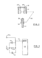
- the earth edge connector that is, connector 14
- the earth edge connector has a portion 29 which projects from the connector into the area of board 1 which would normally be occupied by an edge connector adjacent connector 14.
- the arrangement is such that as board 1 is slotted into the connector socket, projection 29 is momentarily engaged by the associated contact of connector contact pair 27. Similarly, when board 1 is removed from the connector socket, projection 29 is again momentarily engaged by this connector contact.
- the broken line 30 indicates the contact point of the edge connectors on board 1 and the contacts in the socket when the board is fully inserted into the socket.
- FIG. 3 is a highly simplified diagram showing the connection between contact 27a ( Figure 2) and a microprocessor 40.
- the microprocessor in this case, is assumed to be on which is responsive to the lowering of a voltage on a NOT RESET input line 41 followed by a return to a high condition to switch to its reset state.
- the voltage on line 41 is substantially.that of the supply voltage at terminal 42, as there is substantially no voltage drop across resistor 43.
- contact 27a is earthed by projection 29 ( Figure 2)
- the potential of line 41 drops to earth, and when it subsequently leaves the projection, the input rises back up to the supply level.
- the reset pulse is lengthened by the RC characteristics of resistor 43 and capacitor 45.
- Diode 44 provides a path to quickly discharge the capacitor when the system is powered down.
- contact 27a may be coupled to a RESET input of a microprocessor through an invert circuit.
- contact pad 14 may be the power supply pad for the cartridge so that, upon insertion or removal of the cartridge, a pulse at the supply voltage is produced on line 32 for a RESET input of the microprocessor.
- the ROM cartridge provides program control data for a microcomputer system. Without some form of reset control when the cartridge is entered or withdrawn, noise signals generated thereby can cause significant problems. As this noise may be interpreted as program data, the computer may well attempt to execute the phantom instructions produced by the noise signals. These will at least produce error indications requiring action by the operator. The computer can, under some conditions produced by the phantom instructions, be forced into a 'hang' condition in which it waits for a further, non-existent instruction without the ability to return to its main control routine. In such a situation it may be impossible to reset the computer, and the only possible action is to switch it off completely and then switch on again.
- this power on sequence may include a check of the system, a keyboard check, an operating system load operation and peripheral device (e.g. diskette and hard disk) load operations. These operations may take a minute or more in some systems.
- the reset system disclosed herein is simple, cheap to produce and effective. It will be noted that the reset signal is produced immediately after initial contact between the connector pads on the cartridge and the contacts on the cartridge holder. By the time the system has been reset, the contacts and pads are in wiping contact so that as soon as the cartridge is pushed to its home position further operations can continue. Similarly, when a cartridge is withdrawn, the reset signal occurs as the cartridge is finally exiting from the connector socket, so the system is again reset for the start of further operations.
- each cartridge includes a printed circuit board carrying along one edge a plurality of parallel edge connectors for connection of the cartridge to corresponding contacts of a socket in the micro- computer, in which one of the edge connectors includes a portion extending into the area on the board which would normally be occupied by an adjacent connector, the extending portion being configured to transiently engage a corresponding first contact of the socket upon insertion of the board into, or withdrawal of the board from, the socket, whereby a fixed potential applied by the microcomputer to a second socket contact corresponding to the main portion of said one edge connector is transiently transferred through the extending portion to the first contact to provide a reset signal thereon to reset the microprocessor of the microcomputer on insertion or withdrawal of the cartridge.
- the extending portion is of similar width to said main portion and extends normal to the main portion into said area on the board, forming an L-shaped conductive area with said extending portion passing adjacent said one edge of the board into said area on the board.
- the extended connector can be the ground connector of the board, said second contact being connected to the ground of the microcomputer, and a predetermined potential on said second contact is reduced to ground potential on said transient engagement with the extending portion of the extended edge connector.
- Each contact in the socket includes a portion curved towards the board to engage a portion of its associated edge connector remote from the edge of the board when the board is fully in position in the socket, the configuration of said extending portion being such that when the board is fully inserted into the socket, the curved portion of the first contact is out of engagement with the extending portion.
- a cartridge socket having a first contact connected to a fixed potential and a second contact, adjacent the first contact, coupled to a reset input of a microprocessor in the system, and, in each cartridge, a printed circuit board having a plurality of edge connectors corresponding to the contacts in the socket, one of the edge connectors, corresponding to said first contact in the socket, having a projection extending into the area which would normally be occupied by an edge connector corresponding to said second contact and configured to transiently engage the second contact as the cartridge is inserted into or withdrawn from the socket.
Landscapes
- Engineering & Computer Science (AREA)
- Theoretical Computer Science (AREA)
- Physics & Mathematics (AREA)
- General Engineering & Computer Science (AREA)
- General Physics & Mathematics (AREA)
- Microelectronics & Electronic Packaging (AREA)
- Human Computer Interaction (AREA)
- Debugging And Monitoring (AREA)
- Details Of Connecting Devices For Male And Female Coupling (AREA)
- Multi Processors (AREA)
- Coupling Device And Connection With Printed Circuit (AREA)
- Microcomputers (AREA)
- Hardware Redundancy (AREA)
- Photoreceptors In Electrophotography (AREA)
- Communication Control (AREA)
Priority Applications (1)
| Application Number | Priority Date | Filing Date | Title |
|---|---|---|---|
| AT84107802T ATE31985T1 (de) | 1983-08-12 | 1984-07-05 | Datenverarbeitungsanordnung, die eine automatische ruecksetzeinrichtung enthaelt. |
Applications Claiming Priority (2)
| Application Number | Priority Date | Filing Date | Title |
|---|---|---|---|
| US06/522,894 US4632398A (en) | 1983-08-12 | 1983-08-12 | Reset system for microcomputer using program cartridges |
| US522894 | 1983-08-12 |
Publications (3)
| Publication Number | Publication Date |
|---|---|
| EP0134967A2 true EP0134967A2 (fr) | 1985-03-27 |
| EP0134967A3 EP0134967A3 (en) | 1985-05-29 |
| EP0134967B1 EP0134967B1 (fr) | 1988-01-13 |
Family
ID=24082815
Family Applications (1)
| Application Number | Title | Priority Date | Filing Date |
|---|---|---|---|
| EP84107802A Expired EP0134967B1 (fr) | 1983-08-12 | 1984-07-05 | Système de traitement de données comprenant un appareil de mise à zéro automatique |
Country Status (14)
| Country | Link |
|---|---|
| US (1) | US4632398A (fr) |
| EP (1) | EP0134967B1 (fr) |
| JP (1) | JPS60184135U (fr) |
| KR (1) | KR890002466B1 (fr) |
| AT (1) | ATE31985T1 (fr) |
| BR (1) | BR8403986A (fr) |
| CA (1) | CA1200861A (fr) |
| DE (1) | DE3468757D1 (fr) |
| ES (1) | ES8604700A1 (fr) |
| GB (1) | GB2144890A (fr) |
| HK (1) | HK99389A (fr) |
| MX (1) | MX155973A (fr) |
| SG (1) | SG62289G (fr) |
| ZA (1) | ZA845251B (fr) |
Cited By (5)
| Publication number | Priority date | Publication date | Assignee | Title |
|---|---|---|---|---|
| WO1988009573A1 (fr) * | 1987-05-19 | 1988-12-01 | Cambridge Computer Limited | Ameliorations apportees a des micro-ordinateurs |
| EP0317081A3 (fr) * | 1987-11-18 | 1990-07-11 | Hewlett-Packard Company | Interupteur de réarmement pour circuit imprimé |
| EP0370493A3 (en) * | 1988-11-21 | 1990-10-31 | Oki Electric Industry Co., Ltd. | Electric circuit device with an improved cartridge connection circuit |
| EP0551826A1 (fr) * | 1992-01-15 | 1993-07-21 | Molex Incorporated | Connecteur de bordure pour circuit imprimé |
| US12215505B2 (en) | 2009-09-04 | 2025-02-04 | Välinge Innovation AB | Resilient floor |
Families Citing this family (5)
| Publication number | Priority date | Publication date | Assignee | Title |
|---|---|---|---|---|
| DE3603807C1 (de) * | 1986-02-07 | 1987-07-30 | Triumph Adler Ag | Verfahren und Schaltungsanordnung zum Schutz von Schreib- oder aehnlichen Bueromaschinen vor den Folgen von elektrostatischen Entladungen |
| JPH0796321B2 (ja) * | 1986-04-17 | 1995-10-18 | キヤノン株式会社 | 出力装置 |
| KR930012128B1 (ko) * | 1989-08-28 | 1993-12-24 | 가부시기가이샤 도시바 | 재개기능을 가진 컴퓨터 유니트 |
| JP4734484B2 (ja) * | 2000-10-19 | 2011-07-27 | 新世代株式会社 | 情報処理装置およびメモリカートリッジシステム |
| KR102792334B1 (ko) | 2019-09-03 | 2025-04-08 | 삼성전자주식회사 | 소켓을 이용한 전원 제어 방법 및 이를 지원하는 전자 장치 |
Family Cites Families (5)
| Publication number | Priority date | Publication date | Assignee | Title |
|---|---|---|---|---|
| US4017696A (en) * | 1975-12-31 | 1977-04-12 | Bell Telephone Laboratories, Incorporated | Initializing circuit |
| US4471465A (en) * | 1979-01-08 | 1984-09-11 | Atari, Inc. | Video display system with multicolor graphics selection |
| US4368515A (en) * | 1981-05-07 | 1983-01-11 | Atari, Inc. | Bank switchable memory system |
| US4462076A (en) * | 1982-06-04 | 1984-07-24 | Smith Engineering | Video game cartridge recognition and security system |
| US4480835A (en) * | 1983-03-02 | 1984-11-06 | Williams Theodore R | Cartridge adapter for programmable video games |
-
1983
- 1983-08-12 US US06/522,894 patent/US4632398A/en not_active Expired - Fee Related
-
1984
- 1984-05-16 JP JP1984070473U patent/JPS60184135U/ja active Granted
- 1984-07-03 GB GB08416921A patent/GB2144890A/en not_active Withdrawn
- 1984-07-05 DE DE8484107802T patent/DE3468757D1/de not_active Expired
- 1984-07-05 AT AT84107802T patent/ATE31985T1/de active
- 1984-07-05 EP EP84107802A patent/EP0134967B1/fr not_active Expired
- 1984-07-06 ZA ZA845251A patent/ZA845251B/xx unknown
- 1984-07-06 CA CA000458354A patent/CA1200861A/fr not_active Expired
- 1984-07-12 KR KR1019840004077A patent/KR890002466B1/ko not_active Expired
- 1984-08-09 MX MX202314A patent/MX155973A/es unknown
- 1984-08-09 BR BR8403986A patent/BR8403986A/pt not_active IP Right Cessation
- 1984-08-10 ES ES535058A patent/ES8604700A1/es not_active Expired
-
1989
- 1989-09-09 SG SG622/89A patent/SG62289G/en unknown
- 1989-12-14 HK HK993/89A patent/HK99389A/en unknown
Cited By (7)
| Publication number | Priority date | Publication date | Assignee | Title |
|---|---|---|---|---|
| WO1988009573A1 (fr) * | 1987-05-19 | 1988-12-01 | Cambridge Computer Limited | Ameliorations apportees a des micro-ordinateurs |
| GB2226167A (en) * | 1987-05-19 | 1990-06-20 | Cambridge Computer | Improvements in or relating to microcomputers |
| GB2226167B (en) * | 1987-05-19 | 1991-08-07 | Cambridge Computer | Improvements in or relating to microcomputers |
| EP0317081A3 (fr) * | 1987-11-18 | 1990-07-11 | Hewlett-Packard Company | Interupteur de réarmement pour circuit imprimé |
| EP0370493A3 (en) * | 1988-11-21 | 1990-10-31 | Oki Electric Industry Co., Ltd. | Electric circuit device with an improved cartridge connection circuit |
| EP0551826A1 (fr) * | 1992-01-15 | 1993-07-21 | Molex Incorporated | Connecteur de bordure pour circuit imprimé |
| US12215505B2 (en) | 2009-09-04 | 2025-02-04 | Välinge Innovation AB | Resilient floor |
Also Published As
| Publication number | Publication date |
|---|---|
| BR8403986A (pt) | 1985-07-09 |
| ATE31985T1 (de) | 1988-01-15 |
| KR850002612A (ko) | 1985-05-15 |
| ZA845251B (en) | 1985-03-27 |
| EP0134967A3 (en) | 1985-05-29 |
| MX155973A (es) | 1988-06-03 |
| ES535058A0 (es) | 1986-02-01 |
| US4632398A (en) | 1986-12-30 |
| HK99389A (en) | 1989-12-22 |
| SG62289G (en) | 1990-01-26 |
| JPS60184135U (ja) | 1985-12-06 |
| KR890002466B1 (ko) | 1989-07-10 |
| DE3468757D1 (en) | 1988-02-18 |
| ES8604700A1 (es) | 1986-02-01 |
| GB8416921D0 (en) | 1984-08-08 |
| CA1200861A (fr) | 1986-02-18 |
| JPH021613Y2 (fr) | 1990-01-16 |
| GB2144890A (en) | 1985-03-13 |
| EP0134967B1 (fr) | 1988-01-13 |
Similar Documents
| Publication | Publication Date | Title |
|---|---|---|
| US5164880A (en) | Electrostatic discharge protection device for a printed circuit board | |
| US7068517B2 (en) | Low height USB interface connecting device and a memory storage apparatus thereof | |
| EP0134967B1 (fr) | Système de traitement de données comprenant un appareil de mise à zéro automatique | |
| EP0233649B1 (fr) | Carte à mémoire à circuit intégré incorporé | |
| US3938068A (en) | Electrical plug and outlet unit | |
| KR200356231Y1 (ko) | 멀티-인-원 커넥터 구조 | |
| MY103199A (en) | Slab-like jack module | |
| GB2222731A (en) | Connecting mechanism for memory card or other portable storage apparatus | |
| US4203638A (en) | Electrical receptacle and grounding strip therefor | |
| KR19980703279A (ko) | 스마트 카드 판독 장치용 판독기 프레임 | |
| RU97117365A (ru) | Рамка считывания для устройства считывания карточки с микросхемой | |
| US4767341A (en) | Printed circuit card reset switch | |
| US4755902A (en) | Electronic apparatus with detachable member arranged to detect erroneous mounting of the detachable member | |
| RU97117346A (ru) | Разъем для устройства считывания карточки со встроенной микросхемой | |
| EP0066109A1 (fr) | Module compteur enfichable | |
| JPS59165386A (ja) | 多極コネクタ | |
| CN208461865U (zh) | 电子装置、导通卡以及导通触发系统 | |
| JPH05342433A (ja) | データ処理装置 | |
| US6231351B1 (en) | Electrical connector | |
| US7005877B2 (en) | Burn-in adapter | |
| EP0472420A2 (fr) | Structure de connexion pour cartes à circuit intégré | |
| JPH04101373A (ja) | コネクタ誤挿入防止回路 | |
| JPS5843798Y2 (ja) | 電子制御盤のプリント基板装着装置 | |
| JP2580908B2 (ja) | 制御装置 | |
| JPH0245971Y2 (fr) |
Legal Events
| Date | Code | Title | Description |
|---|---|---|---|
| PUAI | Public reference made under article 153(3) epc to a published international application that has entered the european phase |
Free format text: ORIGINAL CODE: 0009012 |
|
| PUAL | Search report despatched |
Free format text: ORIGINAL CODE: 0009013 |
|
| 17P | Request for examination filed |
Effective date: 19841123 |
|
| AK | Designated contracting states |
Designated state(s): AT BE CH DE FR GB IT LI NL SE |
|
| AK | Designated contracting states |
Designated state(s): AT BE CH DE FR GB IT LI NL SE |
|
| 17Q | First examination report despatched |
Effective date: 19860711 |
|
| GRAA | (expected) grant |
Free format text: ORIGINAL CODE: 0009210 |
|
| AK | Designated contracting states |
Kind code of ref document: B1 Designated state(s): AT BE CH DE FR GB IT LI NL SE |
|
| REF | Corresponds to: |
Ref document number: 31985 Country of ref document: AT Date of ref document: 19880115 Kind code of ref document: T |
|
| REF | Corresponds to: |
Ref document number: 3468757 Country of ref document: DE Date of ref document: 19880218 |
|
| ET | Fr: translation filed | ||
| ITF | It: translation for a ep patent filed | ||
| PLBE | No opposition filed within time limit |
Free format text: ORIGINAL CODE: 0009261 |
|
| STAA | Information on the status of an ep patent application or granted ep patent |
Free format text: STATUS: NO OPPOSITION FILED WITHIN TIME LIMIT |
|
| 26N | No opposition filed | ||
| ITTA | It: last paid annual fee | ||
| PGFP | Annual fee paid to national office [announced via postgrant information from national office to epo] |
Ref country code: CH Payment date: 19931012 Year of fee payment: 10 |
|
| PG25 | Lapsed in a contracting state [announced via postgrant information from national office to epo] |
Ref country code: LI Effective date: 19940731 Ref country code: CH Effective date: 19940731 |
|
| EAL | Se: european patent in force in sweden |
Ref document number: 84107802.5 |
|
| REG | Reference to a national code |
Ref country code: CH Ref legal event code: PL |
|
| PGFP | Annual fee paid to national office [announced via postgrant information from national office to epo] |
Ref country code: AT Payment date: 19950530 Year of fee payment: 12 |
|
| PGFP | Annual fee paid to national office [announced via postgrant information from national office to epo] |
Ref country code: GB Payment date: 19950622 Year of fee payment: 12 |
|
| PGFP | Annual fee paid to national office [announced via postgrant information from national office to epo] |
Ref country code: FR Payment date: 19950704 Year of fee payment: 12 |
|
| PGFP | Annual fee paid to national office [announced via postgrant information from national office to epo] |
Ref country code: BE Payment date: 19950707 Year of fee payment: 12 |
|
| PGFP | Annual fee paid to national office [announced via postgrant information from national office to epo] |
Ref country code: SE Payment date: 19950717 Year of fee payment: 12 |
|
| PGFP | Annual fee paid to national office [announced via postgrant information from national office to epo] |
Ref country code: DE Payment date: 19950720 Year of fee payment: 12 |
|
| PGFP | Annual fee paid to national office [announced via postgrant information from national office to epo] |
Ref country code: NL Payment date: 19950725 Year of fee payment: 12 |
|
| PG25 | Lapsed in a contracting state [announced via postgrant information from national office to epo] |
Ref country code: GB Effective date: 19960705 Ref country code: AT Effective date: 19960705 |
|
| PG25 | Lapsed in a contracting state [announced via postgrant information from national office to epo] |
Ref country code: SE Effective date: 19960706 |
|
| PG25 | Lapsed in a contracting state [announced via postgrant information from national office to epo] |
Ref country code: BE Effective date: 19960731 |
|
| BERE | Be: lapsed |
Owner name: INTERNATIONAL BUSINESS MACHINES CORP. Effective date: 19960731 |
|
| PG25 | Lapsed in a contracting state [announced via postgrant information from national office to epo] |
Ref country code: NL Effective date: 19970201 |
|
| GBPC | Gb: european patent ceased through non-payment of renewal fee |
Effective date: 19960705 |
|
| PG25 | Lapsed in a contracting state [announced via postgrant information from national office to epo] |
Ref country code: FR Effective date: 19970328 |
|
| NLV4 | Nl: lapsed or anulled due to non-payment of the annual fee |
Effective date: 19970201 |
|
| PG25 | Lapsed in a contracting state [announced via postgrant information from national office to epo] |
Ref country code: DE Effective date: 19970402 |
|
| EUG | Se: european patent has lapsed |
Ref document number: 84107802.5 |
|
| REG | Reference to a national code |
Ref country code: FR Ref legal event code: ST |