EP0135494A2 - Kombination Photodetektor Aufstellung/Maske Positionierungsverfahren - Google Patents
Kombination Photodetektor Aufstellung/Maske Positionierungsverfahren Download PDFInfo
- Publication number
- EP0135494A2 EP0135494A2 EP84890141A EP84890141A EP0135494A2 EP 0135494 A2 EP0135494 A2 EP 0135494A2 EP 84890141 A EP84890141 A EP 84890141A EP 84890141 A EP84890141 A EP 84890141A EP 0135494 A2 EP0135494 A2 EP 0135494A2
- Authority
- EP
- European Patent Office
- Prior art keywords
- piece
- array
- illumination
- area
- photosensitive
- Prior art date
- Legal status (The legal status is an assumption and is not a legal conclusion. Google has not performed a legal analysis and makes no representation as to the accuracy of the status listed.)
- Granted
Links
Images






Classifications
-
- B—PERFORMING OPERATIONS; TRANSPORTING
- B25—HAND TOOLS; PORTABLE POWER-DRIVEN TOOLS; MANIPULATORS
- B25J—MANIPULATORS; CHAMBERS PROVIDED WITH MANIPULATION DEVICES
- B25J9/00—Program-controlled manipulators
- B25J9/16—Program controls
- B25J9/1694—Program controls characterised by use of sensors other than normal servo-feedback from position, speed or acceleration sensors, perception control, multi-sensor controlled systems, sensor fusion
- B25J9/1697—Vision controlled systems
Definitions
- the present invention relates to object positioning apparatus, in general, and to apparatus for. automatically positioning a piece-part in a predetermined orientation for subsequent assembly into a product, in particular.
- Industrial robots are capable of repetitively performing various mechanical tasks with a high degree of speed and accuracy in response to * a set of programmed instructions such as the task of moving a piece-part or workpiece from one position to another as part of a product assembly process.
- Present techniques for positioning a piece-part prior to movement of same by an industrial robot employ the use of such components as a conventional X,Y,-6- piece-part orienting turntable in conjunction with a piece-part image sensing TV camera and a digital computer in which the physical characteristics of a particular piece-part are stored for subsequent piece-part recognition and orientation purposes. While these techniques are effective for such purposes, computers and TV cameras are relatively expensive items and a computer requires the services of a relatively high-cost computer pro- g rammer in order to describe the physical characteristics of each individual piece-part in sufficiently detailed computer language so as to be unambiguously recognized by the piece-part positioning system. In addition, while computerized piece-part positioning systems are able to position piece parts at an acceptable rate of speed for many product assembly applications, their ability to position relatively complex shaped piece-parts at the
- the present invention relates to object positioning apparatus, in general, and to apparatus for. automatically positioning a piece-part in a predetermined orientation for subsequent assembly into a product, in particular.
- Industrial robots are capable of repetitively performing various mechanical tasks with a high degree of speed and accuracy in response to ' a set of programmed instructions such as the task of moving a piece-part or workpiece from one position to another as part of a product assembly process.
- Present techniques for positioning a piece-part prior to movement of same by an industrial robot employ the use of such components as a conventional X,Y, ' 6- piece-part orienting turntable in conjunction with a piece-part image sensing TV camera and a digital computer in which the physical characteristics of a particular piece-part are stored for subsequent piece-part recognition and orientation purposes. While these techniques are effective for such purposes, computers and TV cameras are relatively expensive items and a computer requires the services of a relatively high-cost computer programmer in order to describe the physical characteristics of each individual piece-part in sufficiently detailed computer language so as to be unambiguously recognized by the piece-part positioning system.
- the primary object of the present invention therefore is to provide low-cost apparatus for rapidly placing randomly oriented, relatively complex shaped objects in a predetermined position and orientation.
- Another object of the present invention is to provide means for substantially reducing the time required to describe the characteristics of an object in machine recognizable form for automated object positioning purposes.
- a further object of the present invention is to provide means for describing machine recognizable object characteristics that readily allows substitution of the machine recognizable description of one type of object to be positioned for that of another.
- a simplified object positioning system is disclosed that is capable of rapidly moving relatively complex objects to a desired orientation within a predetermined area or location.
- the system includes a movable support surface coupled to drive means capable of moving said surface in any direction along a given plane and/or about an axis perpendicular to said given plane in response to drive means positioning signals.
- the system also includes part-position sensing means comprising a generally planar set of photosensitive elements electrically divided into a plurality of groups and positioned to sense light from a light source that backlights an object to be positioned located on said movable surface for the purpose of determining any deviation of the shadow of said backlighted object falling on said photosensitive set from that of a slightly enlarged light attenuating image of said object forming a part of or positioned adjacent said photosensitive element set, and for generating an electrical signal indicative of such. deviation in order to cause said drive means to position the shadow and indirectly the object within the outline or silhouette of said object image in response to object position deviation signals generated by said photosensitive element set.
- Fig. 1 of the drawings a system diagram of object positioning apparatus 12 incorporating a preferred embodiment of the present invention, is depicted.
- the major components associated with apparatus 12 are mechanical vibrator 14 for supplying and delivering the part to be positioned, X,Y,0• table 16 for moving the part in any direction within a particular plane and/or about an axis at right angles to said plane to a predetermined area or location, a pair of electrically activated actuators with one actuator 18 for pushing the part onto table 16 and another actuator 20 for pushing rejected parts off said table into receptacle 22, vision module 24 for sensing piece-part position relative to said predetermined area and generating signals representative of said relative position, industrial robot 26 that places properly positioned piece-parts on conveyor belt 28 and control unit 30 that controls the operation of these major apparatus 12 components.
- mechanical vibrator 14 for supplying and delivering the part to be positioned
- X,Y,0• table 16 for moving the part in any direction within a particular plane and/or about an axis at right angles to said plane
- Mechanical vibrator 14 moves piece-parts from its piece-part containing hopper 32 down chute 34 and onto receiving table 36 when activated by control unit 30 through path 38, part movement that is compatible with a predetermined sequence of events to be described below in detail.
- Piece-part presence on receiving table 36 is detected by conventional object sensing device 40 and a signal indicating such presence is routed to control unit 30 through path 42.
- the signal flow block diagram of Fig. 2 shows the overall sequence of operation of posi- . tioning apparatus 12.
- actuator 18 pushes a single piece-part that has been sensed by sensing device 40 onto backlighted surface 46 of table 16 for part positioning/orienting purposes.
- the retraction of actuator 18 to its initial or home position is the signal that initiates part positioning and starts a timer that will cause the piece-part to be rejected if not properly positioned within a maximum of 3 seconds.
- the initial or actual position of this piece-part on surface 46 is sensed by vision module 24 (described in detail below) and its position is compared with the desired position described and/or defined within said module 24.
- Module 24 subsequently generates piece-part position error signals that are routed to table 16 through control unit 30 and paths 48 and 50 for X,Y,0• table 16 positioning purposes. These error signals are decoded by decoder units within control unit 30. Upon receipt of these error signals, table 16 moves its surface 46 together with the piece-part located thereon along the plane of said surface 46 and/or about an axis that is perpendicular to surface 46 until the piece-part is positioned to the desired position as determined by vision module 24 and the position error signals are reduced to zero, which results in the termination of said surface 46 movement and the piece-part located thereon.
- actuator 20 pushes the piece-part into receptacle 22 in response to a reject signal from control unit 30 through path 52.
- the piece-part is picked up from what is now a fairly well defined position by industrial robot 26 in response to a piece-part position signal from vision module 24 to control unit 30 through path 48 and preprogrammed industrial robot positioning signals from control unit 30 to robot 26 through path 53 and placed on conveyor belt 28 in a similarly well-defined position by said robot 26.
- positioning apparatus 12 such as mechanical vibrator 14, actuators 18 and 20 and industrial robot 26 are fairly conventional devices while others such as vision module 24, control unit 30 and portions of X,Y,0 ⁇ table 16 are not. It is primarily, though not exclusively, the design and interaction of the latter threecomponents that embodies the present inventive concept, and these components and their relationship to one another will now be described in detail.
- Vision module 24 senses the position of an object or a complex shaped product piece-part such as part 54 in drawing F ig. 3, relative to a predetermined area or position whose contours are fairly well defined within said module 24 and generates an electrical signal(s) representative of said relative position.
- Enlarged top and side views of part 54 are shown in Figs. 4A and 4B, respectively.
- Module 24 includes housing 56 which is mounted in a fixed position above surface 46 of part-moving table 16. One end of housing 56 has three adjacent part-position sensing layers enclosing one end thereof.
- Innermost layer 58 is a glass light-diffusing layer whose function is to uniformly distribute light falling on one side thereof.
- Middle layer 60 is a slightly enlarged transparency of the positive image or silhouette of the part to be positioned.
- Photosensitive or outermost layer 62 includes a set or array of photosensitive elements 64 that, in conjunction with image layer 60 and a shadow of said piece-part 54, generates an electrical signal representative of piece-part 54 position relative to the piece-part image on said image layer 60 in a manner to be described in detail below.
- Housing 56 of module 24 also includes image-forming, light-focusing lens 66 at the end of housing 56 opposite from that of end layers 58, 60 and 62.
- Light source 68 within the upper or movable portion of table 16, (Fig. 1) lights the transluscent top surface 46 of said table 16 while at the same backlighting complex product piece-part 54 positioned thereon.
- image or shadow 70 of backlighted part 54 is formed adjacent light diffusing layer 58 by lens 66.
- the part position signals produced by the photosensitive elements of photosensitive array 64 are generated whenever image 70 of part 54 and the slightly enlarged silhouette of said part 54 in layer 60 are out of registration or alignment with one another. Following are the specific details of how the part position signals are generated by such misalignment.
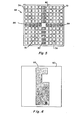
- Fig. 5 which is an enlarged bottom view of photosensitive array 64 shown in drawing Fig. 3, said array 64 consists of 120, 9.5 mm square, uniformly distributed, photosensitive elements that are electrically subdivided into eight groups for the purpose of generating eight separate light-responsive signals to be employed for part positioning purposes. If necessary, a different number of groups having a different element size may be chosen to suit a particular part positioning task.
- These conventional photosensitive elements generate an electrical signal whenever they are illuminatedby a suitable light source of sufficient intensity.
- Photosensitive array 64 is subdivided into 4 quadrant groups QI (72), QII (74), QIII (76) and QIV (78) with each of said quadrant groups containing a total of 25 photosensitive elements.
- array 64 is also subdivided into 4 linear or directional groups QN (80), QS (82), QE (84) and QW (86) with each of said directional groups containing a total of 5 photosensitive elements.
- FIG. 6 a bottom view of image or mask layer 60 that cooperates with said array 64 for object or part-positioning purposes is shown in drawing Fig. 6.
- Mask layer 60 consists of a transparency of slightly enlarged positive image 88 of part 54 (Figs. 3, 4A and 4B) which is the part to be positioned by automatic piece-part positioning apparatus 12 (Fig. 1).
- This slightly enlarged image 88 is relatively opaque, is produced by standard or conventional photographic techniques for each different type of part to be positioned and is directly related to the predetermined area or location to which the piece-part is to be positioned.
- positive image 88 overlies portions of photosensitive array 64 in the manner shown in drawing Fig. 7.
- the shadow or actual image of a backlighted piece-part such as the shadow of part 54 in drawing F ig. 3 that is focussed on mask layer 60 by vision module lens 66, will fall completely within said positive piece-part image 88 which is the condition that will cause said apparatus 12 to terminate part 54 movement.
- the outline of the shadow or image of piece-part 54 is indicated by line 90 in drawing Fig. 7.
- Fig. 8A shows a signal flow block diagram of the control system portion of the object positioning system of the present invention that relies on the above-mentioned photosensitive array 64, mask layer 60 and object shadow interraction for object or part-positioning purposes.
- quadrants QI (72), QII (74), QIII (76) and QIV (78) of photosensitive array 64 (Fig. 5) each contain a total of 25 parallel-connected photosensitive elements.
- Fig. 8A also shows linear or directional photosensitive element groups QN (80), QS (82), QE (84) and QW (86) of photosensitive array 64 with each of said directional groups containing a total of 5 parallel-connected photosensitive elements.
- FIG. 8B A schematic diagram of one of the parallel-connected, 5 photosensitive element containing linear directional groups connected in electrical parallel is shown in drawing Fig. 8B. All of the photosensitive element groups shown in drawing Fig. 8A are the equivalent of photosensitive element groups with the corresponding reference numerals shown in drawing Fig. 5.
- Each of the above-described photosensitive element groups has its output connected to a variable output amplifier
- each variable amplifier is, in turn, connected to a comparator
- decoders 96, 98 and 100 are routed to table control unit 102 and then to X,Y, ⁇ table 16 through a set of enabling gates 104, to control part-positioning by the rectilinear and/or rotational movement of surface 46 of table 16.
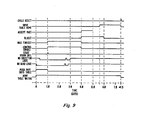
- timing and control electronics 106 in the control system of Fig. 8A controls the part positioning system of the present invention in accordance with the typical time line shown in drawing Fig. 9. Signals representative of the condition of various components of the part-positioning system are routed to timing and control electronics 106 so that part-positioning in accordance with said Fig. 9 timeline can be provided.
- Part of the part-positioning control scheme requires that certain movable components return to an initial or predetermined home position for each part positioning cycle.
- X Home and Y Home signals 108 and 110 respectively, indicate the positioning of surface 46 of the upper or movable portion of table 16 to its initial position.
- Push Mechanism Home signal 112 and the Reject Mechanism Home signal l14 indicate when part introducing actuator 18 and part rejecting actuator 20, respectively, have returned to their initial positions.
- Accept Mechanism Home signal 116 indicates the return of industrial robot 26 to its predetermined initial position and the input to timing the control electronics from decoder 118 indicates no output from any of the comparators 94 which signifies that the part to be positioned has been moved or positioned to the above-mentioned predetermined location or area.
- Initiate Push Mechanism signal 120 causes actuator 18 to push a part from receiving table 36 to surface 46 of table 16
- Initiate Reject Mechanism 122 causes actuator 20 to push a rejected part into receptacle 22
- Accept Part signal 124 causes industrial robot 26 to move a properly positioned piece-part from surface 46 of table 16 to conveyor 28 in what would then be a relatively well defined orientation of the piece-part.
- Timing and control electronics 106 also transmits a table 16 control unit enabling signal to enabling gates 104,through path 126, once each part-positioning cycle.
- the control system of Fig. 8A is adjusted and/or calibrated for each different type of object or piece-part for automatic piece-part orientation in the following manner.
- mask 60 overlies photosensitive array 64 as in Fig. 7, and said array 64 and mask 60 are positioned in vision module 24 as shown in Fig. 3 and there are no parts or objects on surface 46 of table 16, some of the light rays from light source 68 of said table 16 that would otherwise be focused on the photosensitive element groups of array 64 by lens 66 are blocked or are prevented from falling on portions of said array 64 by enlarged positive image portion 88 of said mask 60.
- the shape and size of image portion 88 and therefore the extent of the blockage of light from array 64 is a function of the shape of the top or plan view of the piece part to be positioned which varies with each type of part and the selected orientation for each such part.
- the effect of the unequal illumination falling on the different photosensitive array 64 groups is neutralized for each different type of part by the amplifiers 92 connected to the output of said photosensitive array groups.
- each of the amplifiers 92 is then adjusted to -10.0 v. In this condition, there will be no output from any of the comparators 94.
- Calibration switch 128 is then placed in its run position. In this state, a comparator in the group of comparators 94 will generate an output whenever the magnitude of its associated amplifier in group of amplifiers 92 becomes less negative than -9.8 v. A reduction in the voltage output of amplifier 92 occurs whenever a part to be positioned is moved onto surface 46 of table 16 as part of the piece-part positioning process such that the level of illumination falling on photosensitive array 64 is reduced below that falling on said array during the calibration process.
- Part-positioning signals resulting from a reduction in the illumination falling on photosensitive element groups 72, 74, 76, 78, 80, 82, 84 and/or 86 cause corresponding outputs from comparators 94 that are applied to decoders 96, 98, 100 and 118 where they are decoded in accordance with the following table for the control or movement of the upper portion of part-positioning table 16 and the part located thereon.
- Linear directions ⁇ X and f Y are directions of a standard rectangular coordinate system in a plane containing photosensitive array 64 and rotational directions ⁇ are directions of a standard polar coordinate system that consist of rotational movement about an axis perpendicular to said plane of array 64.
- Fig. 10 is a logic diagram schematic that implements the above signal-decoding table for the control of part-positioning table 16.
- object positioning apparatus 12 for the purpose of placing an object or piece-part in the relatively well-defined position and orientation.
- a slightly enlarged positive image or mask layer 60 of the part to be positioned has been prepared and properly positioned within vision module 24 (Fig. 3).
- the control system positioning apparatus 12 has been calibrated, that parts are present in hopper 32, that a part has been detected on receiving table 36 by object sensing device 40 and that all of the movable mechanisms are at their initial or home positions.
- the part-positioning sequence begins when timing and control electronics 106 enables gates 104 and generates Initiate Push Mechanism signal 120 which causes actuator 18'to move a piece-part onto backlighted surface 46 of table 16 and then return to its home position.
- Initiate Push Mechanism signal 120 causes actuator 18'to move a piece-part onto backlighted surface 46 of table 16 and then return to its home position.
- This reduction in illumination will cause the magnitude of the voltage level output of one or more of the photosensitive groups to drop which, ,in turn, causes the input to one or more of the comparators 94 to become less negative than -9.8 V thereby causing one or more of the comparators 94 to generate a part-positioning output signal that is routed to decoders 96, 98, 100 and/or 118 where it is decoded in accordance with the above table and the corresponding logic diagram of Fig. 10.
- the decoded signal is routed through one or more of the enabling gates 104 to table control unit 102 for table 16 movement and therefore piece-part positioning purposes. When the piece-part has been moved by table 16 such that its shadow or actual image 90 falls completely within its enlarged image 88 (Fig.
- Decoder 118 informs timing and control electronics unit 106 when a piece-part has been positioned to a predetermined location (within enlarged positive image 88 of Fig. 7) and then timing and control electronics unit 106 generates Accept Part signal 124 causing industrial robot 26 to place the just-positioned piece-part on conveyer belt 28 in what would then be a fairly well defined piece-part orientation.
- a cycle reset pulse Fig. 9
Landscapes
- Engineering & Computer Science (AREA)
- Robotics (AREA)
- Mechanical Engineering (AREA)
- Length Measuring Devices By Optical Means (AREA)
- Exposure And Positioning Against Photoresist Photosensitive Materials (AREA)
- Exposure Of Semiconductors, Excluding Electron Or Ion Beam Exposure (AREA)
- Manipulator (AREA)
- Image Processing (AREA)
- Image Analysis (AREA)
- Optical Head (AREA)
- Control Of Position Or Direction (AREA)
- Supply And Installment Of Electrical Components (AREA)
- Image Input (AREA)
Priority Applications (1)
| Application Number | Priority Date | Filing Date | Title |
|---|---|---|---|
| AT84890141T ATE52627T1 (de) | 1983-07-28 | 1984-07-27 | Kombination photodetektor aufstellung/maske positionierungsverfahren. |
Applications Claiming Priority (2)
| Application Number | Priority Date | Filing Date | Title |
|---|---|---|---|
| US518053 | 1983-07-28 | ||
| US06/518,053 US4575637A (en) | 1983-07-28 | 1983-07-28 | Part positioning system employing a mask and photodetector array |
Publications (3)
| Publication Number | Publication Date |
|---|---|
| EP0135494A2 true EP0135494A2 (de) | 1985-03-27 |
| EP0135494A3 EP0135494A3 (en) | 1986-12-17 |
| EP0135494B1 EP0135494B1 (de) | 1990-05-09 |
Family
ID=24062340
Family Applications (1)
| Application Number | Title | Priority Date | Filing Date |
|---|---|---|---|
| EP84890141A Expired - Lifetime EP0135494B1 (de) | 1983-07-28 | 1984-07-27 | Kombination Photodetektor Aufstellung/Maske Positionierungsverfahren |
Country Status (6)
| Country | Link |
|---|---|
| US (1) | US4575637A (de) |
| EP (1) | EP0135494B1 (de) |
| JP (2) | JPS6084679A (de) |
| AT (1) | ATE52627T1 (de) |
| CA (1) | CA1214852A (de) |
| DE (2) | DE3482218D1 (de) |
Cited By (4)
| Publication number | Priority date | Publication date | Assignee | Title |
|---|---|---|---|---|
| EP0147066A3 (de) * | 1983-11-25 | 1987-04-15 | V.S. Engineering Limited | Abtastungseinrichtung |
| WO1988003080A1 (en) * | 1986-10-27 | 1988-05-05 | Westinghouse Electric Corporation | Robotic material handling apparatus and method |
| WO1990009004A1 (fr) | 1989-01-31 | 1990-08-09 | Yoshiro Yamada | Procede et appareil de traitement d'images |
| CN111392108A (zh) * | 2020-03-26 | 2020-07-10 | 吉林大学第一医院 | 一种消毒供应中心器械自动分类传输打包机器人 |
Families Citing this family (13)
| Publication number | Priority date | Publication date | Assignee | Title |
|---|---|---|---|---|
| DE3672631D1 (de) * | 1985-02-28 | 1990-08-23 | Siemens Ag | Verfahren zur lagebestimmung eines objekts in einem automatisierten fertigungsverfahren und vorrichtung zur durchfuehrung des verfahrens. |
| US4907880A (en) * | 1985-08-30 | 1990-03-13 | Polaroid Corporation | Apparatus for determining angular deviation of an article |
| US4784493A (en) * | 1986-06-11 | 1988-11-15 | Fmc Corporation | Element recognition and orientation |
| JPS6354000A (ja) * | 1986-08-22 | 1988-03-08 | 三洋電機株式会社 | 電子部品の位置検出装置 |
| US4871252A (en) * | 1986-10-30 | 1989-10-03 | The Regents Of The University Of California | Method and apparatus for object positioning |
| JP2589411B2 (ja) * | 1990-12-27 | 1997-03-12 | シャープ株式会社 | チップ位置検出方法 |
| US5572102A (en) * | 1995-02-28 | 1996-11-05 | Budd Canada Inc. | Method and apparatus for vision control of welding robots |
| DE102004023322A1 (de) * | 2004-05-07 | 2005-11-24 | Daimlerchrysler Ag | Lage- und Positionsvermessung von Objekten mittels Bildverarbeitungsverfahren |
| JP5628364B2 (ja) * | 2013-03-25 | 2014-11-19 | 潤弘精密工程事業股▲ふん▼有限公司 | 鉄筋の溶接方法および鉄筋の溶接調節システム |
| FR3022527B1 (fr) * | 2014-06-23 | 2017-12-01 | Airbus Operations Sas | Procede et dispositif pour la fabrication directe d'une piece sur une structure |
| CN105729457A (zh) * | 2016-05-04 | 2016-07-06 | 成都贝森伟任科技有限责任公司 | 零部件抓取终端机 |
| CN105729476A (zh) * | 2016-05-04 | 2016-07-06 | 成都贝森伟任科技有限责任公司 | 带自检功能的零部件抓取装置 |
| JP7368135B2 (ja) * | 2019-07-31 | 2023-10-24 | ファナック株式会社 | 複数の可動部を有する物品搬送システム |
Family Cites Families (14)
| Publication number | Priority date | Publication date | Assignee | Title |
|---|---|---|---|---|
| US3299273A (en) * | 1964-08-17 | 1967-01-17 | Joseph T Sturdevant | Optical gauging system with interchangeable masks |
| US3544801A (en) * | 1969-05-01 | 1970-12-01 | Fairchild Camera Instr Co | Mask design for optical alignment systems |
| GB1312663A (en) * | 1970-05-28 | 1973-04-04 | Ti Group Services Ltd | Optical control means |
| US3670153A (en) * | 1970-10-08 | 1972-06-13 | Rca Corp | Machine implemented method for positioning and inspecting an object |
| US3723013A (en) * | 1970-10-23 | 1973-03-27 | Atomic Energy Commission | Alignment system |
| DE2620240A1 (de) * | 1976-05-07 | 1977-11-24 | Bosch Gmbh Robert | Verfahren und vorrichtung zur pruefung lichtundurchlaessiger werkstuecke |
| US4203064A (en) * | 1977-04-05 | 1980-05-13 | Tokyo Shibaura Electric Co., Ltd. | Method for automatically controlling the position of small objects |
| US4125798A (en) * | 1977-04-11 | 1978-11-14 | Miller C Fredrick | Method and means for locating process points on miniaturized circuits |
| DE2717507A1 (de) * | 1977-04-20 | 1978-10-26 | Bosch Gmbh Robert | Einrichtung und verfahren zur pruefung und erkennung von teilen |
| US4286201A (en) * | 1979-02-21 | 1981-08-25 | Amistar Corporation | Automatic part positioning system |
| JPS5698900A (en) * | 1980-01-07 | 1981-08-08 | Hitachi Ltd | Device for automatically wiring printed circuit board |
| US4333044A (en) * | 1980-08-29 | 1982-06-01 | Western Electric Co., Inc. | Methods of and system for aligning a device with a reference target |
| EP0125778A3 (de) * | 1983-04-07 | 1986-10-08 | Technicare Corporation | Apparat zur Auswahl und zur Positionsangabe eines Punktes |
| SE8304100L (sv) * | 1983-07-22 | 1985-01-23 | Ibm Svenska Ab | System for automatisk kalibrering av rymdkoordinaterna hos en robotgripper i sex frihetsgrader |
-
1983
- 1983-07-28 US US06/518,053 patent/US4575637A/en not_active Expired - Fee Related
-
1984
- 1984-07-18 CA CA000459120A patent/CA1214852A/en not_active Expired
- 1984-07-26 JP JP59156447A patent/JPS6084679A/ja active Pending
- 1984-07-26 JP JP59156449A patent/JPS6069714A/ja active Pending
- 1984-07-27 AT AT84890141T patent/ATE52627T1/de not_active IP Right Cessation
- 1984-07-27 DE DE8484890141T patent/DE3482218D1/de not_active Expired - Fee Related
- 1984-07-27 DE DE198484890141T patent/DE135494T1/de active Pending
- 1984-07-27 EP EP84890141A patent/EP0135494B1/de not_active Expired - Lifetime
Cited By (5)
| Publication number | Priority date | Publication date | Assignee | Title |
|---|---|---|---|---|
| EP0147066A3 (de) * | 1983-11-25 | 1987-04-15 | V.S. Engineering Limited | Abtastungseinrichtung |
| WO1988003080A1 (en) * | 1986-10-27 | 1988-05-05 | Westinghouse Electric Corporation | Robotic material handling apparatus and method |
| WO1990009004A1 (fr) | 1989-01-31 | 1990-08-09 | Yoshiro Yamada | Procede et appareil de traitement d'images |
| CN111392108A (zh) * | 2020-03-26 | 2020-07-10 | 吉林大学第一医院 | 一种消毒供应中心器械自动分类传输打包机器人 |
| CN111392108B (zh) * | 2020-03-26 | 2021-08-20 | 吉林大学第一医院 | 一种消毒供应中心器械自动分类传输打包机器人 |
Also Published As
| Publication number | Publication date |
|---|---|
| JPS6069714A (ja) | 1985-04-20 |
| DE3482218D1 (de) | 1990-06-13 |
| EP0135494A3 (en) | 1986-12-17 |
| DE135494T1 (de) | 1985-09-12 |
| JPS6084679A (ja) | 1985-05-14 |
| CA1214852A (en) | 1986-12-02 |
| ATE52627T1 (de) | 1990-05-15 |
| EP0135494B1 (de) | 1990-05-09 |
| US4575637A (en) | 1986-03-11 |
Similar Documents
| Publication | Publication Date | Title |
|---|---|---|
| US4575637A (en) | Part positioning system employing a mask and photodetector array | |
| US3007097A (en) | Automatic handling and assembly servosystem | |
| EP1045430A2 (de) | Vorrichtung zum Ausrichten von Scheiben | |
| US5314055A (en) | Programmable reconfigurable parts feeder | |
| US4105925A (en) | Optical object locator | |
| EP0778610B1 (de) | Vorrichtung zur Überführung eines hauptsächlich runden Gegenstandes | |
| US4203064A (en) | Method for automatically controlling the position of small objects | |
| KR830009876A (ko) | 자동조립장치 | |
| IE53298B1 (en) | Non-contact visual proximity sensing apparatus | |
| US6160905A (en) | Material loader apparatus and method using a single image recognition device for bar code and vision mark recognition | |
| TWI879953B (zh) | 以半導體工業機器加工特別是晶圓、遮罩或平板顯示器的基板之方法 | |
| US2898801A (en) | Inspection device for detecting differences in two objects | |
| US6027301A (en) | Semiconductor wafer testing apparatus with a combined wafer alignment/wafer recognition station | |
| EP0147066A2 (de) | Abtastungseinrichtung | |
| EP0135495A2 (de) | Positionierungssystem mit Differentialpositionierungssensoren | |
| US20020070362A1 (en) | Angle rejection filter | |
| US4806773A (en) | Wafer position detecting method and apparatus | |
| NL8002009A (nl) | Inrichting om een halfgeleiderplaatje direkt met een patroon te belichten. | |
| US4857752A (en) | Parts recognition method and apparatus therefor | |
| US4907880A (en) | Apparatus for determining angular deviation of an article | |
| JPH0652169B2 (ja) | 部品位置認識方法及び装置 | |
| JPS6187351A (ja) | ウエハ搬送用ハンドラ | |
| JPS5824803A (ja) | 物体寸法測定装置 | |
| JPH02142157A (ja) | ウェハーの有無・傾き判別装置 | |
| JPH0579453B2 (de) |
Legal Events
| Date | Code | Title | Description |
|---|---|---|---|
| PUAI | Public reference made under article 153(3) epc to a published international application that has entered the european phase |
Free format text: ORIGINAL CODE: 0009012 |
|
| AK | Designated contracting states |
Designated state(s): AT CH DE FR GB IT LI SE |
|
| TCAT | At: translation of patent claims filed | ||
| ITCL | It: translation for ep claims filed |
Representative=s name: RICCARDI SERGIO & CO. |
|
| EL | Fr: translation of claims filed | ||
| DET | De: translation of patent claims | ||
| PUAL | Search report despatched |
Free format text: ORIGINAL CODE: 0009013 |
|
| AK | Designated contracting states |
Kind code of ref document: A3 Designated state(s): AT CH DE FR GB IT LI SE |
|
| 17P | Request for examination filed |
Effective date: 19870529 |
|
| 17Q | First examination report despatched |
Effective date: 19881125 |
|
| GRAA | (expected) grant |
Free format text: ORIGINAL CODE: 0009210 |
|
| AK | Designated contracting states |
Kind code of ref document: B1 Designated state(s): AT CH DE FR GB IT LI SE |
|
| REF | Corresponds to: |
Ref document number: 52627 Country of ref document: AT Date of ref document: 19900515 Kind code of ref document: T |
|
| REF | Corresponds to: |
Ref document number: 3482218 Country of ref document: DE Date of ref document: 19900613 |
|
| ET | Fr: translation filed | ||
| ITF | It: translation for a ep patent filed | ||
| PLBE | No opposition filed within time limit |
Free format text: ORIGINAL CODE: 0009261 |
|
| STAA | Information on the status of an ep patent application or granted ep patent |
Free format text: STATUS: NO OPPOSITION FILED WITHIN TIME LIMIT |
|
| 26N | No opposition filed | ||
| PGFP | Annual fee paid to national office [announced via postgrant information from national office to epo] |
Ref country code: FR Payment date: 19910610 Year of fee payment: 8 Ref country code: AT Payment date: 19910610 Year of fee payment: 8 |
|
| PGFP | Annual fee paid to national office [announced via postgrant information from national office to epo] |
Ref country code: GB Payment date: 19910612 Year of fee payment: 8 |
|
| PGFP | Annual fee paid to national office [announced via postgrant information from national office to epo] |
Ref country code: SE Payment date: 19910614 Year of fee payment: 8 |
|
| PGFP | Annual fee paid to national office [announced via postgrant information from national office to epo] |
Ref country code: CH Payment date: 19910619 Year of fee payment: 8 |
|
| PGFP | Annual fee paid to national office [announced via postgrant information from national office to epo] |
Ref country code: DE Payment date: 19910628 Year of fee payment: 8 |
|
| ITTA | It: last paid annual fee | ||
| PG25 | Lapsed in a contracting state [announced via postgrant information from national office to epo] |
Ref country code: GB Effective date: 19920727 Ref country code: AT Effective date: 19920727 |
|
| PG25 | Lapsed in a contracting state [announced via postgrant information from national office to epo] |
Ref country code: SE Effective date: 19920728 |
|
| PG25 | Lapsed in a contracting state [announced via postgrant information from national office to epo] |
Ref country code: LI Effective date: 19920731 Ref country code: CH Effective date: 19920731 |
|
| GBPC | Gb: european patent ceased through non-payment of renewal fee |
Effective date: 19920727 |
|
| PG25 | Lapsed in a contracting state [announced via postgrant information from national office to epo] |
Ref country code: FR Effective date: 19930331 |
|
| REG | Reference to a national code |
Ref country code: CH Ref legal event code: PL |
|
| PG25 | Lapsed in a contracting state [announced via postgrant information from national office to epo] |
Ref country code: DE Effective date: 19930401 |
|
| REG | Reference to a national code |
Ref country code: FR Ref legal event code: ST |
|
| EUG | Se: european patent has lapsed |
Ref document number: 84890141.9 Effective date: 19930204 |