EP0136149B1 - Drehanoden-Röntgenröhre mit Hochvakuum - Google Patents
Drehanoden-Röntgenröhre mit Hochvakuum Download PDFInfo
- Publication number
- EP0136149B1 EP0136149B1 EP84306374A EP84306374A EP0136149B1 EP 0136149 B1 EP0136149 B1 EP 0136149B1 EP 84306374 A EP84306374 A EP 84306374A EP 84306374 A EP84306374 A EP 84306374A EP 0136149 B1 EP0136149 B1 EP 0136149B1
- Authority
- EP
- European Patent Office
- Prior art keywords
- shaft
- anode
- region
- tube
- pole pieces
- Prior art date
- Legal status (The legal status is an assumption and is not a legal conclusion. Google has not performed a legal analysis and makes no representation as to the accuracy of the status listed.)
- Expired
Links
Images

Classifications
-
- H—ELECTRICITY
- H01—ELECTRIC ELEMENTS
- H01J—ELECTRIC DISCHARGE TUBES OR DISCHARGE LAMPS
- H01J35/00—X-ray tubes
- H01J35/02—Details
- H01J35/04—Electrodes ; Mutual position thereof; Constructional adaptations therefor
- H01J35/08—Anodes; Anti cathodes
- H01J35/10—Rotary anodes; Arrangements for rotating anodes; Cooling rotary anodes
- H01J35/105—Cooling of rotating anodes, e.g. heat emitting layers or structures
- H01J35/106—Active cooling, e.g. fluid flow, heat pipes
-
- H—ELECTRICITY
- H01—ELECTRIC ELEMENTS
- H01J—ELECTRIC DISCHARGE TUBES OR DISCHARGE LAMPS
- H01J35/00—X-ray tubes
- H01J35/02—Details
- H01J35/16—Vessels; Containers; Shields associated therewith
Definitions
- the present invention relates to rotating anode x-ray tubes and, in particular, to such tubes having a high vacuum sealed by a magnetic fluid and specially designed for applications requiring tube mobility such as in rotational CT scanners.
- a major factor in the usefulness of a CT scanner is the speed and rapidity with which it performs its scanning function.
- a eomplete study of a volume of interest that includes on the order of 20 high energy scans typically consumes 30 minutes or more.
- the vast portion of this is idle time to permit the x-ray tube to cool down between scans to avoid damaging the tube.
- x-ray tubes fail frequently in heavy use, resulting in temporary shut-down of the scanner.
- x-rays may be generated in a vacuum tube that comprises an anode and a cathode generally referred to as an electron gun which in turn includes a heatable tungsten filament connected to a high voltage source adapted for emitting a high energy beam of accelerated electrons.
- the anode is in the form of a metal target displaced a short distance from the cathode to stop the accelerated electron beam.
- the impact through a relatively inefficient process, generates x-rays.
- the X-rays also known as Bremsstrahlung or braking radiation, are produced by the deceleration of the electrons as they pass near a tungsten nucteus. Since typically less than one percent of the total energy of the accelerated electrons is converted to electromagnetic radiation, the bulk of the energy created by the high voltage source on the cathode is converted to thermal energy at the target area.
- the anode is generally provided with a through flow of cooling fluid to help dissipate the heat. Nonetheless, the generation of considerable heat at a fixed focal spot creates gross limitations on the energy output capacity of the tube as well as on its limits of continuous operability.
- the object underlying the present invention has been solved by the high vacuum rotating anode X-ray tube according to claim 1.
- the x-ray tube disclosed herein is provided with three separate, continuous, flow through liquid cooling paths that permit high patient throughput when mounted on a rotational type CT scanner.
- the liquid sealing means includes a pair of annular pole pieces separated by a plurality of magnets, each pole piece including a plurality of parallel interior grooves wherein the region between adjacent pairs of grooves defining circular gaps between the pole piece and the shaft wherein magnetic fluid is focused for creation of a vacuum seal.
- the tube also comprises means connected to the region intermediate the two pole pieces for maintaining the pressure at said region at or below approximately 10 4 Pa (100 millibars).
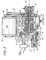
- FIG. 3 there is shown a rotary anode x-ray generating vacuum tube referred to generally as 10 together with a drive motor assembly referred to generally as 100.
- the drive motor assembly provides the necessary rotation of the tube as will be described in detail below.
- the tube 10 and the assembly 100 are adapted for mounting on a gantry of a rotating ' type CT scanner (not shown).
- the x-ray tube 10 comprises an electron gun 20 connected to a high voltage source (not shown) which serves as the cathode of the vacuum tube and a rotating anode assembly 40 which will be described below.with reference to Figure 1.
- the rotating anode assembly 40 includes a rotatable generally disc-shaped stainless steel rotor 42 and stainless steel shaft 44.
- the rotor 42 has a bevelled frontal portion including an annular hardened portion 43, preferably plasma sprayed tungsten, which serves as the target.
- the function of target 43 is to decelerate the high energy electrons emitted by the electron gun 20 to thereby generate X-rays.
- the shaft 44 Extending away from the rotor 42 is the shaft 44 whose remote end is surrounded by a drive pulley 46 for connection to the motor drive assembly 100.
- the shaft 44 includes a concentrically disposed hollow internal shaft 48 as best illustrated in Figure 2.
- the region between the exterior of the internal shaft 48 and the interior of shaft 44 defines an annular passageway 47 for the introduction of a coolant such as water, into the anode assembly 40.
- Passageway 47 extends the length of shaft 44 to the interior of the rotor 42.
- the cooling water is directed radially outward in the interior of the rotor 42 from the interface of the rotor and shaft as shown in Figure 1 and is routed around to internal portions of rotary target 43.
- the water is heated as it flows past the target.
- the heated water then routes through the interior of internal shaft 48 which defines a cylindrical exiting passageway 49 for the discharge of the heated fluid.
- the remote ends of the two shafts are threadably engaged to ensure retention of the internal shaft 48 in concentric relationship inside shaft 44.
- a stainless steel housing 50 which includes base plate 12, sleeve 51, and main flange 52.
- electron gun 20 is mounted through an opening in stainless steel base plate 12.
- Sleeve 51 which is attached to base plate 12 by means of main flange 52 serves as an enclosure for rotor 42 and together with base plate 12 defines a region 60 of high vacuum, i.e., on the order of 10- 7 Torr.
- a small ion pump such as one made by Varian Associates, Palo Alto, CA is mounted within base plate 12 and serves as a getter to help maintain the high vacuum.
- an annular static seal 14 provides the necessary sealing therebetween.
- the anode assembly 40 requires rotation and, hence, creates a far more difficult vacuum sealing problem.
- a magnetic seal assembly 62 which utilizes a magnetic or ferrofluidic seal to provide coaxial liquid sealing about the shaft-44.
- Magnetic fluid as well as magnetic seal assemblies are available from the Ferrof-ucidics Corporation of Nashua, New Hampshire 03061.
- the magnetic ferrofluidic seal assembly 62 is shown in place disposed about shaft 44 in the sectional detailed illustration of Figure 2.
- the ferrofluidic seal 62 includes a pair of annular pole pieces 64, 64' disposed about the shaft 44 and separated from each other by a plurality of magnets 66 sandwiched therebetween and arranged in a circle about the shaft.
- the magnetic pieces 66 are axially polarized.
- Magnetic fluid is placed in the gap between the inner surfaces of the stationary pole pieces 64, 64' and the outer surface of the rotary shaft 44. In the presence of a magnetic field, the ferrofluid assumes the shape of a liquid 0-ring to completely fill the gap. Static sealing between outer portions of the two pole pieces and the interior of housing 50 is provided by means of elastomeric O-rings 68, two embedded in each pole piece.
- Cooling of the magnetic seal assembly 62 is provided by a coolant such as water that is introduced into the assembly at the cooling in port 70.
- a coolant such as water that is introduced into the assembly at the cooling in port 70.
- Port 70 is in fluid communicating relationship by means of a first channel 71 with a pair of annular openings 72, diamond shape in cross-section, one in each pole piece.
- a channel 73 diametrically opposed to the first channel 71, which collects the heated liquid for discharge through cooling out port 74.
- each pole piece is provided with a plurality of parallel annular grooves 75 wherein the high regions 751 adjacent said grooves represent the closest distance between the shaft and the pole pieces and hence, define the region where the ferrofluid is focused.
- Each such annular ring of ferrofluid serves as an independent seal in the system.
- the pressure between each adjacent pair of annular magnetic seals in the pole piece 64', adjacent said evacuated region 60 is at approximately 0 psi, while the pressure gradient across the other pole piece 64 rises incrementally from 0 psi intermediate the two pole pieces 64, 64' to 15 psi or atmospheric pressure (approximately 760 Torr) on the other side.
- FIG 2 also illustrates an annular temporary static seal 76 disposed in the rotor and spaced apart from sleeve 51 of housing 50.
- Temporary seal 76 is a hollow, metal O-ring that can withstand temperatures in excess of 350°C. It serves no purpose in the operation of the x-ray tube, but is used to seal the-evacuated region during a bake-out procedure to assure a high vacuum. This is accomplished before the magnetic seal assembly including magnetic fluid is installed. Assembly of the tube is the subject of a separate European Patent Application filed contemporaneously herewith (EP-A-0136864).
- the anode With the aid of the magnetic fluid, the anode can be rotated in a fashion that permits maintenance of the high vacuum in the evacuated region 60 without the need for bearings inside the high vacuum.
- a pair of high durability bearings 78 separated by a spacer 80 are disposed about the shaft 44 outside of the evacuated region where they are provided with conventional lubricants, assuring long life.
- Adjacent bearings 78 is the drive pulley 46.
- the drive pulley is rotated by a belt 82 which connects to a motor pulley 84 that in turn is driven by a variable speed motor 86 of motor drive assembly 100.
- the motor drive assembly is mounted on a mounting plate 88 which also supports the x-ray tube 10 for rotation on a gantry (not shown) of a rotational type CT scanner.
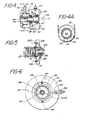
- the belt 82 is also shown in Figure 4A.
- This end view also illustrates the threadable engagement of shaft 44 with internal shaft 48.
- the annular space between the two shafts 44, 48 defines the cold water inlet passageway 47 that serves to cool the anode 40.
- the cylindrical exiting hot water passageway 49 is also shown.
- the engagement of the two shafts 44, 48 is shown in greater detail in Figure 4.
- the coolant is introduced into inlet passageway 47 via input port 471 while the heated liquid exits the anode from cylindrical passageway 49 through exit port 491. This is shown in phantom in Figure 4 since port 491 is out of the plane of the Figure 4 illustration.
- the anode assembly 40 terminates in an end piece 87 which is bolted to end plate 90.
- end piece 87 and end plate 90 Sealing between end piece 87 and end plate 90 is provided by 0- ring 92.
- internal shaft 48 is threadably engaged within the interior of the cylindrical opening of shaft 44 and secured therein by means of spring loaded assembly 94.
- the shaft 44 is also provided with a spring loaded assembly 96 at its remote end biased against end plate 90.
- Annular water seals 98, 99 are provided for shaft 44 and internal shaft 48, respectively.
- a third coolant circuit is provided in connection with cathode 20 which will be described in detail below, making reference to Figures 3 and 5.
- Cathode 20 includes a filament 22 which in conventional fashion emits high energy electrons which accelerate along path 24 on their way to the target 43 of the rotor 42. As was stated earlier, only a small percentage of the electrons that are decelerated by the target generate x-rays. These exit the tube through a window 26 along path 28.
- the window 26 is simply a thinned out portion of the stainless steel housing 50 or more preferably, made of beryllium. As discussed in U.S. Patent 4,309,637 to Fetter, there will be some scatter of secondary electrons emitted at the region of the incidence of the electron beam.
- a hood 210 is provided around the target region to collect the scattered electrons. It has been found that hood 210 quickly heats up to high temperatures and for this reason a separate cooling circuit, as shown in Figure 5, is provided.
- a cold water inlet 212 is mounted in the base plate 12 which connects to the hood 210 by means of passageway 214. The entering water is routed around the hood through annular opening 216 and the heated water exits through passageway 218 through base plate 12 and eventually out through exit port 220.
- the x-ray tube described herein is provided with three separate water circuits: one for the magnetic seal assembly 62, another for the rotating anode assembly 40 and finally, a third, for the hood 210.
- a donut-shaped ballast volume 310 is fitted about shaft 44 in concentric relationship with bearings 78. The ballast volume is in pressure communicating relationship with the magnetic seal assembly 62 via connector tube 312.
- the ballast volume is also provided with a T-fitting 314 one stem of which is connected to a gauge (not shown) for reading the internal pressure in the volume while the other stem is connected to a bleed off valve (also not shown) for periodically relieving the pressure that builds up inside the volume.
- a gauge not shown
- a bleed off valve also not shown
- the ballast volume 310 is connected to mounting plate 88 by a series of bolts 316 disposed about a circle defined by the annular shape of the volume.
Landscapes
- Physics & Mathematics (AREA)
- Fluid Mechanics (AREA)
- X-Ray Techniques (AREA)
Claims (3)
Applications Claiming Priority (2)
| Application Number | Priority Date | Filing Date | Title |
|---|---|---|---|
| US533706 | 1983-09-19 | ||
| US06/533,706 US4577340A (en) | 1983-09-19 | 1983-09-19 | High vacuum rotating anode X-ray tube |
Publications (3)
| Publication Number | Publication Date |
|---|---|
| EP0136149A2 EP0136149A2 (de) | 1985-04-03 |
| EP0136149A3 EP0136149A3 (en) | 1986-02-26 |
| EP0136149B1 true EP0136149B1 (de) | 1989-01-04 |
Family
ID=24127118
Family Applications (1)
| Application Number | Title | Priority Date | Filing Date |
|---|---|---|---|
| EP84306374A Expired EP0136149B1 (de) | 1983-09-19 | 1984-09-18 | Drehanoden-Röntgenröhre mit Hochvakuum |
Country Status (4)
| Country | Link |
|---|---|
| US (1) | US4577340A (de) |
| EP (1) | EP0136149B1 (de) |
| JP (2) | JPS6086741A (de) |
| DE (1) | DE3475987D1 (de) |
Families Citing this family (36)
| Publication number | Priority date | Publication date | Assignee | Title |
|---|---|---|---|---|
| NL8400072A (nl) * | 1984-01-10 | 1985-08-01 | Philips Nv | Roentgenbuis met een spiraalgroeflager. |
| DE3542127A1 (de) * | 1985-11-28 | 1987-06-04 | Siemens Ag | Roentgenstrahler |
| US5018181A (en) * | 1987-06-02 | 1991-05-21 | Coriolis Corporation | Liquid cooled rotating anodes |
| US5111493A (en) * | 1988-11-25 | 1992-05-05 | Wisconsin Alumni Research Foundation | Portable X-ray system with ceramic tube |
| US4894007A (en) * | 1988-12-12 | 1990-01-16 | Thomson Consumer Electronics | Apparatus for providing fluid to a rotatable member |
| US4945562A (en) * | 1989-04-24 | 1990-07-31 | General Electric Company | X-ray target cooling |
| US5388142A (en) * | 1991-11-27 | 1995-02-07 | X-Cel X-Ray Corporation | Portable radiographic device |
| US5283823A (en) * | 1991-11-27 | 1994-02-01 | X-Cel X-Ray Corporation | Portable radiographic device |
| US5340122A (en) * | 1992-06-22 | 1994-08-23 | Ferrofluidics Corporation | Differentially-pumped ferrofluidic seal |
| US5799951A (en) * | 1996-11-21 | 1998-09-01 | Varian Associates, Inc. | Rotating sealing device |
| US6252934B1 (en) * | 1999-03-09 | 2001-06-26 | Teledyne Technologies Incorporated | Apparatus and method for cooling a structure using boiling fluid |
| RU2195739C2 (ru) * | 2000-02-25 | 2002-12-27 | Государственный научно-исследовательский институт Научно-производственного объединения "Луч" | Анод рентгеновской трубки |
| US6857635B1 (en) * | 2001-10-18 | 2005-02-22 | Ferrotec (Usa) Corporation | Ultra high vacuum ferrofluidic seals and method of manufacture |
| US7343002B1 (en) * | 2003-02-05 | 2008-03-11 | Varian Medical Systems Technologies, Inc. | Bearing assembly |
| DE10353964B4 (de) * | 2003-11-19 | 2013-10-10 | Siemens Aktiengesellschaft | Röntgenröhre mit Drehanode |
| US20050226385A1 (en) * | 2004-03-30 | 2005-10-13 | Simpson James E | X-ray tube for a computed tomography system and method |
| US7197115B2 (en) * | 2004-08-10 | 2007-03-27 | General Electric Company | Cantilever and straddle x-ray tube configurations for a rotating anode with vacuum transition chambers |
| US7377695B2 (en) * | 2005-10-14 | 2008-05-27 | General Electric Company | Integral duplex bearings for rotating x-ray anode |
| US7502446B2 (en) * | 2005-10-18 | 2009-03-10 | Alft Inc. | Soft x-ray generator |
| US20070138747A1 (en) * | 2005-12-15 | 2007-06-21 | General Electric Company | Multi-stage ferrofluidic seal having one or more space-occupying annulus assemblies situated within its interstage spaces for reducing the gas load therein |
| TW200741125A (en) * | 2006-03-31 | 2007-11-01 | Eagle Ind Co Ltd | Device for sealing magnetic fluid |
| US7519158B2 (en) * | 2006-12-12 | 2009-04-14 | General Electric Company | Pumping schemes for X-ray tubes with ferrofluid seals |
| US7587027B2 (en) * | 2006-12-23 | 2009-09-08 | X-Cel X-Ray | Method and apparatus for determining and displaying x-ray radiation by a radiographic device |
| US7656236B2 (en) * | 2007-05-15 | 2010-02-02 | Teledyne Wireless, Llc | Noise canceling technique for frequency synthesizer |
| CN101377985B (zh) * | 2007-08-31 | 2012-08-22 | 湖南维格磁流体股份有限公司 | 中高压电力开关设备用动密封装置 |
| US7585109B2 (en) * | 2007-11-21 | 2009-09-08 | X-Cel X-Ray | Arm linkage system for a radiographic device |
| US8179045B2 (en) * | 2008-04-22 | 2012-05-15 | Teledyne Wireless, Llc | Slow wave structure having offset projections comprised of a metal-dielectric composite stack |
| US8382118B2 (en) * | 2008-10-09 | 2013-02-26 | Rigaku Innovative Technologies, Inc. | Magnetic fluid seal with centering of bearing and shaft by compressible member |
| US20100128848A1 (en) * | 2008-11-21 | 2010-05-27 | General Electric Company | X-ray tube having liquid lubricated bearings and liquid cooled target |
| US7974384B2 (en) * | 2009-04-14 | 2011-07-05 | General Electric Company | X-ray tube having a ferrofluid seal and method of assembling same |
| US7903787B2 (en) * | 2009-04-14 | 2011-03-08 | General Electric Company | Air-cooled ferrofluid seal in an x-ray tube and method of fabricating same |
| US8009806B2 (en) * | 2009-07-13 | 2011-08-30 | General Electric Company | Apparatus and method of cooling a liquid metal bearing in an x-ray tube |
| US8295443B2 (en) | 2010-07-07 | 2012-10-23 | King Fahd University Of Petroleum And Minerals | X-ray system with superconducting anode |
| US9202660B2 (en) | 2013-03-13 | 2015-12-01 | Teledyne Wireless, Llc | Asymmetrical slow wave structures to eliminate backward wave oscillations in wideband traveling wave tubes |
| DE102015220101A1 (de) * | 2015-10-15 | 2017-04-20 | Minebea Co., Ltd. | Drehanodenlageranordnung und Drehanode für eine Röntgenröhre |
| US20250372336A1 (en) * | 2024-05-29 | 2025-12-04 | Varex Imaging Corporation | Anode rotation sensing in x-ray tubes |
Family Cites Families (16)
| Publication number | Priority date | Publication date | Assignee | Title |
|---|---|---|---|---|
| US2754168A (en) * | 1956-07-10 | atlee | ||
| US2329317A (en) * | 1941-03-19 | 1943-09-14 | Gen Electric X Ray Corp | Method of conditioning anodes |
| GB783881A (en) * | 1954-03-05 | 1957-10-02 | Vickers Electrical Co Ltd | Improvements relating to shaft and like seals |
| US3546511A (en) * | 1967-07-31 | 1970-12-08 | Rigaku Denki Co Ltd | Cooling system for a rotating anode of an x-ray tube |
| US4094563A (en) * | 1967-08-09 | 1978-06-13 | Westinghouse Electric Corp. | Method of fabricating an electron tube |
| GB1445791A (en) * | 1973-02-21 | 1976-08-11 | Kernforschungsanlage Juelich | X-ray tube |
| US4066310A (en) * | 1977-01-03 | 1978-01-03 | Zenith Radio Corporation | Method for introducing a high voltage conductor into a television cathode ray tube |
| FR2386958A1 (fr) * | 1977-04-06 | 1978-11-03 | Cgr Mev | Dispositif compact d'irradiation utilisant un accelerateur lineaire de particules chargees |
| DE2813935A1 (de) * | 1978-03-31 | 1979-10-11 | Siemens Ag | Roentgenroehre hoher leistung mit einer drehanode |
| US4165472A (en) * | 1978-05-12 | 1979-08-21 | Rockwell International Corporation | Rotating anode x-ray source and cooling technique therefor |
| NL7902477A (nl) * | 1979-03-30 | 1980-10-02 | Philips Nv | Roentgenbuis met een magnetisch gelagerde draaianode. |
| DE2928993C2 (de) * | 1979-07-18 | 1982-12-09 | Philips Patentverwaltung Gmbh, 2000 Hamburg | Verfahren zur Herstellung einer Röntgenröhren-Drehanode |
| US4289317A (en) * | 1979-07-25 | 1981-09-15 | Peerless Pump Division, Indian Head, Inc. | Pump shaft closure |
| US4309637A (en) * | 1979-11-13 | 1982-01-05 | Emi Limited | Rotating anode X-ray tube |
| DE3019864C2 (de) * | 1980-05-23 | 1982-05-27 | Kraftwerk Union AG, 4330 Mülheim | Generatorläufer, insbesondere Turbogeneratorläufer, mit supraleitender Erregerwicklung |
| US4405876A (en) * | 1981-04-02 | 1983-09-20 | Iversen Arthur H | Liquid cooled anode x-ray tubes |
-
1983
- 1983-09-19 US US06/533,706 patent/US4577340A/en not_active Expired - Lifetime
-
1984
- 1984-09-18 DE DE8484306374T patent/DE3475987D1/de not_active Expired
- 1984-09-18 JP JP59194075A patent/JPS6086741A/ja active Pending
- 1984-09-18 EP EP84306374A patent/EP0136149B1/de not_active Expired
- 1984-09-18 JP JP59194076A patent/JPS6086742A/ja active Pending
Also Published As
| Publication number | Publication date |
|---|---|
| JPS6086742A (ja) | 1985-05-16 |
| DE3475987D1 (en) | 1989-02-09 |
| JPS6086741A (ja) | 1985-05-16 |
| US4577340A (en) | 1986-03-18 |
| EP0136149A3 (en) | 1986-02-26 |
| EP0136149A2 (de) | 1985-04-03 |
Similar Documents
| Publication | Publication Date | Title |
|---|---|---|
| US4577340A (en) | High vacuum rotating anode X-ray tube | |
| US4625324A (en) | High vacuum rotating anode x-ray tube | |
| US4993055A (en) | Rotating X-ray tube with external bearings | |
| US4309637A (en) | Rotating anode X-ray tube | |
| JP4028601B2 (ja) | X線管 | |
| US6181765B1 (en) | X-ray tube assembly | |
| US4674109A (en) | Rotating anode x-ray tube device | |
| US20080137812A1 (en) | Convectively cooled x-ray tube target and method of making same | |
| US4501566A (en) | Method for assembling a high vacuum rotating anode X-ray tube | |
| EP0715333B1 (de) | Anordnung von Röntgenröhren | |
| US4878235A (en) | High intensity x-ray source using bellows | |
| US5384820A (en) | Journal bearing and radiation shield for rotating housing and anode/stationary cathode X-ray tubes | |
| US6041100A (en) | Cooling device for x-ray tube bearing assembly | |
| US7558375B2 (en) | Stationary cathode in rotating frame x-ray tube | |
| EP0938249A2 (de) | Röntgenstrahlrohre | |
| US6751293B1 (en) | Rotary component support system | |
| US4584699A (en) | X-ray anode assembly | |
| US7515687B2 (en) | Compact source with very bright X-ray beam | |
| CN210123714U (zh) | X射线管及医疗成像设备 | |
| US3398307A (en) | Electron beam X-ray generator with rotatable target movable along axis of rotation | |
| US20090052627A1 (en) | System and method for collecting backscattered electrons in an x-ray tube | |
| US7693264B2 (en) | Antechamber control reducing leak through ferrofluid seals | |
| EP1236219B1 (de) | Drehanode mit kompakter abschirmvorrichtung | |
| US12597580B2 (en) | X-ray generating apparatus and imaging device | |
| CN121964456A (zh) | 一种x射线球管结构 |
Legal Events
| Date | Code | Title | Description |
|---|---|---|---|
| PUAI | Public reference made under article 153(3) epc to a published international application that has entered the european phase |
Free format text: ORIGINAL CODE: 0009012 |
|
| AK | Designated contracting states |
Designated state(s): DE FR GB NL |
|
| PUAL | Search report despatched |
Free format text: ORIGINAL CODE: 0009013 |
|
| AK | Designated contracting states |
Designated state(s): DE FR GB NL |
|
| 17P | Request for examination filed |
Effective date: 19860805 |
|
| 17Q | First examination report despatched |
Effective date: 19880204 |
|
| GRAA | (expected) grant |
Free format text: ORIGINAL CODE: 0009210 |
|
| AK | Designated contracting states |
Kind code of ref document: B1 Designated state(s): DE FR GB NL |
|
| REF | Corresponds to: |
Ref document number: 3475987 Country of ref document: DE Date of ref document: 19890209 |
|
| ET | Fr: translation filed | ||
| PLBE | No opposition filed within time limit |
Free format text: ORIGINAL CODE: 0009261 |
|
| STAA | Information on the status of an ep patent application or granted ep patent |
Free format text: STATUS: NO OPPOSITION FILED WITHIN TIME LIMIT |
|
| 26N | No opposition filed | ||
| PGFP | Annual fee paid to national office [announced via postgrant information from national office to epo] |
Ref country code: GB Payment date: 19970909 Year of fee payment: 14 Ref country code: FR Payment date: 19970909 Year of fee payment: 14 |
|
| PGFP | Annual fee paid to national office [announced via postgrant information from national office to epo] |
Ref country code: DE Payment date: 19970926 Year of fee payment: 14 |
|
| PGFP | Annual fee paid to national office [announced via postgrant information from national office to epo] |
Ref country code: NL Payment date: 19970929 Year of fee payment: 14 |
|
| PG25 | Lapsed in a contracting state [announced via postgrant information from national office to epo] |
Ref country code: GB Free format text: LAPSE BECAUSE OF NON-PAYMENT OF DUE FEES Effective date: 19980918 |
|
| PG25 | Lapsed in a contracting state [announced via postgrant information from national office to epo] |
Ref country code: NL Free format text: LAPSE BECAUSE OF NON-PAYMENT OF DUE FEES Effective date: 19990401 |
|
| GBPC | Gb: european patent ceased through non-payment of renewal fee |
Effective date: 19980918 |
|
| PG25 | Lapsed in a contracting state [announced via postgrant information from national office to epo] |
Ref country code: FR Free format text: LAPSE BECAUSE OF NON-PAYMENT OF DUE FEES Effective date: 19990531 |
|
| NLV4 | Nl: lapsed or anulled due to non-payment of the annual fee |
Effective date: 19990401 |
|
| PG25 | Lapsed in a contracting state [announced via postgrant information from national office to epo] |
Ref country code: DE Free format text: LAPSE BECAUSE OF NON-PAYMENT OF DUE FEES Effective date: 19990701 |
|
| REG | Reference to a national code |
Ref country code: FR Ref legal event code: ST |