EP0136520A2 - Dispositif pour l'enregistrement de valeurs densitométriques d'une bande de contrôle - Google Patents
Dispositif pour l'enregistrement de valeurs densitométriques d'une bande de contrôle Download PDFInfo
- Publication number
- EP0136520A2 EP0136520A2 EP84110087A EP84110087A EP0136520A2 EP 0136520 A2 EP0136520 A2 EP 0136520A2 EP 84110087 A EP84110087 A EP 84110087A EP 84110087 A EP84110087 A EP 84110087A EP 0136520 A2 EP0136520 A2 EP 0136520A2
- Authority
- EP
- European Patent Office
- Prior art keywords
- densitometer
- control strip
- absolute position
- recording
- support table
- Prior art date
- Legal status (The legal status is an assumption and is not a legal conclusion. Google has not performed a legal analysis and makes no representation as to the accuracy of the status listed.)
- Granted
Links
Images
Classifications
-
- G—PHYSICS
- G01—MEASURING; TESTING
- G01N—INVESTIGATING OR ANALYSING MATERIALS BY DETERMINING THEIR CHEMICAL OR PHYSICAL PROPERTIES
- G01N21/00—Investigating or analysing materials by the use of optical means, i.e. using sub-millimetre waves, infrared, visible or ultraviolet light
- G01N21/17—Systems in which incident light is modified in accordance with the properties of the material investigated
- G01N21/59—Transmissivity
- G01N21/5907—Densitometers
-
- B—PERFORMING OPERATIONS; TRANSPORTING
- B41—PRINTING; LINING MACHINES; TYPEWRITERS; STAMPS
- B41F—PRINTING MACHINES OR PRESSES
- B41F33/00—Indicating, counting, warning, control or safety devices
- B41F33/0036—Devices for scanning or checking the printed matter for quality control
Definitions
- the invention relates to a device of the type mentioned in the preamble of claim 1.
- the control strip reproduces the colors used to produce a colored image, for example a printed sheet.
- the color density of the individual color fields of the control strip can be measured using a densitometer. For the evaluation of each measurement, it is necessary that the associated color field, ie. H. the measurement location on the control strip is known.
- a device of the generic type is already known in which the densitometer is automatically moved along the control strip for each measurement.
- the entire control strip is measured field by field.
- the densitometer is designed in such a way that it can recognize the color field boundaries and thus count the color fields passed over. It is a relatively complex system which is generally only installed in automatic densitometer systems, such as those used in large printers for monitoring several printing machines.
- a further disadvantage of the known device is considered that, because of the use of the counting principle for determining the measuring location, the densitometer is used for each measurement from an initial position the control strip must be moved to the desired measuring location.
- the measuring location thus results as a relative position, which is related to a very specific starting position, which must be sought first for each measuring process.
- the known device can therefore in particular not be used in conjunction with a hand-held densitometer, the advantage of which is that it can be placed at any time on any color field whose color values are to be measured densitometrically.
- An arrangement of absolute position sensors with a course corresponding to the course of the control strip is assigned to the support table. This arrangement is such that when the control strip carrier is placed on the support table and aligned on it, the respective color fields of the control strip correspond to certain absolute position sensors. If the densitometer is moved over a certain color field, the corresponding absolute position sensor emits a signal which can be used to determine the measurement location in the evaluation device.
- Such absolute position encoders are technically very simple and inexpensive to represent.
- the device according to the invention makes it possible to determine each measuring location absolutely, so that a time-consuming movement of the control strip from a certain starting point to the desired measuring location is no longer necessary for each measurement.
- the device according to the invention can in particular also be used in connection with simple and inexpensive handheld densitometers, the advantage of which is that they can be placed directly on a desired measuring location.
- a magnet is arranged on the densitometer near its reading head and the absolute position sensors are electromagnetic sensors which are electrically connected to the evaluation device. Both the electromagnetic sensors and the magnet are very simple and cheap commercially available components, which are also very insensitive and therefore easy to maintain.
- the absolute position sensors are preferably arranged below the support table and in a row parallel to the control strip.
- the arrangement below the support table means that they are not exposed to the contamination that is generally unavoidable in a printing company. It only has to be ensured that an activation of the absolute position encoder is possible through the support table.
- the marks for aligning the control strip carrier can be designed as optical markings or as stops.
- the device according to the invention can in principle comprise densitometers of any type.
- the densitometer is a manual densitometer which is connected to a stationary evaluation device.
- the advantage of the simple, easy-to-use manual densitometer is thus fully retained, while at the same time the performance of an automatic densitometer system which is generally much more expensive is achieved.
- the operator of the printing press can carry out his measurement directly at this at any time that is deemed expedient and at precisely the location of the control strip, which the operator selected on the basis of his experience with the machine to be tested and with the material used for the printing sheet.
- the evaluation device preferably comprises a desktop computer, a printer and a monitor.
- the desktop computer (preferably a basic computer) has a memory so that it can provide the time, the date, technical data of the printing press, number of the measurement series and other information essential for the log output by the printer. In addition, it should make previously acquired data or comparison data visible on the screen, which should facilitate the interpretation of the newly measured data.
- the view appears on the screen bar made data of the control strip with reference to a horizontal line 0 and two of these adjacent strips, which limit the variable tolerance field to be observed, so that the operator can immediately identify any "points" that fall outside the tolerance band; A reference information on the measuring locations which correspond to the recording points in the printing machine also appears on the screen.
- the person operating the handheld densitometer will preferably monitor the areas of the control strip which, based on their experience and knowledge of the printing press and the material, they know that there is a certain probability that they will fall outside the specified, stored tolerance band. After making changes or adjustments, the operator can compare the measured values with previously stored values in order to get to the desired quality level in the shortest possible time (which is available in the form of stored target data) and to keep this level for the duration of several measurement runs through constant To be able to receive control interventions on the printing press.
- the memory of the computer is supplied with data from the printing machine gives the possibility of producing a protocol by means of the printer as soon as a measured value acquisition is carried out, whereby an irrefutable document is provided which is used to determine the quality of a particular lot of printed sheets and can serve as proof of the work performed.
- the device according to the invention is shown and described in connection with a manual densitometer.
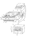
- the figure shows a schematic representation of a device with a support table, a manual densitometer, an arrangement of absolute position sensors assigned to the support table, and an evaluation unit connected to the manual densitometer and the absolute position sensors.
- the printed sheet is placed on a support table 1b; its control strip 1 is positioned exactly by means of the optical markings 1a.
- an arrangement 2 of electromagnetic sensors 2a is provided below the support table 1b; these are activated by the magnet 3a arranged on the hand-held densitometer 3 near the reading head in each measurement carried out by means of the hand-held densitometer 3 and give electronic impulses to the devices 4, 5, 6 connected to the hand-held densitometer, thereby giving a written indication of the measuring position on the printer 4 output protocol 4a, a display of the position on the screen 6 and a comparison with target measured values or previously recorded and stored in the computer 5.
- the hand densitometer 3 can be of a known type; it is provided with a connecting cable 8 and a magnet 3a. When it is in a position for optical measurement recording, the magnet 3a activates the magnetic sensors 2a connected to the printer 4 via cable 9.
- the printer is coupled to an interface (RS 232 C) and connected to the computer 5 and the screen 6 by means of the cables 10, 11.
- the electronic devices te 2, 3, 4, 5, 6 are connected to an electrical power source 7 via cables 7a, 7b, 7c and 8, 9, respectively.
- the invention does not rule out that the manual densitometer 3 of the reflection densitometer type is replaced by a densitometer of another type, the measured values output in the form of pulses being processed by the devices 4, 5, 6 connected to it.
- the interface (RS 232 C) can also be combined with the computer 5 to form one device.
- these appear on the screen 6 with reference to a line 0 as stripes in an upper positive field and a lower negative field, the corresponding permissible tolerance ranges being indicated by the bands 6b, 6c are displayed so that the "dots" 6d which fall outside these bands 6b, 6c are immediately recognized; otherwise, the measurement location 6e appears for each measured value.
- the individual components 4, 5, 6 can also be structurally connected so that they form a single block, possibly combined with the support plate 1b, arranged in the space below it; in addition, the device according to the invention allows different connections between the electronic devices 4, 2, 5, 6 and the manual densitometer 3.
Landscapes
- Engineering & Computer Science (AREA)
- Quality & Reliability (AREA)
- Physics & Mathematics (AREA)
- Health & Medical Sciences (AREA)
- Life Sciences & Earth Sciences (AREA)
- Chemical & Material Sciences (AREA)
- Analytical Chemistry (AREA)
- Biochemistry (AREA)
- General Health & Medical Sciences (AREA)
- General Physics & Mathematics (AREA)
- Immunology (AREA)
- Pathology (AREA)
- Inking, Control Or Cleaning Of Printing Machines (AREA)
Applications Claiming Priority (2)
| Application Number | Priority Date | Filing Date | Title |
|---|---|---|---|
| IT483583 | 1983-08-25 | ||
| IT04835/83A IT1172552B (it) | 1983-08-25 | 1983-08-25 | Sistema di rilievi densitometrici su striscie di controllo di stampe |
Publications (3)
| Publication Number | Publication Date |
|---|---|
| EP0136520A2 true EP0136520A2 (fr) | 1985-04-10 |
| EP0136520A3 EP0136520A3 (en) | 1986-02-05 |
| EP0136520B1 EP0136520B1 (fr) | 1989-10-25 |
Family
ID=11114670
Family Applications (1)
| Application Number | Title | Priority Date | Filing Date |
|---|---|---|---|
| EP84110087A Expired EP0136520B1 (fr) | 1983-08-25 | 1984-08-23 | Dispositif pour l'enregistrement de valeurs densitométriques d'une bande de contrôle |
Country Status (3)
| Country | Link |
|---|---|
| EP (1) | EP0136520B1 (fr) |
| DE (1) | DE3480300D1 (fr) |
| IT (1) | IT1172552B (fr) |
Cited By (4)
| Publication number | Priority date | Publication date | Assignee | Title |
|---|---|---|---|---|
| EP0353624A3 (en) * | 1988-08-03 | 1990-09-05 | M.A.N.-Roland Druckmaschinen Aktiengesellschaft | Device for evaluating copies |
| EP0356705A3 (fr) * | 1988-08-30 | 1991-05-08 | M.A.N.-ROLAND Druckmaschinen Aktiengesellschaft | Lecture de données pour un dispositif de réglage de l'encre |
| EP0410253A3 (en) * | 1989-07-28 | 1991-07-31 | Man Roland Druckmaschinen Ag | Device for carrying out a comprehensive quality control on printed sheets |
| AT413681B (de) * | 2003-02-05 | 2006-05-15 | Roland Man Druckmasch | Farbfernsteuerung |
Family Cites Families (7)
| Publication number | Priority date | Publication date | Assignee | Title |
|---|---|---|---|---|
| FR1200742A (fr) * | 1956-09-05 | 1959-12-23 | Crosfield J F Ltd | Perfectionnements aux procédés d'impression |
| US3141727A (en) * | 1962-12-14 | 1964-07-21 | Jr Harry L Devereaux | Film-strip density curve plotting device |
| US3367230A (en) * | 1963-12-04 | 1968-02-06 | Welch Scient Company | Light density scanning device |
| FR1529112A (fr) * | 1967-06-22 | 1968-06-14 | Gl Upravlenie Energetiki I Ele | Capteur de paramètres de mouvement relatif d'objets |
| US3995958A (en) * | 1975-07-21 | 1976-12-07 | Hallmark Cards, Incorporated | Automatic densitometer and method of color control in multi-color printing |
| US4110611A (en) * | 1975-12-17 | 1978-08-29 | Candid Logic, Inc. | Optical position transducer |
| BE849338A (fr) * | 1976-12-13 | 1977-04-01 | Appareil a visualiser les mouvements de la pedale d'embrayage |
-
1983
- 1983-08-25 IT IT04835/83A patent/IT1172552B/it active
-
1984
- 1984-08-23 DE DE8484110087T patent/DE3480300D1/de not_active Expired
- 1984-08-23 EP EP84110087A patent/EP0136520B1/fr not_active Expired
Cited By (4)
| Publication number | Priority date | Publication date | Assignee | Title |
|---|---|---|---|---|
| EP0353624A3 (en) * | 1988-08-03 | 1990-09-05 | M.A.N.-Roland Druckmaschinen Aktiengesellschaft | Device for evaluating copies |
| EP0356705A3 (fr) * | 1988-08-30 | 1991-05-08 | M.A.N.-ROLAND Druckmaschinen Aktiengesellschaft | Lecture de données pour un dispositif de réglage de l'encre |
| EP0410253A3 (en) * | 1989-07-28 | 1991-07-31 | Man Roland Druckmaschinen Ag | Device for carrying out a comprehensive quality control on printed sheets |
| AT413681B (de) * | 2003-02-05 | 2006-05-15 | Roland Man Druckmasch | Farbfernsteuerung |
Also Published As
| Publication number | Publication date |
|---|---|
| IT1172552B (it) | 1987-06-18 |
| DE3480300D1 (en) | 1989-11-30 |
| IT8304835A0 (it) | 1983-08-25 |
| EP0136520A3 (en) | 1986-02-05 |
| EP0136520B1 (fr) | 1989-10-25 |
Similar Documents
| Publication | Publication Date | Title |
|---|---|---|
| EP0064024B1 (fr) | Procédé et dispositif pour l'analyse colorimétrique d'une bande de mesure d'impression colorée | |
| EP0410253A2 (fr) | Dispositif pour effectuer un vaste contrôle de qualité de feuilles imprimées | |
| EP0149424A2 (fr) | Procédé et dispositif pour le contrôle de la qualité d'impression et ruban test coloré pour ce contrôle | |
| DE2253189B2 (de) | Verfahren und Vorrichtung zur maschinellen Kontrolle der Farbdichte von auf eine laufende Bahn aufgebrachten Druckfarben | |
| DE2930438A1 (de) | Verfahren zum voreinstellen des registers bei tiefdruckmaschinen. | |
| EP0356705B1 (fr) | Lecture de données pour un dispositif de réglage de l'encre | |
| DE3830731A1 (de) | Vorrichtung zur farbmessung | |
| DE19716066C1 (de) | Handmeßgerät für Reflexionsmessungen auf Druckbogen und Testformen | |
| AT394781B (de) | Inkrementales messsystem | |
| EP0136520B1 (fr) | Dispositif pour l'enregistrement de valeurs densitométriques d'une bande de contrôle | |
| EP0007009A1 (fr) | Procédé d'affichage de grandeurs de réglage pour la commande d'une machine à imprimer à cylindres rotatifs | |
| EP0860276B1 (fr) | Procédé et dispositif de contrôle de qualité | |
| DE2901980C2 (de) | Einrichtung zum Steuern des Farbwerkes einer Bogenoffsetdruckmaschine | |
| DE3801860C2 (de) | Vorrichtung zur Untersuchung einer Oberfläche eines fortlaufend bewegten Bandmaterials | |
| DE1298726B (de) | Registriermessgeraet fuer Messungen an sich bewegenden Materialstreifen | |
| DE1499399C3 (de) | Gerät zur automatischen Ermittlung der Registrierdauer eines Ereignisses aus Balkendiagrammen | |
| DE2557944C3 (de) | Anordnung zur Erzeugung von Austastsignalen für die Registerregelung | |
| DE2313528B2 (de) | Vorrichtung zum schnellen Erfassen und Charakterisieren von Farbtönen opaker oder transparenter Bereiche auf schnellaufenden, durchgehend oder partiell eingefärbten Materialbahnen | |
| DE2238007A1 (de) | Geraet zur kontrolle der konstanz der farbgebung von druckbogen | |
| DE3219500C2 (fr) | ||
| DE3736629C2 (fr) | ||
| DE1965601C3 (de) | Vorrichtung zur Messung kreisförmiger optisch unterscheidbarer Flächen in Bakterienkulturen | |
| EP0833166A2 (fr) | Dispositif pour tester la fonction d'un seul aimant dans un appareil électromagnétique | |
| DE4334883C2 (de) | Vorrichtung zur Überwachung von Schreib- oder Zeichengeräten, insbesondere in Plottern, Registriergeräten oder ähnlichen automatisch arbeitenden Systemen | |
| DE3112706C2 (de) | Registrieranordnung |
Legal Events
| Date | Code | Title | Description |
|---|---|---|---|
| PUAI | Public reference made under article 153(3) epc to a published international application that has entered the european phase |
Free format text: ORIGINAL CODE: 0009012 |
|
| AK | Designated contracting states |
Designated state(s): AT BE CH DE FR GB IT LI LU NL SE |
|
| RBV | Designated contracting states (corrected) |
Designated state(s): CH DE FR GB IT LI NL |
|
| PUAL | Search report despatched |
Free format text: ORIGINAL CODE: 0009013 |
|
| AK | Designated contracting states |
Designated state(s): CH DE FR GB IT LI NL |
|
| 17P | Request for examination filed |
Effective date: 19860731 |
|
| 17Q | First examination report despatched |
Effective date: 19880420 |
|
| GRAA | (expected) grant |
Free format text: ORIGINAL CODE: 0009210 |
|
| AK | Designated contracting states |
Kind code of ref document: B1 Designated state(s): CH DE FR GB IT LI NL |
|
| PG25 | Lapsed in a contracting state [announced via postgrant information from national office to epo] |
Ref country code: NL Effective date: 19891025 |
|
| REF | Corresponds to: |
Ref document number: 3480300 Country of ref document: DE Date of ref document: 19891130 |
|
| GBT | Gb: translation of ep patent filed (gb section 77(6)(a)/1977) | ||
| ITF | It: translation for a ep patent filed | ||
| ET | Fr: translation filed | ||
| NLV1 | Nl: lapsed or annulled due to failure to fulfill the requirements of art. 29p and 29m of the patents act | ||
| PGFP | Annual fee paid to national office [announced via postgrant information from national office to epo] |
Ref country code: GB Payment date: 19900723 Year of fee payment: 7 |
|
| PGFP | Annual fee paid to national office [announced via postgrant information from national office to epo] |
Ref country code: FR Payment date: 19900809 Year of fee payment: 7 |
|
| PGFP | Annual fee paid to national office [announced via postgrant information from national office to epo] |
Ref country code: DE Payment date: 19900816 Year of fee payment: 7 |
|
| PLBE | No opposition filed within time limit |
Free format text: ORIGINAL CODE: 0009261 |
|
| STAA | Information on the status of an ep patent application or granted ep patent |
Free format text: STATUS: NO OPPOSITION FILED WITHIN TIME LIMIT |
|
| ITTA | It: last paid annual fee | ||
| 26N | No opposition filed | ||
| PGFP | Annual fee paid to national office [announced via postgrant information from national office to epo] |
Ref country code: CH Payment date: 19901123 Year of fee payment: 7 |
|
| PG25 | Lapsed in a contracting state [announced via postgrant information from national office to epo] |
Ref country code: GB Effective date: 19910823 |
|
| PG25 | Lapsed in a contracting state [announced via postgrant information from national office to epo] |
Ref country code: LI Effective date: 19910831 Ref country code: CH Effective date: 19910831 |
|
| GBPC | Gb: european patent ceased through non-payment of renewal fee | ||
| PG25 | Lapsed in a contracting state [announced via postgrant information from national office to epo] |
Ref country code: FR Effective date: 19920430 |
|
| REG | Reference to a national code |
Ref country code: CH Ref legal event code: PL |
|
| PG25 | Lapsed in a contracting state [announced via postgrant information from national office to epo] |
Ref country code: DE Effective date: 19920501 |
|
| REG | Reference to a national code |
Ref country code: FR Ref legal event code: ST |