EP0136787A1 - Presse à double-cylindre pour la formation de couches de fibres - Google Patents
Presse à double-cylindre pour la formation de couches de fibres Download PDFInfo
- Publication number
- EP0136787A1 EP0136787A1 EP84305340A EP84305340A EP0136787A1 EP 0136787 A1 EP0136787 A1 EP 0136787A1 EP 84305340 A EP84305340 A EP 84305340A EP 84305340 A EP84305340 A EP 84305340A EP 0136787 A1 EP0136787 A1 EP 0136787A1
- Authority
- EP
- European Patent Office
- Prior art keywords
- cages
- tank
- tanks
- fibres
- cage
- Prior art date
- Legal status (The legal status is an assumption and is not a legal conclusion. Google has not performed a legal analysis and makes no representation as to the accuracy of the status listed.)
- Granted
Links
- 230000015572 biosynthetic process Effects 0.000 title claims abstract description 14
- 239000004033 plastic Substances 0.000 claims description 9
- 239000002184 metal Substances 0.000 claims description 3
- 230000007423 decrease Effects 0.000 claims 1
- 239000007788 liquid Substances 0.000 abstract description 34
- 239000000835 fiber Substances 0.000 abstract description 18
- 239000002699 waste material Substances 0.000 abstract description 11
- 230000018044 dehydration Effects 0.000 abstract description 9
- 238000006297 dehydration reaction Methods 0.000 abstract description 9
- 230000006835 compression Effects 0.000 abstract description 7
- 238000007906 compression Methods 0.000 abstract description 7
- 208000005156 Dehydration Diseases 0.000 description 8
- 238000010276 construction Methods 0.000 description 6
- 239000004744 fabric Substances 0.000 description 6
- 238000011282 treatment Methods 0.000 description 4
- 230000000694 effects Effects 0.000 description 2
- 238000004519 manufacturing process Methods 0.000 description 2
- 239000000463 material Substances 0.000 description 2
- 238000007789 sealing Methods 0.000 description 2
- 238000001179 sorption measurement Methods 0.000 description 2
- 230000002411 adverse Effects 0.000 description 1
- 230000003247 decreasing effect Effects 0.000 description 1
- 230000003014 reinforcing effect Effects 0.000 description 1
Images



Classifications
-
- B—PERFORMING OPERATIONS; TRANSPORTING
- B30—PRESSES
- B30B—PRESSES IN GENERAL
- B30B9/00—Presses specially adapted for particular purposes
- B30B9/02—Presses specially adapted for particular purposes for squeezing-out liquid from liquid-containing material, e.g. juice from fruits, oil from oil-containing material
- B30B9/20—Presses specially adapted for particular purposes for squeezing-out liquid from liquid-containing material, e.g. juice from fruits, oil from oil-containing material using rotary pressing members, other than worms or screws, e.g. rollers, rings, discs
-
- D—TEXTILES; PAPER
- D21—PAPER-MAKING; PRODUCTION OF CELLULOSE
- D21F—PAPER-MAKING MACHINES; METHODS OF PRODUCING PAPER THEREON
- D21F1/00—Wet end of machines for making continuous webs of paper
- D21F1/66—Pulp catching, de-watering, or recovering; Re-use of pulp-water
- D21F1/74—Pulp catching, de-watering, or recovering; Re-use of pulp-water using cylinders
- D21F1/78—Pulp catching, de-watering, or recovering; Re-use of pulp-water using cylinders with pressure
Definitions
- the present invention relates to a double cylinder press for the formation of fibrous layers from fibre-containing liquid such as pulp, for example.
- a double cylinder press of this type is disclosed in Japanese Patent No. 885078 (Japanese Patent Publication No. 52-10741).
- the prior art double cylinder press comprises a pair of box-shaped tanks, one stationary, one pivotable, which are disposed side by side with the opposed sides thereof open to communicate with each other and which are each provided with cylindrical cages covered at their outer circumferences with wire gauzes, and rotatably supported by shafts.
- the pivotable tank has a construction such that it can be swung relative to the stationary tank about a longitudinal pivot formed on the lower portion of the opposed openings, by means of a hydraulic cylinder.
- the opposed open edges of the two tanks, excluding the uppermost open edges, are joined to each other through a flexible member of rubber cloth, plastic cloth or the like flexible material.
- Such a press will be described hereinafter as "of the kind described".
- fibrous layers of a prescribed thickness can be formed on the surfaces of the respective wire gauzes and the distance between the tanks adjusted as required, rotating the cages in prescribed directions, thereby allowing fibres to be extracted from both fibre-containing liquid stored in advance in the tanks and fresh fibre-containing liquid supplied from feed pipes, to be adsorbed on the surfaces of the wire gauzes, and causing the fibres on the wire gauzes to butt against each other in the aforementioned region to be compressed and dehydrated.
- each of the cages has its entire length substantially of the same diameter and has opposite end surfaces of the cages and the corresponding inner wall surfaces of the tanks provided with seal members interposed therebetween, fibres which have peeled off the wire gauzes in the course of the formation of the fibrous layers, for example, become a mass having a diameter of about 1 cm which remains above the region in which the cages come into pressure contact with each other. Since the mass has its escape cut off by the inner wall surfaces of the tanks kept in contact with the opposite end surfaces of the cages and moves above the aforementioned region in a floating state, there is a fair possibility of the surfaces of the wire gauzes being damaged. Further, it is necessary to stop the operation of the apparatus as a whole to remove the mass. Thus, the prior art double cylinder press entails the disadvantage that the production efficiency is lowered due to the formation of a mass of fibres and that troublesome manual work for removing the mass is inevitably required.
- the prior art double cylinder press has a construction such that waste liquid resulting from the compression and dehydration of the fibres by means of the cages is allowed to drop down through the wire gauzes and is discharged out of the apparatus via discharge ports formed in the lower portions of the tank.
- the waste liquid is not guided downwardly, but is scattered outwardly by the rotation of the cages to induce the phenomenon of the waste liquid being absorbed again in the fibrous layers once formed. This makes the complete dehydration treatment impossible and results in breakage of the formed fibrous layers.
- the main object of the present invention is to provide a double cylinder press for the formation of fibrous layers, which is capable of efficiently guiding fresh fibre-containing liquid supplied to the lower portions of the tanks from feed pipes in the directions in which cages are rotated, causing the fibres in the liquid to be completely adsorbed on the surfaces of wire gauzes, effectively removing a mass into which fibres peeled off the surfaces of the wire gauzes are possibly formed in the course of the formation of fibrous layers, and allowing waste liquid resulting from the compression and dehydration of the fibres by means of the cages to drop down efficiently to enhance the ability of dehydration treatment and prevent the formed fibrous layers from being broken.
- a double cylinder press of the kind described has tanks having curved lower portions, cylindrical cages, one in each tank and each covered at its periphery with a wire gauze and being formed at its opposite end portions with a smaller diameter portion as compared with the portions covered with the wire gauze, so as to define mass-collecting compartments between the adjacent small-diameter portions of the cages, the curved lower portions of the tanks substantially matching in shape the cages, a flexible member having a first part fixed to the side edges of the openings and assuming a "U" shape projected outwardly of the tanks and a second part fixed to the lower edges of the openings and assuming an inverted "U” shape projected inwardly, for joining the open edges of the tanks with each other, and a plurality of inclined drain plates extending in the longitudinal direction of the cages and disposed on the inner circumferences of the cages at regular intervals.
- the pivotable tank 12 has a construction such that it may swing transversely relative to the stationary butt 10 about a longitudinal pivot 23 provided at the lower portion of the opposed openings 16 and 17, being pivoted by means of a hydraulic cylinder 25.
- the opposed edges of the open sides of the two tanks, exclusive of the uppermost open edges, are stretchably joined with each other through a flexible member 21 of rubber cloth, plastic cloth or the like material.
- the prior art double cylinder press is operated by pivoting the tank 12 by means of the hydraulic cylinder 25 thereby to adjust the distance between the tank 12 and the stationary tank 10 in a region in which the cylindrical cages 40 of the two tanks 10 and 12 are to be brought into pressure contact with each other, then rotating the cages 40 in the directions shown by arrows A in Fig.
- the conventional double cylinder press is disadvantageous in that since the stationary tank 10 and the pivotable tank 12 have a box shape as shown in Fig. 1 and therefore since the square shape of the lower portions of the two butts 10 and 12 does not match the circumferential shape of the cage cylinders 40, fresh fibre-containing liquid, even when supplied continuously to the lower portions of the tanks via the feed pipes 27, is prevented from being guided in the directions of rotation of the cages and is mixed with liquid of low fibre content stored in the tanks and is thus diluted, with the result that the efficiency of adsorption of the fibres in the liquid onto the wire gauzes is considerably lowered.
- each of the cages 40 has its entire length set substantially at the same diameter and is supported by a shaft with opposite ends of the cages 40 and the corresponding inner wall surfaces of the tanks 10 and 12 having seal members 31 interposed therebetween to assure sealing, fibres which have peeled off the wire gauzes 41 of the cages 40 in the course of the formation of the fibrous layers, for example, become a mass having a diameter of about 1 cm and remain above the region in which the cages 40 come into pressure contact with each other. Since the mass has its escape cut off by the inner wall surfaces of the tanks in contact with the opposite ends of the cages 40 and floats above the aforementioned region, there is a fair possibility of the surfaces of the wire gauzes 41 of the cages 40 being damaged.
- the prior art double cylinder press entails the disadvantage that the production efficiency is lowered due to the formation of a mass of fibres and that troublesome manual work for removing the mass is inevitably required.
- the prior art double cylinder press has a construction such that waste liquid resulting from the compression and dehydration of the fibres by means of the cages 40 is allowed to drop down through the wire gauzes and is discharged out of the apparatus via discharge ports 33 formed in the lower portions of the tanks 10 and 12.
- the waste liquid is not guided downwardly, but is scattered outwardly by the rotation of the cages so that the waste liquid is reabsorbed in the fibrous layers once formed. This makes the complete dehydration treatment impossible and results in breakage of the formed fibrous layers.
- the present invention is directed at eliminating the aforementioned drawbacks suffered by the conventional apparatus and will now be described with reference to the illustrated embodiments.
- the first embodiment shown in Figs. 3 and 4 comprises, similarly to the conventional double cylinder press, a stationary tank 10 and a pivotable tank 12 which are disposed side by side with the opposed sides 16 and 17 open to one another and each provided with cylindrical cages 40 covered at their outer circumferences with wire gauzes 41 and rotatably supported by shafts 14.
- the tank 12 has a construction such that it can be swung, transversely relative to the stationary tank 10 by means of a hydraulic cylinder 25, about a pivot portion 23 disposed below the opposed openings 16 and 17.
- the tanks 10 and 12 have their respective lower portions curved along an arc like the cages 40 so that the distance between each of the curved portions of the tanks and each of the cages 40 is gradually decreased toward the opposed openings 16 and 17, whereby fresh fibre-containing liquid supplied continuously from feed pipes 27 to the interiors of the tanks can be guided with higher efficiency in the directions in which the cages 40 are rotated.
- the respective opposite end portions 43 and 44 of the cages 40 within the tanks 10 and 12 are formed so as to have a diameter smaller than that of the portions of the cages covered with the wire gauzes 41 thus to define mass-collecting compartments 46 between the adjacent smaller-diameter end portions 43 and 44.
- the cages 40 of the embodiment are rotatably supported by shafts 14 with seal members 31 interposed between the circumferential edge portions of the small-diameter end portions defining the mass-collecting compartments 46 therebetween and the corresponding inner wall surfaces of the tanks 10 and 12 to fulfill the sealing effect.
- a flexible member 21 of rubber cloth or plastic cloth provided similarly to the conventional apparatus so as to join the edges of the openings 16 and 17 (excluding the uppermost open edges) with each other, has a part fixed to the side edges of the openings to assume a "U" shape projecting outwardly as illustrated in Fig. 3. Therefore, the part of the flexible member 21 fixed to the lower edges of the openings in particular has its shape cooperating with the curved shape of the lower portions of the tanks 10 and 12 to facilitate guidance of the fresh fibre-containing liquid supplied via the feed pipes 27 toward the region in which the cages 40 are brought into pressure contact with each other.
- Each of the cages 40 is provided therein with a plurality of drain plates 48, serving also as reinforcing ribs, which extend in the lengthwise direction of the cages and disposed at any angle to the radii at regular intervals, whereby waste liquid resulting from the compression of the fibres in the course of the formation of fibrous layers can efficiently be guided downwardly.
- the drain plates 48 have their leading ends inclined downwardly relative to the directions of rotation of the cages 40.
- fibrous layers of a prescribed thickness can be formed on the surfaces of the wire gauzes 41 by pivoting the tank 12 by means of the hydraulic cylinder 25 to adjust the distance between the cages 40 in the region in which they are to be brought into pressure contact with each other, then rotating the cages 40 in the directions shown by arrows A in Fig. 3, thereby extracting fibres both from the fibre-containing liquid already stored in the tanks 10 and 12 and from fresh fibre-containing liquid supplied from the feed pipes 27, allowing the extracted fibres to be adsorbed on the surfaces of the wire gauzes, and causing the cages 40 to butt against each other in the aforementioned region to effect compression and dehydration.
- the fresh fibre-containing liquid supplied from the feed pipes 27 is guided with high efficiency in the directions of rotation i.e. in the directions shown by arrows B in Fig. 3, due to coaction of the curved portions of the tanks 10 and 12 and the inverted U-shaped flexible member 21 joining the lower edges of the openings with each other, whereafter the fibres contained in the fresh liquid are effectively adsorbed on the surfaces of the wire gauzes 41 of the cages 40.
- the fibres upon being adsorbed on the gauzes, are subjected to compression and dehydration by means of the cages 40.
- waste liquid resulting from the aforementioned treatments can precisely be guided downwardly by the drain plates 48 provided aslant on the inner circumferences of the cages 40 and can efficiently be discharged out of the apparatus via discharge ports 33 formed in the lower portions of the tanks 10 and 12.
- the present embodiment can completely eliminate the conventional adverse phenomenon that the waste liquid is not guided downwardly, but is scattered outwardly by the rotation of the cages to be re-absorbed in the fibrous layers once formed.
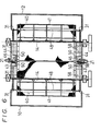
- Figs. 5 to 7 show another embodiment of the present invention.
- the same elements as those in the first embodiment are indicated by the same reference numerals as used in Figs. 3 and 4, and description thereof is omitted in the following.
- the difference between the first embodiment and the second embodiment is that in view of the possibility that the fibre-containing liquid guided with high efficiency may flow into the mass-collecting compartments 46 defined between the adjacent small-diameter end portions 43 and 44 of the cages 40, shield plates 50 are provided disposed one each between the lower end surfaces of the portions of the cages 40 covered with the wire gauzes 41 and the mass-collecting compartments 46, by means of arms 58 fixed to the inner wall surfaces of the tanks 10 and 12.
- each of the shield plates 50 comprises a plastic plate member 52 of low frictional resistance disposed in contact with the lower end surfaces of the portions of the cages 40 covered with the wire gauzes 41 and a metal plate member 54 stationarily superposed on the plastic plate member 52.
- the shield plate 50 may optionally be divided into two segments as illustrated in Figs. 7A and 7B.
- the plastic plate member 52 of the shield plate 50 mounted on the stationary butt 10 side is provided integrally with an extension member 56 which extends in the direction of the tank 12, whereas the plastic plate member 52 of the shield plate 50 mounted on the tank 12 is cut off at the portion thereof corresponding to the extension member 56, so that the metal plate member 54 of the shield plate 50 on the tank 12 can overlap the extension member 56 extending from the stationary tank 10 side at all times even when the tank 12 is swung, thereby enabling the mass-collecting compartments 46 and the lower end surfaces of the portions of the cages 40 covered with the wire gauzes 41 to be continuously shielded completely.
- the fibre-containing liquid efficiently guided by the coaction of the curved lower portions of the tanks 10 and 12 and the inverted U-shaped flexible member 21 for joining the lower edges of the openings is concentrated upon the surfaces of the wire gauzes 41 of the cages 40 without flowing into the mass-collecting compartments 46 due to the presence of the shield plates 50.
- the fibres contained in the liquid are ideally adsorbed on the surfaces of the gauzes 41.
Landscapes
- Engineering & Computer Science (AREA)
- Mechanical Engineering (AREA)
- Paper (AREA)
Applications Claiming Priority (4)
| Application Number | Priority Date | Filing Date | Title |
|---|---|---|---|
| JP122838/83U | 1983-08-09 | ||
| JP12283883U JPS6032398U (ja) | 1983-08-09 | 1983-08-09 | ダブルシリンダ−プレス |
| JP71094/84U | 1984-05-17 | ||
| JP7109484U JPS60185700U (ja) | 1984-05-17 | 1984-05-17 | ダブルシリンダ−プレス |
Publications (2)
| Publication Number | Publication Date |
|---|---|
| EP0136787A1 true EP0136787A1 (fr) | 1985-04-10 |
| EP0136787B1 EP0136787B1 (fr) | 1987-04-29 |
Family
ID=26412224
Family Applications (1)
| Application Number | Title | Priority Date | Filing Date |
|---|---|---|---|
| EP84305340A Expired EP0136787B1 (fr) | 1983-08-09 | 1984-08-06 | Presse à double-cylindre pour la formation de couches de fibres |
Country Status (4)
| Country | Link |
|---|---|
| US (1) | US4543161A (fr) |
| EP (1) | EP0136787B1 (fr) |
| KR (1) | KR880002444Y1 (fr) |
| DE (1) | DE3463342D1 (fr) |
Cited By (3)
| Publication number | Priority date | Publication date | Assignee | Title |
|---|---|---|---|---|
| WO1996006221A3 (fr) * | 1994-08-22 | 1996-04-11 | Ingersoll Rand Co | Tambour de traitement des boues de pate et presses mono et bicylindres en comportant |
| AT405420B (de) * | 1997-05-26 | 1999-08-25 | Andritz Patentverwaltung | Vorrichtung zur entwässerung und wäsche von faserstoffsuspensionen |
| EP2231919A4 (fr) * | 2007-12-13 | 2013-01-16 | Metso Paper Inc | Appareil de lavage et d'épaississement de pâte à papier |
Families Citing this family (7)
| Publication number | Priority date | Publication date | Assignee | Title |
|---|---|---|---|---|
| SE448311B (sv) * | 1986-04-08 | 1987-02-09 | Sunds Defibrator | Avvattningspress |
| US5063840A (en) * | 1990-07-27 | 1991-11-12 | Ingersoll-Rand Company | Pulp press vat providing enhanced bottom access |
| US5213346A (en) * | 1991-08-19 | 1993-05-25 | Ingersoll-Rand Company | Method and apparatus for sealing between two relatively articulable surfaces |
| SE501799C2 (sv) * | 1993-09-15 | 1995-05-15 | Sunds Defibrator Ind Ab | Inlopp vid anordning med samverkande pressvalsar för avvattning av materialsuspensioner såsom massasuspensioner |
| AT401185B (de) * | 1994-10-14 | 1996-07-25 | Andritz Patentverwaltung | Vorrichtung zur entwässerung und bzw. oder wäsche von suspensionen, insbesondere faserstoffsuspensionen |
| SE512753C2 (sv) * | 1999-03-09 | 2000-05-08 | Kvaerner Pulping Tech | Anordning för tvättning och avvattning av en fibermassasuspension. |
| SE9903078L (sv) * | 1999-08-27 | 2000-07-17 | Kvaerner Pulping Tech | Tätningsanordning för tvättpress |
Citations (3)
| Publication number | Priority date | Publication date | Assignee | Title |
|---|---|---|---|---|
| DE1759825A1 (de) * | 1968-06-12 | 1972-03-16 | Fortschritt Veb K | Vorrichtung zur Herstellung von Presslingen |
| GB2025248A (en) * | 1978-06-23 | 1980-01-23 | Danske Sukkerfab | Rotary drum or disc filter |
| US4242204A (en) * | 1979-04-03 | 1980-12-30 | Ake Stigebrandt | Apparatus for separation of material suspended in liquids |
Family Cites Families (6)
| Publication number | Priority date | Publication date | Assignee | Title |
|---|---|---|---|---|
| DE18877C (de) * | A. D. R. DUJARDIN in Lille | Continuirlich wirkende Doppelwalzenpresse für Zuckerfabriken etc | ||
| US3772144A (en) * | 1971-04-14 | 1973-11-13 | Improved Machinery Inc | Apparatus and method for thickening and washing suspensions containing fibrous material |
| US3730079A (en) * | 1971-06-22 | 1973-05-01 | Improved Machinery Inc | Variable nip press having rolls maintained on parallel axes |
| JPS5210741A (en) * | 1975-07-15 | 1977-01-27 | Yokohama Kiko Kk | Manufacturing method of a reflecting mirror |
| SU589315A1 (ru) * | 1976-07-02 | 1978-01-25 | Научно-Исследовательский И Проектно-Конструкторский Институт Целлюлозного Машиностроения | Сгуститель барабанный |
| AU525894B2 (en) * | 1978-03-20 | 1982-12-09 | James Hardie & Coy Pty Limited | Extracting solids from slurry |
-
1984
- 1984-08-06 DE DE8484305340T patent/DE3463342D1/de not_active Expired
- 1984-08-06 EP EP84305340A patent/EP0136787B1/fr not_active Expired
- 1984-08-07 KR KR2019840007688U patent/KR880002444Y1/ko not_active Expired
- 1984-08-08 US US06/638,714 patent/US4543161A/en not_active Expired - Fee Related
Patent Citations (3)
| Publication number | Priority date | Publication date | Assignee | Title |
|---|---|---|---|---|
| DE1759825A1 (de) * | 1968-06-12 | 1972-03-16 | Fortschritt Veb K | Vorrichtung zur Herstellung von Presslingen |
| GB2025248A (en) * | 1978-06-23 | 1980-01-23 | Danske Sukkerfab | Rotary drum or disc filter |
| US4242204A (en) * | 1979-04-03 | 1980-12-30 | Ake Stigebrandt | Apparatus for separation of material suspended in liquids |
Cited By (4)
| Publication number | Priority date | Publication date | Assignee | Title |
|---|---|---|---|---|
| WO1996006221A3 (fr) * | 1994-08-22 | 1996-04-11 | Ingersoll Rand Co | Tambour de traitement des boues de pate et presses mono et bicylindres en comportant |
| US5667642A (en) * | 1994-08-22 | 1997-09-16 | Beloit Technologies, Inc. | Pulp slurry-handling press roll and twin and single roll slurry handling presses |
| AT405420B (de) * | 1997-05-26 | 1999-08-25 | Andritz Patentverwaltung | Vorrichtung zur entwässerung und wäsche von faserstoffsuspensionen |
| EP2231919A4 (fr) * | 2007-12-13 | 2013-01-16 | Metso Paper Inc | Appareil de lavage et d'épaississement de pâte à papier |
Also Published As
| Publication number | Publication date |
|---|---|
| US4543161A (en) | 1985-09-24 |
| DE3463342D1 (en) | 1987-06-04 |
| KR850009529U (ko) | 1985-12-05 |
| KR880002444Y1 (ko) | 1988-07-05 |
| EP0136787B1 (fr) | 1987-04-29 |
Similar Documents
| Publication | Publication Date | Title |
|---|---|---|
| EP0136787B1 (fr) | Presse à double-cylindre pour la formation de couches de fibres | |
| EP0251787B1 (fr) | Appareil pour l'épaississement de la pâte à papier | |
| US4446094A (en) | Apparatus and method for extracting fluid from an extruded material | |
| DE2526657C3 (de) | Drucksichter für Fasersuspensionen | |
| JP4850464B2 (ja) | 夾雑物処理装置 | |
| CN106239962A (zh) | 具有主轴及无轴螺旋部区间的垃圾脱水装置 | |
| EP0369611B1 (fr) | Appareil pour épaissir des suspensions de pâte à papier | |
| JPS61115699A (ja) | スラリ処理方法及び装置 | |
| KR101025020B1 (ko) | 협잡물 처리장치 | |
| JPH10510761A (ja) | 脱水装置 | |
| EP0640716B1 (fr) | Aménagement pour guider une bande fibreuse dans un séchoir | |
| DE20107846U1 (de) | Formersieb | |
| GB2104402A (en) | Apparatus for removing solid material from sewage | |
| WO2009119295A1 (fr) | Séparateur solide-liquide, filtre, et procédé de séparation solide-liquide | |
| CN214654396U (zh) | 污泥处理装置的送料机构 | |
| CA2213352A1 (fr) | Section des presses et procede d'essorrage de feuilles de pate humide | |
| EP0192803B1 (fr) | Sas comprenant une roue à cellules pour séparer de fines particules solides à partir d'un courant d'air | |
| US3775243A (en) | Water saveall for grooved roll in paper machine press nip | |
| JPH0450120B2 (fr) | ||
| FI89388B (fi) | Apparat foer behandling av ett vaetskehaltigt fibermaterial | |
| US6558557B1 (en) | Process and a decker for bringing together two suspension layers | |
| FI76855B (fi) | Filtreringspress. | |
| AT501331B1 (de) | Ausschusssystem für eine papiermaschine oder eine gleichwertige maschine für faserbahnen | |
| JPS586214A (ja) | 脱水機 | |
| KR0133405Y1 (ko) | 폐기물처리장치 |
Legal Events
| Date | Code | Title | Description |
|---|---|---|---|
| PUAI | Public reference made under article 153(3) epc to a published international application that has entered the european phase |
Free format text: ORIGINAL CODE: 0009012 |
|
| AK | Designated contracting states |
Designated state(s): DE FR SE |
|
| 17P | Request for examination filed |
Effective date: 19850924 |
|
| 17Q | First examination report despatched |
Effective date: 19860704 |
|
| GRAA | (expected) grant |
Free format text: ORIGINAL CODE: 0009210 |
|
| AK | Designated contracting states |
Kind code of ref document: B1 Designated state(s): DE FR SE |
|
| REF | Corresponds to: |
Ref document number: 3463342 Country of ref document: DE Date of ref document: 19870604 |
|
| ET | Fr: translation filed | ||
| PLBE | No opposition filed within time limit |
Free format text: ORIGINAL CODE: 0009261 |
|
| STAA | Information on the status of an ep patent application or granted ep patent |
Free format text: STATUS: NO OPPOSITION FILED WITHIN TIME LIMIT |
|
| 26N | No opposition filed | ||
| EAL | Se: european patent in force in sweden |
Ref document number: 84305340.6 |
|
| PGFP | Annual fee paid to national office [announced via postgrant information from national office to epo] |
Ref country code: FR Payment date: 19960809 Year of fee payment: 13 |
|
| PGFP | Annual fee paid to national office [announced via postgrant information from national office to epo] |
Ref country code: DE Payment date: 19960812 Year of fee payment: 13 |
|
| PGFP | Annual fee paid to national office [announced via postgrant information from national office to epo] |
Ref country code: SE Payment date: 19960815 Year of fee payment: 13 |
|
| PG25 | Lapsed in a contracting state [announced via postgrant information from national office to epo] |
Ref country code: SE Free format text: LAPSE BECAUSE OF NON-PAYMENT OF DUE FEES Effective date: 19970807 |
|
| PG25 | Lapsed in a contracting state [announced via postgrant information from national office to epo] |
Ref country code: FR Free format text: LAPSE BECAUSE OF NON-PAYMENT OF DUE FEES Effective date: 19980430 |
|
| PG25 | Lapsed in a contracting state [announced via postgrant information from national office to epo] |
Ref country code: DE Free format text: LAPSE BECAUSE OF NON-PAYMENT OF DUE FEES Effective date: 19980501 |
|
| EUG | Se: european patent has lapsed |
Ref document number: 84305340.6 |
|
| REG | Reference to a national code |
Ref country code: FR Ref legal event code: ST |