EP0137144A2 - Unité de joint - Google Patents
Unité de joint Download PDFInfo
- Publication number
- EP0137144A2 EP0137144A2 EP84108252A EP84108252A EP0137144A2 EP 0137144 A2 EP0137144 A2 EP 0137144A2 EP 84108252 A EP84108252 A EP 84108252A EP 84108252 A EP84108252 A EP 84108252A EP 0137144 A2 EP0137144 A2 EP 0137144A2
- Authority
- EP
- European Patent Office
- Prior art keywords
- seal
- unitized
- unitizing
- piece
- joint
- Prior art date
- Legal status (The legal status is an assumption and is not a legal conclusion. Google has not performed a legal analysis and makes no representation as to the accuracy of the status listed.)
- Granted
Links
Images

Classifications
-
- F—MECHANICAL ENGINEERING; LIGHTING; HEATING; WEAPONS; BLASTING
- F16—ENGINEERING ELEMENTS AND UNITS; GENERAL MEASURES FOR PRODUCING AND MAINTAINING EFFECTIVE FUNCTIONING OF MACHINES OR INSTALLATIONS; THERMAL INSULATION IN GENERAL
- F16J—PISTONS; CYLINDERS; SEALINGS
- F16J15/00—Sealings
- F16J15/16—Sealings between relatively-moving surfaces
- F16J15/32—Sealings between relatively-moving surfaces with elastic sealings, e.g. O-rings
- F16J15/3248—Sealings between relatively-moving surfaces with elastic sealings, e.g. O-rings provided with casings or supports
- F16J15/3252—Sealings between relatively-moving surfaces with elastic sealings, e.g. O-rings provided with casings or supports with rigid casings or supports
- F16J15/3256—Sealings between relatively-moving surfaces with elastic sealings, e.g. O-rings provided with casings or supports with rigid casings or supports comprising two casing or support elements, one attached to each surface, e.g. cartridge or cassette seals
-
- F—MECHANICAL ENGINEERING; LIGHTING; HEATING; WEAPONS; BLASTING
- F16—ENGINEERING ELEMENTS AND UNITS; GENERAL MEASURES FOR PRODUCING AND MAINTAINING EFFECTIVE FUNCTIONING OF MACHINES OR INSTALLATIONS; THERMAL INSULATION IN GENERAL
- F16C—SHAFTS; FLEXIBLE SHAFTS; ELEMENTS OR CRANKSHAFT MECHANISMS; ROTARY BODIES OTHER THAN GEARING ELEMENTS; BEARINGS
- F16C19/00—Bearings with rolling contact, for exclusively rotary movement
- F16C19/22—Bearings with rolling contact, for exclusively rotary movement with bearing rollers essentially of the same size in one or more circular rows, e.g. needle bearings
- F16C19/34—Bearings with rolling contact, for exclusively rotary movement with bearing rollers essentially of the same size in one or more circular rows, e.g. needle bearings for both radial and axial load
-
- F—MECHANICAL ENGINEERING; LIGHTING; HEATING; WEAPONS; BLASTING
- F16—ENGINEERING ELEMENTS AND UNITS; GENERAL MEASURES FOR PRODUCING AND MAINTAINING EFFECTIVE FUNCTIONING OF MACHINES OR INSTALLATIONS; THERMAL INSULATION IN GENERAL
- F16C—SHAFTS; FLEXIBLE SHAFTS; ELEMENTS OR CRANKSHAFT MECHANISMS; ROTARY BODIES OTHER THAN GEARING ELEMENTS; BEARINGS
- F16C33/00—Parts of bearings; Special methods for making bearings or parts thereof
- F16C33/72—Sealings
- F16C33/76—Sealings of ball or roller bearings
Definitions
- the present invention relates to unitized seals generally, and more particularly to a novel unitized seal structure designed to reduce the possibility of damage to the sealing lip during either assembly or installation of the unitized seal.
- Some prior art unitized seals incorporate a unitized structure wherein the wear sleeve members are formed from a plurality of nested parts which are locked together. These seal units have tended to leak in the area between the nested metal members and have often required the use of additional gasket material to reduce such leakage. Attempts have been made to design more reliable unitized seals having wear sleeves formed from nested parts which do not require additional gasket material as illustrated by U.S. Patent Nos. 3,275,333 to A . M . Scott et al and 3,479,728 to P.C. Burfield et al.
- seal designs do effectively reduce the expense previously incurred in providing gaskets between the wear sleeve sections of.a multi-part unitized seal, but such seals still require additional expense for the formation of the plurality of seal parts used in the assembly. These parts must be individually stamped or molded, and often three or more stamped components and a plurality of molding operations are necessitated for the formation of a single unitized seal.
- the seal structure is such that the seal is easily damaged during assembly or disassembly.
- the unitizing joint for the seal is located in close proximity to the elastomeric seal lip, thereby exposing the seal lip to possible damage by contact with the seal unitizing joint during seal assembly or disassembly.
- U.S. Patent No. 3,022,081 to T.O. Kostaka illustrates a unitized seal which may be easily disassembled by deflecting the rubber seal element.
- the seal element might become exposed to sharp metal edges of metal seal components during this disassembly operation, and damage to the seal contact surface is thereby possible, and in the case of lined seals, likely. Consequently, a need has arisen for the development of a simple, inexpensive unitized seal structure designed to reduce the possibility of damage to a sealing lip during either assembly, disassembly or installation of the seal.
- the seal includes a one-piece wear sleeve having a cylindrical hub with a wear surface on that hub and an annular deflector ring extending radially outwardly from the hub wear surface.
- a one-piece reinforcing shell has a one-piece elastomeric element bonded thereto, and the elastomeric element includes the seal lip contacting the wear surface of the wear sleeve.
- the reinforcing shell includes a tail portion which forms a unitizing joint flange when rolled over, and this tail portion, which is positioned to be remote from the elastomeric seal lip, is adapted to cooperate with an outer circumferential portion of the annular deflector ring to form a unitizing joint for the seal.
- the unitizing joint and the elastomeric seal lip are widely separated and remote from each other, and the elastomeric seal lip is not encapsulated by the wear sleeve except in the embodiment of Figure 5.
- a further object of the present invention is to provide a novel and improved unitized seal for a wheel assembly which permits inner and outer bearings of the wheel assembly to be removed without disturbing the unitized seal, except in the embodiment shown in Figure 5 hereof.
- the unitized seal includes a one-piece elastomeric element which has a seal lip engaging a wear sleeve wear surface and elastomeric beads for engaging the bore of a hub of the wheel assembly.
- the wear sleeve is metal and is press fit to an axle in a manner such that less force is required to remove the beads from the hub housing than is required to remove the wear sleeve from the axle. Thus, when the wheel hub housing is removed, the unitized seal will remain in place on the axle.
- Another object of the present invention is to provide a novel and improved unitized seal which includes a seal wear sleeve having a wear surface which can be contolled to reduce the effects of wear and seal irregularity on seal reliability and longevity.
- Still another object of the present invention is to provide a novel and improved unitized seal in which an elastomeric element can be replaced without the use of special tools and without disturbing a wear sleeve for the seal.
- the unitized seal includes a snap ring in a seal unitizing joint, and with the snap ring removed, the elastomeric element can be separated from the wear sleeve and both elements may be examined and reused or replaced as appropriate.
- a still further object of the present invention is to provide a novel and improved unitized seal which can be used in either oil or grease and includes a deflector ring to protect the seal from the ingress of contaminants. Fluid passages can be defined in the deflector ring if suitable.
- a unitized seal which includes a one-piece wear sleeve having a cylindrical hub affixed, as by a press fit, to an axle of a wheel assembly and an annular deflector ring extending radially from the sleeve cylindrical hub.
- the portion of the deflector ring closest to the rim of the deflector ring forms one part of a seal unitizing joint.
- the seal further includes a one-piece elastomeric element bonded to a one-piece reinforcing shell, and the elastomeric element has a seal lip sliding against the wear sleeve wear surface and ridges or beads engaging a hub housing.
- the reinforcing shell includes a tail portion on the end thereof which is remote from the elastomeric sealing lip located at the other end of the reinforcing shell.
- the reinforcing shell tail portion is located adjacent to the rim to form the unitizing joint with an outer peripheral portion of the deflector ring. The seal lip and the unitizing joint are thus remotely located with respect to each other.
- Figure 1 discloses a wheel assembly indicated generally at 8 having a unitized seal 10 located between an axle 12 and a rotating hub housing 14 to prevent oil leakage from the wheel assembly.
- the hub housing is rotatably mounted on the axle by bearing assemblies 16, one of which is shown in Figure 1, and includes a bearing 18 mounted in conventional bearing races 20 and 22.
- the unitized seal 10 requires only two stampings and one elastomeric element.
- a first stamping provides a one-piece wear sleeve 32 having a cylindrical hub section 34 press fit onto the axle 12.
- the wear sleeve 32 includes an annular deflector ring 36 extending radially outwardly from the sleeve hub section 34.
- the second stamping forms a one-piece reinforcing shell 38 having a one-piece elastomeric element 40 bonded thereto.
- the elastomeric element 40 includes circumferential projecting beads or ridges 42 abutting a surface 44 of the hub housing 14 for holding the seal 10 in place, and seal lips 46 and 48 engaging a wear surface 50 on the sleeve cylindrical hub 34.
- the wear sleeve 32 is press fit onto axle 12 and can include press fit defining means and slip fit defining means of various types.
- the press fit between the wear sleeve 32 and the axle 12 is designed to affix the wear sleeve to the axle with greater force than the fit established between the bumpers 42 and the hub housing surface 44. Consequently, the hub housing 14 can be removed from the outer portion of the unitized seal 10 while leaving the unitized seal assembled and in place on the axle 12.
- the seal 10 remains properly positioned for reuse upon reassembly of the hub housiqg 14 and the wheel of the wheel assembly 8.
- the annular deflector ring 36 at the opposite end of the hub 34 acts to deflect external contaminants.
- This deflector ring includes an upright retaining wall 60 connected to the sleeve cylindrical hub 34 by a curved knee section 62. Rings or bumpers 64 formed on the elastomeric element 40 abut the retaining wall 60 to maintain the elements of seal 10 properly positioned and oriented during installation and act as a bearing to prevent seizure caused by metal to metal contact.
- a unitizing joint 70 is formed by a unitizing joint rollover portion 72 provided on one end of shell 38 to cooperate with an outer peripheral surface portion 74 of the retaining wall 60.
- the joint rollover portion 72 is originally a tail portion 72a of the reinforcing shell, and becomes the unitizing joint rollover portion 72 when rolled over into the position shown therefor in Figure 1.
- the joint rollover portion 72 and the peripheral surface portion 74 are located adjacent the upper end of the annular deflector ring, so that the unitizing joint 70 is located remotely from the seal lips 46 and 48.
- rolling over the reinforcing shell tail portion to form unitizing joint rollover portion 72 of the unitizing joint 70 is easily done during manufacture.
- the shell element 38 is a unitary stamping and includes a U-shaped portion formed by a leg 80 connected to a leg 82 by a web portion 84.
- a leg 90 extends radially inwardly from the free end of the leg' 82.
- the elastomeric element 40 is molded on the shell 38 to extend along both sides and over the end of the leg 90 and along surfaces of the legs 80 and 82 and the web 84.
- the one piece shell 38 both supports and reinforces the elastomeric element 40 while forming a portion of the unitizing joint 70.
- the seal lip 46 which is the primary sealing lip and is biased by a garter spring 92, is positioned on one axial side of the leg 90, while the seal lip 48, which is an auxiliary dirt lip, is positioned on the opposite axial side of the leg 90.
- the seal lip 46 may be biased by a conventional finger spring instead of the garter spring 92 in a manner known in the art.
- the unitizing joint rollover portion 72a is formed originally as a thinned end portion of the leg 80, and when curled or crimped as shown at 72 in Figure 1, forms a barrier to prevent the disassembly of the wear sleeve 32 and the shell 38.
- the hub housing 14 may be removed from around the outer portion of the unitized seal 10 by withdrawing it to the right in Figure 1, but the rollover portion 72 will engage surface 74, and the unitized seal will remain assembled in proper position for reuse on the axle 12. Since the unitizing joint 70 is remote from the seal lips 46 and 48, it is not possible for elements of this unitizing joint to contact and damage the seal lips during the withdrawal or repositioning of the hub housing.
- the unitized seal 10 of Figure 1 has been modified so that the rollover portion 72 does not contact surface 74 on the retaining wall 60, but instead is formed to pass freely over the end of the retaining wall.
- a split type retaining ring 130 is removably mounted in a circular groove 132 formed at the juncture between the inner surfaces of the unitizing rollover portion 72 and the leg 80 of the shell 38. This retaining ring extends beyond or past the end of the retaining wall 60 and will contact the surface 74 thereof to maintain the unitized seal 10 assembled and in position on the axle 12..
- the hub housing 14 when the hub housing 14 is removed, it is often desirable to inspect the wear sleeve 32 and the elastomeric element 40 for wear or damage. This may be easily accomplished by removing the split type retaining ring 130 and separating the shell element 38 and elastomeric element 40 from the wear sleeve 32. The elastomeric element or wear sleeve can then be inspected and replaced if wear or damage is discovered, and the seal 10 can be reassembled and the split type ring 130 replaced to return the seal to a unitized configuration.
- Figures 3-8 disclose modifications of the basic unitary seal 10 of Figure 1, and like elements in these figures will be designated with the reference numerals used in Figure 1.
- the unitary seals illustrated in Figures 3-8 all incorporate the basic novel structural features described in connection with the unitary seal of Figure 1; namely, a first stamping which forms a wear sleeve 32, a second stamping which forms a one-piece shell 38, an elastomeric element 40 which is bonded in a single molding operation to the one-piece shell, and a unitizing joint 70 which is positioned remotely from the seal lip(s).
- the unitized seal 138 of Figure 3 is a spindle installed unitized seal, and the annular deflector ring 36 includes an end section 140 bearing the outer peripheral surface portion 74.
- the end section 140 is substantially parallel to the retaining wall 60 and is offset therefrom, by a web section 142 so as to be substantially perpendicular to the wear surface 50, and the unitizing joint 70 is thus spaced axially from the outermost surface of the retaining wall.
- the elastomeric element 40 of the unitized seal 138 does not include the seal lips 46 and 48, but instead has a single seal lip 150 engaging the wear surface 50 of the wear sleeve 32.
- This seal lip is provided with a liner 151 of low friction resin material such as polytetrafluroethylene.
- a unitized seal 152 is shown in Figure 4 which may be installed upon the wheel assembly 8 of Figure 1 without the aid of special installation tooling.
- This unitized seal includes a wear sleeve 32 having. a cylindrical sleeve hub 34 with an annular flange 154 on one end of the sleeve hub opposite to the annular deflector ring 36.
- the flange 154 can be sandwiched. between the end of the axle 12 and the bearing race 22 to maintain the sleeve 32 properly positioned and oriented during installation .
- Press fit defining means and slip fit defining means can also be used in conjunction with the sleeve 32 as indicated in connection with the unitized seal 10,and as illustrated and subsequently described in connection with Figure 6.
- the press fit can be established to keep the seal 152 intact upon removal of the hub housing 14 from the axle.
- the deflector ring 36 includes the sections 140 and 142 as shown in Figure 3 with section 140 forming a seat for a friction modifying material 156.
- the unitizing joint 70 formed for seal 152 thus includes friction modifying material 156 therein. This additional material 156 allows the seal to be installed either on the axle or in the bore first by providing a means to reposition a seal after being placed too deep into a bore.
- the elastomeric element 40 for the unitized,seal 152 includes a seal lip 46 of the type described in connection with the unitized seal 10 of Figures 2 and 2.
- a dust seal lip 48 is also provided.
- a unitized seal 158 which can be installed in a wheel assembly having a hub which rotates with respect to a fixed axle.
- the unitized seal is not affected by centrifugal forces when installed on a rotating hub, and includes a one-piece wear sleeve 32 having a cylindrical hub 34 and an annular deflector ring 36 on one end of the sleeve hub 34.
- the deflector ring 36 includes the retaining wall 60 which forms a web between radially inner and outer axially extending parallel legs 160 and 162 respectively.
- the terminal end 164 of leg 160 cooperates with unitizing joint rollover portion 72 to form the unitizing joint 70.
- Leg 162 is connected by a wall section 166 to an axially extending wall section 168.
- Wall section 166 extends substantially parallel to the retaining wall 60
- wall section 168 extends substantially parallel to the legs 160 and 162 and is connected to the cylindrical hub 34 by knee section 62.
- leg 162 and wall sections 166 and 168 cooperate with knee section 62 and cylindrical sleeve hub 34 to form a chamber 170 into which the seal lip 46 of the elastomeric element 40 extends.
- the wear sleeve 32 is reversed in the unitized seal 158 from the position shown therefor in the previous figures.
- the sleeve hub section is press fit into the hub while elastomeric beads 165 are provided to engage the axle.
- Oil vents, such as that illustrated in dotted lines at 172 may be located to extend into the chamber 170 anywhere on the leg 162, the wall sections 166 or 168, or the knee section 62.
- a unitized seal 174 is illustrated wherein the wear sleeve 32 is provided with a press fit defining unit 176 bonded to the surface thereof opposite to wear surface 50.
- This press fit defining unit may constitute a molded, elastomeric unit having annular ridges or beads 178 projecting therefrom to engage the axle of a wheel assembly. These beads are designed to grip the axle with a greater retaining force than that applied to the hub housing by the beads 42 of the elastomeric element 40.
- the unitized seal 174 is designed to be installed by hand on the wheel assembly and thus the shell 38 is shaped to enhance such installation.
- the web 84 between the legs 80 and 82 of the unitized seal 10 of Figure 1 is substantially eliminated and the length of the leg 80 is extended to bottom out in the bore causing the sleeve 32 to be positioned by contact with beads 64.
- the leg 82 is joined to the leg 80 by a curved section 180, and this permits the ridges or beads 42 on the elastomeric element 40 to be offset when desired to the right in Figure 6 behind the leading beads 178 of the press fit defining unit 176.
- a flat leading edge 182 of the press fit defining unit forms an initial fit with the axle 12 so that the unitized seal is properly started on the axle. Then the wear sleeve 32 can be press fit onto the axle 12 and the hub housing fit over the beads 42.
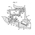
- a unitized seal 184 is shown in Figure 7 which incorporates features of the unitized seals 152 and 174 of Figures 4 and 6 respectively and which may be installed without special installation tooling.
- the cylindrical hub 34 of the wear sleeve 32 includes the flange 154 of the unitized seal 152 which is sandwiched between a shoulder 186 formed on the axle 12 and the bearing race 22. This assures the accurate orientation and positioning of the unitized seal during assembly thereof with the wheel assembly 8.
- the one piece shell 38 described in connection with the unitized seal 174 is employed.
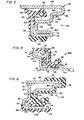
- Figure 8 discloses a unitized seal 188 designed for a fixed bore and rotating shaft which varies somewhat in structural configuration from thç unitized seals heretofore described but which still incorporates the novel structural concept embodied in those unitized seals; namely, first and second stampings forming a wear sleeve 32 and a shell 38 respectively, an elastomeric element 40 bonded to the shell in a single molding step, and a unitizing joint 70 positioned so as to be remote from the seal lips formed on the elastomeric element.
- the wear sleeve 32 includes a retaining wall 60 which extends outwardly from one end of the cylindrical hub 34 in a plane substantially perpendicular to that of the wear surface 50.
- a flange section 190 angles outwardly away from the retaining wall toward the leg 80 of the shell 38. The end 192 of this flange section cooperates with the unitizing joint rollover portion 72 to form the unitizing joint 70.
- the one piece shell 38 of the unitized seal 188 includes only the legs 80 and 90 connected in an "L" shaped configuration.
- the elastomeric element 40 is molded and bonded to the surfaces of the shell 38.
- the unitized seals of the present invention are adapted for use in many applications although the seals have been shown herein primarily on wheel assemblies and spindles.
- the seals. operate to provide.an effective fluid sealing action between a first element, such as an axle or shaft, and a second element such as a wheel hub spaced therefrom, such elements being relatively rotatable.
- the seals are designed to grip the first element with a force greater than that applied by the seal to the second element so that the second element can be withdrawn leaving the seal intact and in position on the first element.
Landscapes
- Engineering & Computer Science (AREA)
- General Engineering & Computer Science (AREA)
- Mechanical Engineering (AREA)
- Sealing With Elastic Sealing Lips (AREA)
- Glass Compositions (AREA)
- Sealing Of Bearings (AREA)
- Electrical Discharge Machining, Electrochemical Machining, And Combined Machining (AREA)
Priority Applications (1)
| Application Number | Priority Date | Filing Date | Title |
|---|---|---|---|
| AT84108252T ATE50845T1 (de) | 1983-08-25 | 1984-07-13 | Dichtungseinheit. |
Applications Claiming Priority (2)
| Application Number | Priority Date | Filing Date | Title |
|---|---|---|---|
| US06/526,285 US5004248A (en) | 1983-08-25 | 1983-08-25 | Unitized seal with unitizing joint remote from seal lip |
| US526285 | 1983-08-25 |
Publications (3)
| Publication Number | Publication Date |
|---|---|
| EP0137144A2 true EP0137144A2 (fr) | 1985-04-17 |
| EP0137144A3 EP0137144A3 (en) | 1986-08-06 |
| EP0137144B1 EP0137144B1 (fr) | 1990-03-07 |
Family
ID=24096699
Family Applications (1)
| Application Number | Title | Priority Date | Filing Date |
|---|---|---|---|
| EP84108252A Expired - Lifetime EP0137144B1 (fr) | 1983-08-25 | 1984-07-13 | Unité de joint |
Country Status (6)
| Country | Link |
|---|---|
| US (1) | US5004248A (fr) |
| EP (1) | EP0137144B1 (fr) |
| JP (1) | JPS6060373A (fr) |
| AT (1) | ATE50845T1 (fr) |
| CA (1) | CA1261894A (fr) |
| DE (1) | DE3481541D1 (fr) |
Cited By (6)
| Publication number | Priority date | Publication date | Assignee | Title |
|---|---|---|---|---|
| GB2212569A (en) * | 1987-11-16 | 1989-07-26 | Rubery Owen Rockwell Ltd | Seal assemblies |
| EP0337321A3 (en) * | 1988-04-12 | 1990-02-07 | Riv-Skf Officine Di Villar Perosa S.P.A | An improved sealing assembly of the double screen type and rolling element bearing provided with such sealing assembly |
| GB2235956A (en) * | 1989-08-04 | 1991-03-20 | Dowty Woodville Polymer Ltd | Unitised seal assembly |
| EP0454193A1 (fr) * | 1990-04-27 | 1991-10-30 | Forsheda AB | Dispositif d'étanchéité pour étancher une espace annulaire entre deux organes de machine tournant l'une contre l'autre |
| AU619844B2 (en) * | 1984-03-30 | 1992-02-06 | Chicago Rawhide Manufacturing Company | Unitized seals and methods |
| CN114635915A (zh) * | 2015-06-12 | 2022-06-17 | Nok株式会社 | 密封装置 |
Families Citing this family (83)
| Publication number | Priority date | Publication date | Assignee | Title |
|---|---|---|---|---|
| US4531748A (en) * | 1984-03-30 | 1985-07-30 | Chicago Rawhide Manufacturing Co. | Fluid seal with unitary wear sleeve element |
| JPS62283261A (ja) * | 1986-05-29 | 1987-12-09 | Uchiyama Mfg Corp | 組合せシ−ル |
| JPH0171271U (fr) * | 1987-10-30 | 1989-05-12 | ||
| JPH0686908B2 (ja) * | 1987-11-23 | 1994-11-02 | ザ ティムケン カンパニー | 封止面とシールとの組み合わせ |
| JPH0641020Y2 (ja) * | 1988-08-19 | 1994-10-26 | エヌオーケー株式会社 | ユニタイズドシール |
| JPH089491Y2 (ja) * | 1988-10-25 | 1996-03-21 | エヌオーケー株式会社 | スリーブ付一体型密封装置 |
| JPH073089Y2 (ja) * | 1988-12-23 | 1995-01-30 | エヌオーケー株式会社 | 密封装置 |
| WO1993017263A1 (fr) * | 1990-02-16 | 1993-09-02 | Stephen Raymond Heinzen | Joint d'etancheite |
| IT1252112B (it) * | 1990-07-25 | 1995-06-05 | Zahnradfabrik Friedrichshafen | Disposizione di guarnizioni del tipo costruttivo a cassetta |
| US5183269A (en) * | 1991-02-06 | 1993-02-02 | Chicago Rawhide Manufacturing Co. | Unitized grit seal with removable thrust bumper |
| DE4110154C2 (de) * | 1991-03-27 | 1996-08-29 | Bruss Dichtungstechnik | Wellendichtring |
| US5186472A (en) * | 1991-06-25 | 1993-02-16 | Federal-Mogul Corporation | Unitized radial shaft seal |
| US5326111A (en) * | 1991-07-19 | 1994-07-05 | Mather Seal Company | Separately bonded elastomeric sleeve for seal casing |
| DE4125183C2 (de) * | 1991-07-30 | 1993-11-25 | Freudenberg Carl Fa | Kassettendichtung |
| JPH0555438A (ja) * | 1991-08-26 | 1993-03-05 | Rohm Co Ltd | 電子部品のリード端子構造 |
| US5398942A (en) * | 1992-09-02 | 1995-03-21 | Dana Corporation | Annular lubricant seal assembly |
| US5292199A (en) * | 1993-05-07 | 1994-03-08 | Ford Motor Company | Axle wheel seal and bearing arrangement for a motor vehicle |
| US6065755A (en) * | 1993-05-21 | 2000-05-23 | Jm Clipper Corporation | Seal device |
| US5887875A (en) * | 1994-10-03 | 1999-03-30 | Ford Global Technologies, Inc. | Unitary axle seal for a motor vehicle |
| US5553866A (en) * | 1994-11-30 | 1996-09-10 | Freudenberg-Nok General Partnership | Cartridge-type lip seal with removable spacer |
| DE19518577C2 (de) * | 1995-05-20 | 1998-07-09 | Freudenberg Carl Fa | Radialwellendichtring |
| JP3581969B2 (ja) * | 1995-06-16 | 2004-10-27 | Nok株式会社 | 密封装置 |
| US5895051A (en) * | 1997-07-16 | 1999-04-20 | Freudenberg-Nok General Partnership | Noise abating beads on a rack seal |
| US6186507B1 (en) | 1997-09-25 | 2001-02-13 | Michael R. Oldenburg | Retrofittable severe duty seal for a shaft |
| US20020011710A1 (en) * | 1997-09-25 | 2002-01-31 | Oldenburg Michael R. | Retrofittable severe duty seal for a shaft |
| US5997005A (en) * | 1997-10-24 | 1999-12-07 | Stemco Inc | Hub seal with machinable thrust ring |
| EP1016799A3 (fr) * | 1998-12-28 | 2001-02-28 | Firma Carl Freudenberg | Cartouche d'étanchéité pour un palier d'arbre |
| EP1016800B1 (fr) * | 1998-12-28 | 2002-12-11 | Carl Freudenberg KG | Cartouche d'étanchéité pour un palier d'arbre |
| US6220600B1 (en) * | 1999-10-07 | 2001-04-24 | Federal-Mogul World Wide, Inc. | Low installation/removal force wear sleeve and method of use |
| JP4719977B2 (ja) * | 2001-01-09 | 2011-07-06 | 日本精工株式会社 | 転がり軸受用密封装置とその搬送方法並びに組み付け方法 |
| JP2002227858A (ja) * | 2001-01-31 | 2002-08-14 | Koyo Seiko Co Ltd | 車軸用軸受の密封装置 |
| JP4685248B2 (ja) * | 2001-02-05 | 2011-05-18 | 光洋シーリングテクノ株式会社 | オイルシール |
| US6692007B2 (en) | 2001-10-31 | 2004-02-17 | Transcom, Inc. | Seal for a shaft |
| US6845986B2 (en) | 2002-04-26 | 2005-01-25 | Stemco Llc | Low torque seal assembly |
| US6722657B2 (en) | 2002-05-31 | 2004-04-20 | Stemco Llc | Low torque seal assembly with open cell filter media |
| DE10235079A1 (de) * | 2002-07-31 | 2004-02-19 | Carl Freudenberg Kg | Manschettendichtung |
| DE20212758U1 (de) * | 2002-08-20 | 2004-01-08 | Dichtungstechnik G. Bruss Gmbh & Co. Kg | Vormontierbare Kassettendichtung mit integrierter Lauffläche |
| US6726210B2 (en) * | 2002-09-25 | 2004-04-27 | Li Ming Machinery Industrial Co., Ltd. | Sealing device for a gear box |
| US8820751B2 (en) | 2004-07-12 | 2014-09-02 | Aktiebolaget Skf | Seal with plastic inner cup |
| US8196933B2 (en) * | 2004-07-12 | 2012-06-12 | Skf Usa Inc. | Seal with plastic inner cup |
| CN101080591B (zh) * | 2004-12-20 | 2010-10-06 | 伊格尔工业股份有限公司 | 轴封装置 |
| US7854432B2 (en) * | 2005-02-24 | 2010-12-21 | Freudenberg-Nok General Partnership | Dynamic seal |
| US7854433B2 (en) * | 2005-02-24 | 2010-12-21 | Freudenberg-Nok General Partnership | Dynamic seal |
| ITTO20050172A1 (it) * | 2005-03-16 | 2006-09-17 | Rft Spa | Gruppo preassemblabile perfezionato con un dispositivo di tenuta da montare nel mozzo della ruota di un automezzo pesante ed un componente per il montaggio e lo smontaggio di tale dispositivo. |
| US20070007731A1 (en) * | 2005-07-11 | 2007-01-11 | Zahn Henry W | Double lip dust excluder fork seal |
| US20070182105A1 (en) * | 2006-01-26 | 2007-08-09 | Garlock Sealing Technologies, Llc. A Delaware Corporation | Seal configuration |
| US8925927B2 (en) | 2006-02-10 | 2015-01-06 | Freudenberg-Nok General Partnership | Seal with controllable pump rate |
| US8376369B2 (en) * | 2006-02-10 | 2013-02-19 | Freudenberg-Nok General Partnership | Seal with spiral grooves and contamination entrapment dams |
| US7775528B2 (en) | 2006-02-13 | 2010-08-17 | Freudenberg-Nok General Partnership | Bi-directional pattern for dynamic seals |
| EP2044351B1 (fr) * | 2006-07-20 | 2012-12-26 | Carl Freudenberg KG | Procédé de fabrication d'un joint d'étanchéité |
| US8052152B2 (en) * | 2007-03-09 | 2011-11-08 | Federal-Mogul Corporation | Dynamic shaft seal and method of installation thereof |
| US8628250B2 (en) * | 2007-05-25 | 2014-01-14 | Hitchi, Ltd. | Support device for supporting propeller shaft and propeller shaft itself |
| US8342535B2 (en) * | 2007-11-20 | 2013-01-01 | The Timken Company | Non-contact labyrinth seal assembly and method of construction thereof |
| US8991829B2 (en) | 2007-11-20 | 2015-03-31 | The Timken Company | Non-contact labyrinth seal assembly and method of construction thereof |
| JPWO2009130933A1 (ja) * | 2008-04-25 | 2011-08-11 | Nok株式会社 | 密封装置 |
| US8214987B1 (en) | 2008-10-14 | 2012-07-10 | Jefferson Science Associates, Llc | Remote vacuum or pressure sealing device and method for critical isolated systems |
| US8590903B2 (en) | 2009-03-24 | 2013-11-26 | Freudenberg-Nok General Partnership | Lip seal with inversion prevention feature |
| US20100270751A1 (en) * | 2009-04-23 | 2010-10-28 | Gm Global Technology Operations, Inc. | Anti-roll ribbed seal |
| US8454025B2 (en) * | 2010-02-24 | 2013-06-04 | Freudenberg-Nok General Partnership | Seal with spiral grooves and mid-lip band |
| US8439363B2 (en) | 2010-09-20 | 2013-05-14 | Federal-Mogul Corporation | Dynamic radial shaft seal assembly with combination dust exclusion thrust pad |
| JP2012202474A (ja) * | 2011-03-25 | 2012-10-22 | Jtekt Corp | 転がり軸受の密封装置 |
| US9958011B2 (en) | 2011-04-01 | 2018-05-01 | Roller Bearing Company Of America, Inc. | Bearing assembly having surface protrusions and a seal |
| US9316257B2 (en) | 2011-04-01 | 2016-04-19 | Roller Bearing Company Of America, Inc. | Spherical bearing with sealing member member |
| US9845883B2 (en) * | 2011-06-09 | 2017-12-19 | Federal-Mogul Llc | Shaft seal assembly |
| US8783953B2 (en) | 2011-07-21 | 2014-07-22 | Roller Bearing Company Of America, Inc. | Low friction seal for bearings |
| US8657296B1 (en) | 2011-10-26 | 2014-02-25 | Engineered Seal Products, Inc. | Radial shaft seal |
| US8919782B2 (en) | 2012-10-19 | 2014-12-30 | Freudenberg-Nok General Partnership | Dynamic lay down lip seal with bidirectional pumping feature |
| JP5971617B2 (ja) * | 2012-10-25 | 2016-08-17 | Nok株式会社 | ボールジョイント用ダストカバー |
| US8864139B2 (en) | 2013-03-04 | 2014-10-21 | Federal-Mogul Corporation | Non-contact labyrinth seal assembly |
| US20150001804A1 (en) * | 2013-06-27 | 2015-01-01 | Aktiebolaget Skf | Fluid seal assembly with wear ring |
| US9759330B2 (en) | 2014-02-04 | 2017-09-12 | Freudenberg-Nok General Partnership | Energy saving seal with rocking dust lip |
| US9695937B2 (en) | 2014-02-04 | 2017-07-04 | Freudenberg-Nok General Partnership | Energy saving seal with vacuum induced counter-balance and rocking feature |
| US9714710B2 (en) | 2014-02-04 | 2017-07-25 | Freudenberg-Nok General Partnership | Energy saving self-contact seal with pushing bead |
| US9562567B2 (en) | 2014-02-07 | 2017-02-07 | Roller Bearing Company Of America, Inc. | Spherical bearing with axially compressed annular seal |
| EP3222891B1 (fr) * | 2014-11-18 | 2020-07-29 | Nok Corporation | Structure d'étanchéité |
| TWI603860B (zh) * | 2017-02-24 | 2017-11-01 | 輪轂油封 | |
| IT201700097823A1 (it) * | 2017-08-31 | 2019-03-03 | Skf Ab | Complesso di tenuta a basso attrito, sistema di accoppiamento con un anello di cuscinetto e unita’ mozzo ruota equipaggiata con tale complesso di tenuta |
| DE102017131059A1 (de) | 2017-12-22 | 2019-06-27 | Christiane Kappert | Physiologisch verträgliche Lösung mit einem Gehalt an Pyruvat und Glycin, eine Pyruvat und Glycin enthaltende Zusammensetzung und Verfahren zu deren Herstellung |
| US10907689B2 (en) | 2018-06-21 | 2021-02-02 | Freudenberg-Nok General Partnership | Heavy duty wheel seal with dry running resistance |
| DE102018220346A1 (de) * | 2018-11-27 | 2020-05-28 | Aktiebolaget Skf | Lagerdichtung |
| EP3967896B1 (fr) * | 2019-05-08 | 2025-09-10 | NOK Corporation | Dispositif d'étanchéité |
| US12281703B1 (en) * | 2024-01-10 | 2025-04-22 | Freudenberg-Nok General Partnership | Outboard drive axle hub seal with venting |
| US20250282176A1 (en) * | 2024-03-06 | 2025-09-11 | Dale Robert Booms | Modified bidirectional cassette seals useful in wheel assemblies |
Family Cites Families (25)
| Publication number | Priority date | Publication date | Assignee | Title |
|---|---|---|---|---|
| GB590874A (en) * | 1945-04-25 | 1947-07-30 | Angus George Co Ltd | Improvements relating to oil seals |
| US2089462A (en) * | 1934-03-29 | 1937-08-10 | John R Winter | Grease seal |
| US2804324A (en) * | 1953-09-11 | 1957-08-27 | Gen Motors Corp | Seal |
| US3022081A (en) * | 1957-08-01 | 1962-02-20 | Victor Mfg & Gasket Co | Self-contained fluid seal |
| US3021161A (en) * | 1959-09-14 | 1962-02-13 | Federal Mogul Bower Bearings | Unitized shaft seal |
| US3099454A (en) * | 1961-05-05 | 1963-07-30 | Victor Mfg & Gasket Co | Fluid seal |
| US3275333A (en) * | 1963-08-02 | 1966-09-27 | Federal Mogul Corp | Dual lip unitized seal |
| GB1034756A (en) * | 1965-03-12 | 1966-07-06 | Federal Mogul Bower Bearings | Improved unitized seal |
| US3363911A (en) * | 1965-08-31 | 1968-01-16 | Chicago Rawhide Mfg Co | Shaft seal |
| US3341264A (en) * | 1965-09-03 | 1967-09-12 | Timken Roller Bearing Co | Unitized dual lip seal |
| US3510138A (en) * | 1965-10-15 | 1970-05-05 | Federal Mogul Corp | Oil seal with rock shield and wear sleeve |
| US3495843A (en) * | 1967-04-17 | 1970-02-17 | Chicago Rawhide Mfg Co | Pressure seal with antiextrusion means |
| US3479728A (en) * | 1968-11-18 | 1969-11-25 | Federal Mogul Corp | Method of making a unitized seal |
| US3682488A (en) * | 1969-09-10 | 1972-08-08 | Nippon Oil Seal Ind Co Ltd | Sealing device |
| US4037849A (en) * | 1976-02-11 | 1977-07-26 | The Mechanex Corporation | Lubricant seal |
| US4336945A (en) * | 1977-03-18 | 1982-06-29 | Cr Industries | Sinuous seal with auxiliary excluder lips |
| JPS54107755A (en) * | 1978-02-13 | 1979-08-23 | Canon Inc | Image display device |
| JPS6013718B2 (ja) * | 1978-04-11 | 1985-04-09 | 松下電器産業株式会社 | 脱水洗濯機 |
| IT1108623B (it) * | 1978-07-07 | 1985-12-09 | Iao Industrie Riunite Spa | Dispositivo di tenuta per alberi rotanti |
| US4258927A (en) * | 1978-12-13 | 1981-03-31 | Garlock Inc. | Shaft seal with retractable polytetrafluoroethylene-lined sealing lip |
| US4252329A (en) * | 1979-02-26 | 1981-02-24 | Garlock Inc. | Semi-unitized shaft seal |
| US4283063A (en) * | 1979-05-21 | 1981-08-11 | The Mechanex Corporation | Self aligning installation resistant lubricant seal |
| SU870813A1 (ru) * | 1979-12-26 | 1981-10-07 | Предприятие П/Я В-8339 | Сто ночное уплотнение |
| IT8053271V0 (it) * | 1980-06-04 | 1980-06-04 | Iao Industrie Riunite Spa | Dispositivo di tenuta per alberi rotanti |
| DE3204989C2 (de) * | 1982-02-12 | 1983-12-15 | Fa. Carl Freudenberg, 6940 Weinheim | Kassettendichtung |
-
1983
- 1983-08-25 US US06/526,285 patent/US5004248A/en not_active Expired - Lifetime
-
1984
- 1984-07-13 EP EP84108252A patent/EP0137144B1/fr not_active Expired - Lifetime
- 1984-07-13 AT AT84108252T patent/ATE50845T1/de not_active IP Right Cessation
- 1984-07-13 DE DE8484108252T patent/DE3481541D1/de not_active Expired - Fee Related
- 1984-08-23 JP JP59174238A patent/JPS6060373A/ja active Granted
- 1984-08-24 CA CA000461797A patent/CA1261894A/fr not_active Expired
Cited By (8)
| Publication number | Priority date | Publication date | Assignee | Title |
|---|---|---|---|---|
| AU619844B2 (en) * | 1984-03-30 | 1992-02-06 | Chicago Rawhide Manufacturing Company | Unitized seals and methods |
| GB2212569A (en) * | 1987-11-16 | 1989-07-26 | Rubery Owen Rockwell Ltd | Seal assemblies |
| GB2212569B (en) * | 1987-11-16 | 1991-09-04 | Rubery Owen Rockwell Ltd | Seal assemblies |
| EP0337321A3 (en) * | 1988-04-12 | 1990-02-07 | Riv-Skf Officine Di Villar Perosa S.P.A | An improved sealing assembly of the double screen type and rolling element bearing provided with such sealing assembly |
| GB2235956A (en) * | 1989-08-04 | 1991-03-20 | Dowty Woodville Polymer Ltd | Unitised seal assembly |
| EP0454193A1 (fr) * | 1990-04-27 | 1991-10-30 | Forsheda AB | Dispositif d'étanchéité pour étancher une espace annulaire entre deux organes de machine tournant l'une contre l'autre |
| CN114635915A (zh) * | 2015-06-12 | 2022-06-17 | Nok株式会社 | 密封装置 |
| CN114635915B (zh) * | 2015-06-12 | 2024-05-10 | Nok株式会社 | 密封装置 |
Also Published As
| Publication number | Publication date |
|---|---|
| CA1261894A (fr) | 1989-09-26 |
| EP0137144A3 (en) | 1986-08-06 |
| EP0137144B1 (fr) | 1990-03-07 |
| US5004248A (en) | 1991-04-02 |
| ATE50845T1 (de) | 1990-03-15 |
| DE3481541D1 (de) | 1990-04-12 |
| JPH0579861B2 (fr) | 1993-11-05 |
| JPS6060373A (ja) | 1985-04-06 |
Similar Documents
| Publication | Publication Date | Title |
|---|---|---|
| US5004248A (en) | Unitized seal with unitizing joint remote from seal lip | |
| US4226426A (en) | Semi-unitized shaft seal | |
| US4252329A (en) | Semi-unitized shaft seal | |
| CA1093601A (fr) | Joint d'etancheite semi-unitaire pour arbres | |
| US4525082A (en) | Sealing ring assembly for rolling bearings | |
| US4448426A (en) | Unitized oil seals | |
| EP0942188A2 (fr) | Dispositif d'étanchéité pour un palier à roulement | |
| US4026563A (en) | Oil seal with locking bead and O. D. sealing rib | |
| EP1803948A1 (fr) | Garniture d'étancheité et dispositif de roulement pour un moyeu de roue avec une telle garniture d'étancheité | |
| US4049281A (en) | Unitized dual lip seal method | |
| JP2509253B2 (ja) | 軸受シ―ル | |
| GB2156917A (en) | Unitized seals and methods | |
| EP1099069A1 (fr) | Joint integre etanche a l'huile et procede de fabrication correspondant | |
| US3963248A (en) | Unitized dual lip seal | |
| CA2152991C (fr) | Element d'etancheite pour roulements a billes | |
| GB2232211A (en) | A rolling bearing | |
| US6003871A (en) | Cassette type seal with radial and axial lip | |
| US5613691A (en) | Sealing device for universal joint with integral sealing lips and cover portion | |
| US4108447A (en) | Shaft seal | |
| US4869514A (en) | Contact seal | |
| CA2496224A1 (fr) | Joint pour tube de bougie d'allumage | |
| US6302404B1 (en) | Sealing device | |
| KR20080015456A (ko) | 밀봉장치 | |
| JP4226401B2 (ja) | 圧延機のロールネック用オイルシール | |
| JPH06651Y2 (ja) | 転がり軸受の密封装置 |
Legal Events
| Date | Code | Title | Description |
|---|---|---|---|
| PUAI | Public reference made under article 153(3) epc to a published international application that has entered the european phase |
Free format text: ORIGINAL CODE: 0009012 |
|
| AK | Designated contracting states |
Designated state(s): AT BE CH DE FR GB IT LI LU NL SE |
|
| PUAL | Search report despatched |
Free format text: ORIGINAL CODE: 0009013 |
|
| AK | Designated contracting states |
Kind code of ref document: A3 Designated state(s): AT BE CH DE FR GB IT LI LU NL SE |
|
| 17P | Request for examination filed |
Effective date: 19870206 |
|
| 17Q | First examination report despatched |
Effective date: 19880204 |
|
| GRAA | (expected) grant |
Free format text: ORIGINAL CODE: 0009210 |
|
| AK | Designated contracting states |
Kind code of ref document: B1 Designated state(s): AT BE CH DE FR GB IT LI LU NL SE |
|
| PG25 | Lapsed in a contracting state [announced via postgrant information from national office to epo] |
Ref country code: NL Effective date: 19900307 Ref country code: BE Effective date: 19900307 Ref country code: AT Effective date: 19900307 |
|
| REF | Corresponds to: |
Ref document number: 50845 Country of ref document: AT Date of ref document: 19900315 Kind code of ref document: T |
|
| REF | Corresponds to: |
Ref document number: 3481541 Country of ref document: DE Date of ref document: 19900412 |
|
| ET | Fr: translation filed | ||
| ITF | It: translation for a ep patent filed | ||
| ITTA | It: last paid annual fee | ||
| PG25 | Lapsed in a contracting state [announced via postgrant information from national office to epo] |
Ref country code: LU Free format text: LAPSE BECAUSE OF NON-PAYMENT OF DUE FEES Effective date: 19900731 |
|
| NLV1 | Nl: lapsed or annulled due to failure to fulfill the requirements of art. 29p and 29m of the patents act | ||
| PLBE | No opposition filed within time limit |
Free format text: ORIGINAL CODE: 0009261 |
|
| STAA | Information on the status of an ep patent application or granted ep patent |
Free format text: STATUS: NO OPPOSITION FILED WITHIN TIME LIMIT |
|
| 26N | No opposition filed | ||
| EAL | Se: european patent in force in sweden |
Ref document number: 84108252.2 |
|
| REG | Reference to a national code |
Ref country code: CH Ref legal event code: PUE Owner name: GARLOCK, INC. TRANSFER- STEMCO INC. * STEMCO INC. Ref country code: CH Ref legal event code: NV Representative=s name: BOVARD AG PATENTANWAELTE |
|
| REG | Reference to a national code |
Ref country code: FR Ref legal event code: TP |
|
| REG | Reference to a national code |
Ref country code: GB Ref legal event code: IF02 |
|
| PGFP | Annual fee paid to national office [announced via postgrant information from national office to epo] |
Ref country code: FR Payment date: 20020619 Year of fee payment: 19 |
|
| PGFP | Annual fee paid to national office [announced via postgrant information from national office to epo] |
Ref country code: SE Payment date: 20020620 Year of fee payment: 19 |
|
| PGFP | Annual fee paid to national office [announced via postgrant information from national office to epo] |
Ref country code: CH Payment date: 20020624 Year of fee payment: 19 |
|
| PGFP | Annual fee paid to national office [announced via postgrant information from national office to epo] |
Ref country code: GB Payment date: 20020710 Year of fee payment: 19 |
|
| PGFP | Annual fee paid to national office [announced via postgrant information from national office to epo] |
Ref country code: DE Payment date: 20020730 Year of fee payment: 19 |
|
| PG25 | Lapsed in a contracting state [announced via postgrant information from national office to epo] |
Ref country code: GB Free format text: LAPSE BECAUSE OF NON-PAYMENT OF DUE FEES Effective date: 20030713 |
|
| PG25 | Lapsed in a contracting state [announced via postgrant information from national office to epo] |
Ref country code: SE Free format text: LAPSE BECAUSE OF NON-PAYMENT OF DUE FEES Effective date: 20030714 |
|
| PG25 | Lapsed in a contracting state [announced via postgrant information from national office to epo] |
Ref country code: LI Free format text: LAPSE BECAUSE OF NON-PAYMENT OF DUE FEES Effective date: 20030731 Ref country code: CH Free format text: LAPSE BECAUSE OF NON-PAYMENT OF DUE FEES Effective date: 20030731 |
|
| PG25 | Lapsed in a contracting state [announced via postgrant information from national office to epo] |
Ref country code: DE Free format text: LAPSE BECAUSE OF NON-PAYMENT OF DUE FEES Effective date: 20040203 |
|
| EUG | Se: european patent has lapsed | ||
| GBPC | Gb: european patent ceased through non-payment of renewal fee |
Effective date: 20030713 |
|
| REG | Reference to a national code |
Ref country code: CH Ref legal event code: PL |
|
| PG25 | Lapsed in a contracting state [announced via postgrant information from national office to epo] |
Ref country code: FR Free format text: LAPSE BECAUSE OF NON-PAYMENT OF DUE FEES Effective date: 20040331 |
|
| REG | Reference to a national code |
Ref country code: FR Ref legal event code: ST |