EP0137393A2 - Agencement de canaux d'admission pour moteur à combustion interne - Google Patents
Agencement de canaux d'admission pour moteur à combustion interne Download PDFInfo
- Publication number
- EP0137393A2 EP0137393A2 EP84111361A EP84111361A EP0137393A2 EP 0137393 A2 EP0137393 A2 EP 0137393A2 EP 84111361 A EP84111361 A EP 84111361A EP 84111361 A EP84111361 A EP 84111361A EP 0137393 A2 EP0137393 A2 EP 0137393A2
- Authority
- EP
- European Patent Office
- Prior art keywords
- intake
- intake passage
- passage
- main
- ports
- Prior art date
- Legal status (The legal status is an assumption and is not a legal conclusion. Google has not performed a legal analysis and makes no representation as to the accuracy of the status listed.)
- Granted
Links
Images



Classifications
-
- F—MECHANICAL ENGINEERING; LIGHTING; HEATING; WEAPONS; BLASTING
- F02—COMBUSTION ENGINES; HOT-GAS OR COMBUSTION-PRODUCT ENGINE PLANTS
- F02F—CYLINDERS, PISTONS OR CASINGS, FOR COMBUSTION ENGINES; ARRANGEMENTS OF SEALINGS IN COMBUSTION ENGINES
- F02F1/00—Cylinders; Cylinder heads
- F02F1/24—Cylinder heads
- F02F1/42—Shape or arrangement of intake or exhaust channels in cylinder heads
- F02F1/4214—Shape or arrangement of intake or exhaust channels in cylinder heads specially adapted for four or more valves per cylinder
-
- F—MECHANICAL ENGINEERING; LIGHTING; HEATING; WEAPONS; BLASTING
- F02—COMBUSTION ENGINES; HOT-GAS OR COMBUSTION-PRODUCT ENGINE PLANTS
- F02B—INTERNAL-COMBUSTION PISTON ENGINES; COMBUSTION ENGINES IN GENERAL
- F02B31/00—Modifying induction systems for imparting a rotation to the charge in the cylinder
- F02B31/08—Modifying induction systems for imparting a rotation to the charge in the cylinder having multiple air inlets
- F02B31/085—Modifying induction systems for imparting a rotation to the charge in the cylinder having multiple air inlets having two inlet valves
-
- F—MECHANICAL ENGINEERING; LIGHTING; HEATING; WEAPONS; BLASTING
- F02—COMBUSTION ENGINES; HOT-GAS OR COMBUSTION-PRODUCT ENGINE PLANTS
- F02B—INTERNAL-COMBUSTION PISTON ENGINES; COMBUSTION ENGINES IN GENERAL
- F02B1/00—Engines characterised by fuel-air mixture compression
- F02B1/02—Engines characterised by fuel-air mixture compression with positive ignition
- F02B1/04—Engines characterised by fuel-air mixture compression with positive ignition with fuel-air mixture admission into cylinder
-
- F—MECHANICAL ENGINEERING; LIGHTING; HEATING; WEAPONS; BLASTING
- F02—COMBUSTION ENGINES; HOT-GAS OR COMBUSTION-PRODUCT ENGINE PLANTS
- F02B—INTERNAL-COMBUSTION PISTON ENGINES; COMBUSTION ENGINES IN GENERAL
- F02B2275/00—Other engines, components or details, not provided for in other groups of this subclass
- F02B2275/20—SOHC [Single overhead camshaft]
-
- F—MECHANICAL ENGINEERING; LIGHTING; HEATING; WEAPONS; BLASTING
- F02—COMBUSTION ENGINES; HOT-GAS OR COMBUSTION-PRODUCT ENGINE PLANTS
- F02F—CYLINDERS, PISTONS OR CASINGS, FOR COMBUSTION ENGINES; ARRANGEMENTS OF SEALINGS IN COMBUSTION ENGINES
- F02F1/00—Cylinders; Cylinder heads
- F02F1/24—Cylinder heads
- F02F2001/244—Arrangement of valve stems in cylinder heads
- F02F2001/245—Arrangement of valve stems in cylinder heads the valve stems being orientated at an angle with the cylinder axis
-
- Y—GENERAL TAGGING OF NEW TECHNOLOGICAL DEVELOPMENTS; GENERAL TAGGING OF CROSS-SECTIONAL TECHNOLOGIES SPANNING OVER SEVERAL SECTIONS OF THE IPC; TECHNICAL SUBJECTS COVERED BY FORMER USPC CROSS-REFERENCE ART COLLECTIONS [XRACs] AND DIGESTS
- Y02—TECHNOLOGIES OR APPLICATIONS FOR MITIGATION OR ADAPTATION AGAINST CLIMATE CHANGE
- Y02T—CLIMATE CHANGE MITIGATION TECHNOLOGIES RELATED TO TRANSPORTATION
- Y02T10/00—Road transport of goods or passengers
- Y02T10/10—Internal combustion engine [ICE] based vehicles
- Y02T10/12—Improving ICE efficiencies
Definitions
- the present invention generally relates to an internal combustion engine (hereinbelow, referred to as an "engine") and more particularly, to an intake arrangement for the engine, in which a combustion chamber of each of the cylinders is provided with a plurality of, for example, two intake ports each having an intake valve for opening or closing each of the intake ports such that at least one of the intake ports is selectively used in accordance with a load applied to the engine.
- engine internal combustion engine
- intake arrangement for the engine in which a combustion chamber of each of the cylinders is provided with a plurality of, for example, two intake ports each having an intake valve for opening or closing each of the intake ports such that at least one of the intake ports is selectively used in accordance with a load applied to the engine.
- the above-known two-port type intake arrangements are advantageous in that it becomes possible to obtain high outputs from the engines under high load engine operating conditions, but have such inconveniences that low flow velocity of the intake gases, inferior combustibility of an air-fuel mixture, uneconomical fuel consumption and an increase of harmful compositions in the exhaust gas are incurred under low load engine operating conditions.
- Japanese Patent Laid-Open Publication No. 44419/1981 discloses an intake arrangement for an engine, in which a first branch intake passage (for low loads) and a second branch intake passage (for high loads) provided with a shutter valve are led from a main intake passage so as to be, respectively, connected to two intake ports formed on the cylinder head and the shutter valve of the second branch intake passage is closed under the low load engine operating conditions such that intake is performed by using only the first branch intake passage.
- the main intake passage is provided with a throttle valve and the throttle.valve is operatively associated with the shutter valve such that the shutter valve is opened upon opening of the throttle valve beyond a predetermined opening degree.
- the intake gases are supplied at a relatively high flow velocity through only the first branch intake passage.
- the intake gases are supplied through both the first and second branch intake passages, a large charging amount of the intake gases can be secured.
- each of the first and second branch intake passages has a rather large cross-sectional area. Accordingly, even if only the first branch intake passage is used under the low load engine operating conditions, it is impossible to increase a flow velocity of the intake gases sufficiently under such extremely low load engine operating conditions as idling, so that it becomes impossible to effectively produce swirling motions of an air-fuel mixture in the combustion chamber, which swirling motions are indispensable for improvement of combustibility of the air-fuel mixture. It may be imagined that such a problem can be solved by simply reducing the cross-sectional area of the first branch intake passage.
- first and second branch intake passages are, respectively, connected to the intake ports substantially along the axis of the combustion chamber so as to increase an output of the engine as described above, effective swirling motions of the air-fuel mixture along a circumferential direction of the combustion chamber cannot be produced even if a flow velocity of the air-fuel mixture in the combustion chamber is increased by increasing the flow velocity of the intake gases, thereby resulting in rapid reduction of the flow velocity of the air-fuel mixture in a compression stroke.
- the cross-sectional area of the first branch intake passage is reduced extremely so as to increase the flow velocity of the intake gases as high as possible, a load range usable in the engine is restricted accordingly, so that it becomes necessary to supply the intake gases also from the second branch intake passage by opening the shutter valve even under relatively low load engine operating conditions.
- the two intake ports are formed symmetrically with a horizontal center line of the combustion chamber, the intake gases drawn from the first branch intake passage are caused to collide with those drawn from the second branch intake passage, so that swirling motions of the air-fuel mixture are impaired or almost extinguished and thus, excellent combustibility of the air-fuel mixture based on its vigorous swirling motions cannot be obtained.
- intake gases are exclusively supplied from the auxiliary intake passage into the combustion chamber through the intake port connected to the auxiliary intake passage at a high flow velocity under the low load engine operating conditions in which the shutter valve is closed.
- the auxiliary intake passage is formed on the bottom portion of the intake passage, the auxiliary intake passage extends at a small angle with a mating face between the cylinder head and the cylinder block, so that the intake gases drawn into the combustion chamber are swirled in a circumferential direction of the combustion chamber.
- the intake gases are drawn from a plurality of the intake ports into the combustion chamber at a high charging efficiency, so that the engine can positively yield a high output.
- Japanese Patent Laid-Open Publication No. 25511/1980 discloses an internal combustion engine equipped with a plurality of cylinders each having a combustion chamber formed with two intake ports such that the two intake ports are, respectively, connected to two branch intake passages of a main intake passage.
- the two branch intake passages are formed by a partition wall provided adjacent to the combustion chamber.
- auxiliary intake passages for obliquely injecting a portion of the intake gases into the combustion chamber are, respectively, provided in the branch intake passages such that outlet ports of the auxiliary intake passages are, respectively, oriented towards opposite portions on an inner face of the cylinder, which opposite portions are substantially symmetrical with the partition wall.
- Each of the auxiliary intake passages has a cross-sectional area smaller than that of each of the branch intake passages so as to open into each of the intake ports such that the intake gases are drawn from the small auxiliary intake passages into the combustion chamber at a high velocity under low load engine operating conditions.
- this known intake arrangement it is so arranged that the high-speed intake gases drawn from the two outlet ports of the auxiliary intake passages under the low load engine operating conditions produces, through interference therebetween in the vicinity of a spark plug provided at a substantially central portion of the combustion chamber, intense turbulent flow of an air-fuel mixture in the vicinity of the spark plug after having collided with the inner face of the cylinder so as to effect stable combustion of the air-fuel mixture by scavenging around the spark plug effectively and increasing its flame propagation velocity. Consequently, this known intake arrangement is entirely different, in objects, from the intake arrangement of the above Japanese Patent Application No. 176776/1983 intended to produce vigorous swirling motions of the air-fuel mixture in the circumferential direction of the combustion chamber.
- an essential object of the present invention is to provide an improved intake arrangement for an internal combustion engine having a combustion chamber formed with a plurality of intake ports, in which a main intake passage provided with a shutter valve is branched, downstream of the shutter valve, into a plurality of branch intake passages communicating with the intake ports, respectively and an auxiliary intake passage is branched, upstream of the shutter valve, from the main intake passage so as to introduce intake gases into the combustion chamber without diffusing the intake gases such that an air-fuel mixture is swirled vigorously in the combustion chamber, with substantial elimination of the disadvantages inherent in conventional intake arrangements of this kind.
- an improved intake arrangement for an internal combustion engine having a combustion chamber comprising: a plurality of intake ports for supplying intake gases into said combustion chamber, which open into said combustion chamber; a plurality of intake valves for opening and closing said intake ports, respectively; a main intake passage; a shutter valve for opening and closing said main intake passage, which is provided in said main intake passage; said shutter valve being adapted to be held in a closed state when the amount of the intake gases is small and to be opened when the amount of the intake gases is increased; said main intake passage being branched, at a branch point disposed downstream of said shutter valve, into a plurality of branch intake passages such that said branch intake passages are, respectively, connected to said intake ports; and an auxiliary intake passage having an inlet port and an outlet port, which is branched, at said inlet port, from said main intake passage so as to be connected, at said outlet port, to one of said intake ports.
- the air-fuel mixture can be vigorously swirled in the combustion chamber under the low load engine operating conditions, combustibility of the air-fuel mixture can be improved under the low load engine operating conditions, thereby resulting in improvement of the fuel consumption performance and reduction of the exhaust emission.
- an intake arrangement for an internal combustion engine which includes a plurality of intake ports 4 and 5 for supplying intake gases, respectively open into each combustion chamber of the internal combustion engine, and intake valves 15 disposed in the respective intake ports 4 and 5, and is characterized in that there are further provided a shutter valve 12 disposed in a main intake passage 7 connected to the plurality of the intake ports 4 and 5 with the shutter valve 12 being adapted to be held in a closed state when intake air amount is small and to be opened when the intake air amount is increased for control to increase or decrease passage area of the main intake passage 7 according to the engine operating conditions, and an auxiliary intake passage 13 branching out from a bottom portion of the main intake passage 7 at an upstream side of the shutter valve 12 so as to be connected to either one of said intake ports 4 and 5 and having passage area smaller than that of the main intake passage 7.
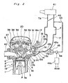
- the internal combustion engine E includes a cylinder block 3 (Fig. 2) having cylinder bores 3a formed therein, and a cylinder head 8 (Fig. 2) mounted on the upper portion of the cylinder block 3 to constitute cylinders 1 therebetween, with a piston P being movably accommodated in each of the cylinders bores 3a for reciprocating movements in the axial direction to define the combustion chamber 2 in said cylinder bore 3a.
- the first and second intake ports 4 and 5 of approximately the same diameter respectively provided with intake valves 15 are opened in a generally symmetrical relation with respect to a center line L in a widthwise direction of a cylinder block 3 (Fig. 2) of the engine E, while in a position confronting a second intake port 5, with a longitudinal center line M held therebetween, an exhaust port 6 provided with an exhaust valve 19 is opened for communication with an exhaust passage 40 to constitute an exhaust system.
- the intake system includes the main intake passage 7 which extends from an air cleaner 41, and includes. an upper passage portion 7A provided with a throttle valve 42 between the air cleaner 41 and a surge tank T, and lower passages 7B separated from the surge tank T so as to be led into the respective cylinders 1.
- the main intake passage 7 for supplying intake gases into the first and second intake ports 4 and 5 for each cylinder 1 is gradually divided within a cylinder head 8 (Fig. 2), and at a position immediately before the first and second intake ports 4 and 5, is bifurcated by a partition wall 9 formed to project or extend generally along the widthwise direction center line L, with branched intake passages 10 and 11 thus formed being respectively connected to the first and second intake ports 4 and 5.
- a center line L' of the intake passage 7 is slightly deviated towards the side of the first intake port 4 with respect to the widthwise direction center line L for a straight connection with the first intake port 4 as compared with the connection with respect to the second intake port 5, with the shutter valve 12 being provided at an upstream side thereof.
- an overlap portion between the main intake passage 7 and the branched intake passage 10 is larger, in area, than that between the main intake passage 7 and the branched intake passage 11.
- the shutter valve 12 is arranged, for example, to be associated with the throttle valve 42 so that it is closed during low load operation where the opening degree of the throttle valve 42 is comparatively small, and opened when the throttle valve 42 is opened beyond a predetermined opening degree.
- a .known open/close control mechanism for example, a link mechanism which is associated with the throttle valve 42 such that the shutter valve 12 is opened when the opening degree of the throttle valve 42 becomes large.
- a negative pressure actuator 45 for example, a three-way magnet valve 44, and a control unit 44c, etc.
- the negative pressure actuator 45 has a diaphragm 45a connected to an arm 12b fixed to a shaft 12a of the shutter valve 12 through a connecting rod 45b, and is communicated with the intake passage 7 at the downstream side of the throttle valve 42 through a pipe line 43 via the three-way magnet valve 44 to which data for the number N of revolutions of the engine (or engine speed) and throttle valve opening degree 0, are applied through the control unit 44c so as to be introduced into the actuator 45, a negative pressure in the close zone, and atmospheric air in the open zone.
- the shutter valve 12 is held in a closed state when intake air amount is small and is opened when the intake air amount is increased.
- the shutter valve 12 is intended to form a swirl S, such swirl may be produced even if the shutter valve 12 is not completely closed, and therefore, said shutter valve 12 is not necessarily fully closed even in the closed state, but it is possible that said valve 12 is slightly open even at the minimum degree of opening so as to allow air to flow towards the downstream side thereof.
- the above arrangement is preferable, since the fuel may be rapidly introduced into the cylinder in the case where a fuel injection port 18 to be described later is provided at the downstream side of the shutter valve 12. Namely, since opening and closing of the shutter valve 12 are controlled by signals of not only the engine load (e.g. the opening degree 8 of the throttle valve 42) but also the number N of revolutions of the engine E, it can be said that the shutter valve 12 is set in the closed state when the amount of the intake air is small and is opened when the amount of the intake air is increased.
- an upstream side opening 13a of the auxiliary intake passage 13 is opened in a bottom wall of the intake passage 7 so as to be deviated in position towards the side of the second intake port 5 with respect to the center line L' of the intake passage 7.
- the auxiliary intake passage 13 reterred to above has a downstream side opening 13b open in a position adjacent to the first intake port 4, and is gently curved so as to cross the center line L' of the intake passage 7 for communication of the upstream side opening 13a with the downstream side opening 13b.
- the above auxiliary intake passage 13 is formed in a bottom wall 14 constituting a bottom portion of the intake passage 7, and the downstream side opening 13b thereof is set in a position at a downstream side of the branching point for the bifurcated intake passages 10 and 11 and as close to the first intake port 4 to be opened or closed by the intake valve 15 as possible.
- the auxiliary intake passage 13 intersects with the bifurcated intake passage 10 which is curved at a large radius of curvature in an axial direction of the cylinder 1 at an immediately upstream side of the first intake port 4 in such a manner that said passage 13 forms a small angle of inclination with respect to a mating surface A between the cylinder block 3 and the cylinder head 8, thus being provided with a directivity in a circumferential direction of the combustion chamber 2. Accordingly, the intake gases drawn from the auxiliary intake passage 13 into the combustion chamber 2 produce vigorous swirling motions of the air-fuel mixture in the combustion chamber 2.
- the auxiliary intake passage 13 be oriented, in the vicinity of the downstream side opening 13b, substantially in a direction approximately tangential with respect to the inner face of the cylinder bore 3a.
- the auxiliary intake passage 13 is of a relatively small curve without being bent sharply as shown in Fig. 1, so that the auxiliary intake passage 13 is subjected to a small flow resistance.
- auxiliary intake passage 13 has a cross-sectional area smaller than that of each of the branched intake passages 10 and 11, the intake gases flow through the auxiliary intake passage 13 at a relatively high velocity even under the low load engine operating conditions in which the intake gases are small in amount.
- auxiliary intake passage 13 forms a small angle with the mating surface A between the cylinder block 3 and the cylinder head 8 and is oriented in the circumferential direction of the cylinder bore 3a as described above, the intake gases drawn from the auxiliary intake passage 13 into the combustion chamber 2 produce the vigorous swirling motions of the air-fuel mixture in the combustion chamber 2.
- the intake gases flowing through the main intake passage 7 substantially start flowing into the branched intake passages 10 and 11 such that the intake gases flowing through the auxiliary intake passage 13 are decreased in amount. Since the center line L' of the main intake passage 7 is deviated towards the first intake port 4 such that the overlap portion between the main intake passage 7 and the branched intake passage 10 is larger, in area, than that between the main intake passage 7 and the branched intake passage 11 as described above, the intake gases flowing from the main passage 7 through the branched intake passage 10 to the first intake port 4 are larger, in amount, than those flowing from the main intake passage 7 through the branched intake passage 11 to the second intake port 5.
- the intake gases proceeding from the branched intake passage 10 to the first intake port 4 flow together with the intake gases proceeding to the first intake port 4 through the auxiliary intake passage 10 so as to produce the swirling motions of the air-fuel mixture in the combustion chamber 2.
- the shutter valve 12 for selective opening or closing of the intake passage 7 is disposed so as to be inclined slantwise downwardly towards the downstream side, while at a fixing portion 16a provided on an upper wall 16 of the intake passage 7 slightly at a downstream side from the shutter valve 12, there is mounted a fuel injector 17.
- the fuel injection port 18 thereof is set in such a position at a slightly downstream side from the rotary shaft 12a of the shutter valve 12 and on the center line L' of the intake passage 7 (Fig. 1).
- the fuel jetted by the fuel injector 17 advances straight without spreading up to a certain distance, with a subsequent diffusion in a conical shape. Accordingly, when the fuel injection port 18 is set on the center line L' of the intake passage 7, owing to the fact that the center line L' is preliminarily deviated towards the side of the first intake port 4, a distribution ratio of the fuel diffused in the conical shape with respect to the first and second intake ports tends to be increased at the side of the first intake port 4.
- the shutter valve 12 is disposed between the upstream side opening 13a of the auxiliary intake passage 13 and the fuel injection port 18 in a posture inclined slantwise downwardly so as to be turned clockwise for opening from a fully closed position (a) shown by a solid line to a fully opened position (b) indicated by a dotted line in Fig. 2, it is possible to reduce a volume of the intake passage at the downstream side of the shutter valve 12 to the minimum during closing of the shutter valve 12.
- the fuel injector 17 is provided at the upstream side of the partition wall 9 for the first and second intake ports 4 and 5, and can not be disposed at an excessively downstream side, but if the shutter valve 12 required to be installed at the upstream side thereof is provided as described above, said valve 12 can be installed most close to the fuel injector 17, with a minimum space occupied thereby and therefore, the intake passage volume at the downstream side of the shutter valve 12 which becomes a dead volume or wasteful volume during closing of the shutter valve 12 may be reduced to the minimum.
- the shutter valve 12 since the shutter valve 12 is not necessarily fully closed even in the closed state thereof, with a possibility of opening to a certain extent even at the minimum opening degree for permitting air to flow towards the downstream side thereof as described earlier, the fuel may be rapidly introduced into the cylinder in the case where the fuel injection port 18 is provided at the downstream side of the shutter valve 12. More specifically, in the closed state (closed position) of the shutter valve 12, most of-the intake air is led into the cylinder 1 via the auxiliary intake passage 13 through the first intake port 4 so as to form a swirl perpendicular to the axial direction of the cylinder 1 and along the circumferential direction thereof.
- a small amount of air flows through a gap between the shutter valve 12 and the wall of the main intake passage 7, and is introduced into the cylinder 1 through both of the first and second intake ports 4 and 5.
- the swirl formed by the auxiliary intake passage 13 may be maintained to be properly strong.
- the intake valve 15 for opening or closing the first intake port 4 is respectively driven for opening and closing at predetermined timings synchronized with rotation of the engine E by a conventional overhead cam driving mechanism 20 provided on the upper portion of the cylinder head 8.
- the cam driving mechanism 20 includes a cam shaft 36 driven by a crank shaft (not shown) of the engine E, and a cam 37 formed on said cam shaft 36 and corresponding to the respective intake valves 15 and exhaust valve 19.
- the cam 37 engages one end of each rocking arm 38 provided to correspond to each of the intake valves 15 and exhaust valve 19, while the other end of the rocking arm 38 contacts each
- tappet 39 provided on a valve shaft of each of the valves 15 and 19 in a known manner.
- a spark plug 21 is disposed at a position where the first and second intake ports 4 and 5 and the exhaust port 6 are not provided, and more specifically, at a position where it confronts the first intake port 4 in which the auxiliary intake passage 13 is opened, with the longitudinal center line M of the combustion chamber 2 held therebetween.
- the shutter valve 12 When the throttle valve 42 is opened beyond a predetermined opening degree upon increase of the engine load, the shutter valve 12 is also caused to start opening. In an engine load range where the shutter valve 12 is opened slightly, a portion of the intake gases is still supplied into the combustion chamber 2 through the auxiliary intake passage 13. In this state, since the auxiliary intake passage 13 opens into only the intake port 4 and the upstream side opening 13a of the auxiliary intake passage 13 is disposed at the side of the second intake port 5, the intake gases supplied from the first intake port 4 into the combustion chamber 2 is larger, in amount, than those supplied from the second intake port 5 into the combustion chamber 2, whereby the air-fuel mixture can be swirled to some extent even under relatively increased load engine operating conditions.
- FIG. 5 there are shown in Fig. 5 variations of cross sectional shapes of the intake passage 7 with the cylinder head 8 taken along the lines (1) to (9) in Fig. 4 as indicated by the corresponding numbers in Fig. 5.
- the cross sectional shape of the intake passage 7 which is circular at first varies from an elliptic shape to a shape as in a figure eight towards the downstream side, and is then divided into the bifurcated intake passages 10 and 11 having two circular cross sections.
- the auxiliary intake passage 13 located below the main intake passage 7 and having a flat rectangular cross section, with a sufficiently small passage cross sectional area as compared with the passage cross section area of the intake passage 7, is gradually displaced from an initial position deviated towards the second intake port 5 in the main intake passage 7 (i.e., towards the right in Fig. 5) to a position at the side of the first intake port 4 (at the left side in Fig. 5) so as to cross the bottom wall of the bifurcated intake passage 10 connected to the first intake port 4 to finally open at the immediate upstream side of the first intake port 4.
- the auxiliary intake passage 13 formed in the bottom wall 14 constituting the bottom face of the main intake passage 7, is provided to make a comparatively small angle of inclination with respect to the mating surfaces A between the cylinder block 3 and the cylinder head 8, and as viewed from the top, is smoothly curved to cross the first intake port 4 from the side of the second intake port 5. Accordingly, particularly during the low load operation of the engine E in which the shutter valve 12 is totally closed, the intake gases tlowing down exclusively through the auxiliary intake passage 13 increase its velocity by being passed through the narrow passage and tlows into the combustion chamber 2 through the first intake port 4 while being directed towards the circumferential direction of the combustion chamber 2 thus generating a swirl in the circumferential direction within the combustion chamber 2.
- the swirl referred to above is formed in the circumterential direction of the combustion chamber 2, it is not readily attenuated or dampened, and is favorably ignited for combustion by the ignition of the spark plug 21 at the last stage of a compression stroke.
- the present invention is not limited, in its application, to such arrangement, but may be further modified in various ways within the scope.
- auxiliary intake passage 23 is formed straight along an extension line of the bifurcated intake passage 10 connected to the first intake port 4, with an upstream side opening 23a thereof being opened in the bottom wall of the intake passage 7 at the upstream side of the shutter valve 12, and a downstream side opening 23b thereof opened in the position adjacent to the first intake port 4.
- the intake arrangement of the present invention is applied to the engine provided with the fuel injector in the above embodiment but can be also applied to an engine provided with a carburettor.
- the air-fuel mixture can be vigorously swirled in the combustion chamber under the low load engine operating conditions, combustibility of the air-fuel mixture can be improved under the low load operating conditions, whereby the fuel consumption performance is improved and the exhaust emission is reduced.
- the auxiliary intake passage for feeding the intake gases into the combustion chamber under the low load engine operating conditions is connected to one of the intake ports, it becomes possible to supply the intake gases into the combustion chamber at a relatively high velocity in a direction deviated away from the center of the combustion chamber under the low load engine operating conditions where the intake gases are small in amount, so that the air-fuel mixture can be vigorously swirled in the combustion chamber.
- the air-fuel mixture can be swirled to some extent even in the engine load range where the shutter valve is caused to start opening, whereby it becomes possible to effect stable combustion of the air-fuel mixture in a relatively wide range of the low load engine operating conditions.
Landscapes
- Engineering & Computer Science (AREA)
- Chemical & Material Sciences (AREA)
- Combustion & Propulsion (AREA)
- Mechanical Engineering (AREA)
- General Engineering & Computer Science (AREA)
- Combustion Methods Of Internal-Combustion Engines (AREA)
- Cylinder Crankcases Of Internal Combustion Engines (AREA)
Applications Claiming Priority (6)
| Application Number | Priority Date | Filing Date | Title |
|---|---|---|---|
| JP58176777A JPS6075718A (ja) | 1983-09-24 | 1983-09-24 | エンジンの吸気装置 |
| JP176777/83 | 1983-09-24 | ||
| JP58202045A JPS6093119A (ja) | 1983-10-28 | 1983-10-28 | エンジンの吸気装置 |
| JP58202046A JPS6093120A (ja) | 1983-10-28 | 1983-10-28 | エンジンの吸気装置 |
| JP202045/83 | 1983-10-28 | ||
| JP202046/83 | 1983-10-28 |
Publications (3)
| Publication Number | Publication Date |
|---|---|
| EP0137393A2 true EP0137393A2 (fr) | 1985-04-17 |
| EP0137393A3 EP0137393A3 (en) | 1985-08-21 |
| EP0137393B1 EP0137393B1 (fr) | 1988-11-30 |
Family
ID=27324317
Family Applications (1)
| Application Number | Title | Priority Date | Filing Date |
|---|---|---|---|
| EP84111361A Expired EP0137393B1 (fr) | 1983-09-24 | 1984-09-24 | Agencement de canaux d'admission pour moteur à combustion interne |
Country Status (3)
| Country | Link |
|---|---|
| US (1) | US4625687A (fr) |
| EP (1) | EP0137393B1 (fr) |
| DE (1) | DE3475419D1 (fr) |
Cited By (6)
| Publication number | Priority date | Publication date | Assignee | Title |
|---|---|---|---|---|
| US4873953A (en) * | 1984-10-17 | 1989-10-17 | Nissan Motor Co., Ltd. | Induction port arrangement for internal combustion engine having multiple inlet valves per combustion chamber |
| DE3942637A1 (de) * | 1988-12-27 | 1990-06-28 | Fuji Heavy Ind Ltd | Verbrennungssystem |
| DE4439921A1 (de) * | 1993-11-08 | 1995-05-11 | Hitachi Ltd | Einlaßsystem einer Brennkraftmaschine |
| DE4439918A1 (de) * | 1993-11-08 | 1995-05-11 | Hitachi Ltd | Vorrichtung zur Zufuhr eines Kraftstoff/Luft-Gemisches zu einer Brennkraftmaschine |
| US5720255A (en) * | 1994-02-14 | 1998-02-24 | Yamaha Hatsudoki Kabushiki Kaisha | Control valve for multi-valve engine |
| DE4447938B4 (de) * | 1993-11-08 | 2005-03-10 | Hitachi Ltd | Einlaßsystem einer Brennkraftmaschine |
Families Citing this family (8)
| Publication number | Priority date | Publication date | Assignee | Title |
|---|---|---|---|---|
| JPH0415937Y2 (fr) * | 1985-10-14 | 1992-04-09 | ||
| KR880701323A (ko) * | 1986-05-21 | 1988-07-26 | 베네트 오토 모티브 테크놀로지 피티와이 리미티드 | 내연기관용 알코올 연료 작동 전환수단 |
| IT1223543B (it) * | 1987-12-18 | 1990-09-19 | Alfa Lancia Ind | Dispositivo di aspirazione per un motore a c.i. pluricilindrico |
| US4977866A (en) * | 1990-03-21 | 1990-12-18 | Don Wilkins | Flow control system for intake manifold |
| JP3003339B2 (ja) * | 1991-12-06 | 2000-01-24 | トヨタ自動車株式会社 | 燃料噴射式内燃機関の吸気装置 |
| JP3329935B2 (ja) * | 1994-04-28 | 2002-09-30 | 株式会社日立製作所 | 内燃機関の吸気装置 |
| DE10323978A1 (de) * | 2003-05-27 | 2004-12-16 | Adam Opel Ag | Brennkraftmaschine mit Kanalabschaltung und Zylinderkopf dafür |
| SE540850C2 (en) * | 2017-02-03 | 2018-11-27 | Scania Cv Ab | A compression ignited combustion engine |
Family Cites Families (12)
| Publication number | Priority date | Publication date | Assignee | Title |
|---|---|---|---|---|
| US3408992A (en) * | 1966-12-13 | 1968-11-05 | Ernest A. Von Seggern | Internal combustion engine and process utilizing heated auxiliary air to obtain complete combustion |
| JPS5489110A (en) * | 1977-12-26 | 1979-07-14 | Yamaha Motor Co Ltd | Method of controlling internal combustion engine |
| JPS54150516A (en) * | 1978-05-17 | 1979-11-26 | Yamaha Motor Co Ltd | Fuel feeder of fuel injection system engine |
| JPS6011205B2 (ja) * | 1978-08-10 | 1985-03-23 | ヤマハ発動機株式会社 | 内燃機関 |
| JPS608339B2 (ja) * | 1979-01-23 | 1985-03-02 | トヨタ自動車株式会社 | 燃料噴射式内燃機関の燃料噴射方法 |
| US4354463A (en) * | 1979-06-09 | 1982-10-19 | Honda Giken Kogyo Kabushiki Kaisha | Device for improving combustion efficiency of mixture in four cycle internal combustion engine |
| JPS5757022A (en) * | 1980-09-24 | 1982-04-06 | Nec Corp | Automatic equalizer |
| JPS5770914A (en) * | 1980-10-20 | 1982-05-01 | Yamaha Motor Co Ltd | Air intake controller for multi-valvetype internal combustionn engine |
| JPS5783631A (en) * | 1980-11-13 | 1982-05-25 | Suzuki Motor Co Ltd | Internal combustion engine |
| JPS6060011B2 (ja) * | 1981-02-19 | 1985-12-27 | トヨタ自動車株式会社 | 内燃機関の吸気装置 |
| JPS5857022A (ja) * | 1981-09-29 | 1983-04-05 | Yamaha Motor Co Ltd | エンジンの吸気装置 |
| JPS58135319A (ja) * | 1982-02-06 | 1983-08-11 | Suzuki Motor Co Ltd | 内燃機関の吸気装置 |
-
1984
- 1984-09-24 DE DE8484111361T patent/DE3475419D1/de not_active Expired
- 1984-09-24 EP EP84111361A patent/EP0137393B1/fr not_active Expired
-
1985
- 1985-12-27 US US06/815,287 patent/US4625687A/en not_active Expired - Fee Related
Cited By (14)
| Publication number | Priority date | Publication date | Assignee | Title |
|---|---|---|---|---|
| US4873953A (en) * | 1984-10-17 | 1989-10-17 | Nissan Motor Co., Ltd. | Induction port arrangement for internal combustion engine having multiple inlet valves per combustion chamber |
| DE3942637A1 (de) * | 1988-12-27 | 1990-06-28 | Fuji Heavy Ind Ltd | Verbrennungssystem |
| GB2226852A (en) * | 1988-12-27 | 1990-07-11 | Fuji Heavy Ind Ltd | I.c.engine charge intake and combustion chamber arrangement |
| GB2226852B (en) * | 1988-12-27 | 1993-06-30 | Fuji Heavy Ind Ltd | A combustion system of an internal combustion engine |
| US5564384A (en) * | 1993-11-08 | 1996-10-15 | Hitachi, Ltd. | Intake system for internal combustion engine |
| DE4439918A1 (de) * | 1993-11-08 | 1995-05-11 | Hitachi Ltd | Vorrichtung zur Zufuhr eines Kraftstoff/Luft-Gemisches zu einer Brennkraftmaschine |
| DE4439921A1 (de) * | 1993-11-08 | 1995-05-11 | Hitachi Ltd | Einlaßsystem einer Brennkraftmaschine |
| US5645029A (en) * | 1993-11-08 | 1997-07-08 | Hitachi, Ltd. | Intake system for internal combustion engine |
| US5765524A (en) * | 1993-11-08 | 1998-06-16 | Hitachi, Ltd. | Intake system for internal combustion engine |
| US5829408A (en) * | 1993-11-08 | 1998-11-03 | Hitachi, Ltd. | Internal combustion engine and air-fuel mixture supply apparatus therefor |
| DE4439918C2 (de) * | 1993-11-08 | 2002-06-20 | Hitachi Ltd | Vorrichtung zur Zufuhr eines Kraftstoff/Luft-Gemisches zu einer Brennkraftmaschine |
| DE4439921C2 (de) * | 1993-11-08 | 2002-10-24 | Hitachi Ltd | Einlaßsystem einer Brennkraftmaschine |
| DE4447938B4 (de) * | 1993-11-08 | 2005-03-10 | Hitachi Ltd | Einlaßsystem einer Brennkraftmaschine |
| US5720255A (en) * | 1994-02-14 | 1998-02-24 | Yamaha Hatsudoki Kabushiki Kaisha | Control valve for multi-valve engine |
Also Published As
| Publication number | Publication date |
|---|---|
| DE3475419D1 (en) | 1989-01-05 |
| EP0137393A3 (en) | 1985-08-21 |
| US4625687A (en) | 1986-12-02 |
| EP0137393B1 (fr) | 1988-11-30 |
Similar Documents
| Publication | Publication Date | Title |
|---|---|---|
| EP0137394B1 (fr) | Agencement de canaux d'admission pour moteur à combustion interne | |
| US4317438A (en) | High power output engine | |
| US4625687A (en) | Intake arrangement for internal combustion engine | |
| JPS59122725A (ja) | エンジンの吸気装置 | |
| JPS6060010B2 (ja) | 多気筒内燃機関の吸気装置 | |
| EP1081366B1 (fr) | Structure d'un canal d'admission pour un moteur à quatre temps | |
| JPS589249B2 (ja) | 多気筒内燃機関の吸気装置 | |
| US4519350A (en) | Intake system for an internal combustion engine | |
| US4770139A (en) | Engine combustion chamber structure | |
| JP2682694B2 (ja) | エンジンの吸気装置 | |
| JPH06159079A (ja) | エンジンの吸気装置 | |
| EP1111218A2 (fr) | Valve de commande du mouvement d'air dans le collecteur d'admission supérieur | |
| US4300500A (en) | Intake system of a multi-cylinder internal combustion engine | |
| US6543410B2 (en) | Direct injection engine | |
| US4553514A (en) | Internal combustion engine | |
| JP3591141B2 (ja) | 筒内直接噴射式火花点火内燃機関 | |
| EP0396557A1 (fr) | Moteurs a combustion interne. | |
| JPH0217689B2 (fr) | ||
| JPH0480210B2 (fr) | ||
| JPS6067719A (ja) | エンジンの吸気装置 | |
| JPS6093121A (ja) | エンジンの吸気装置 | |
| KR100203507B1 (ko) | 직분식 가솔린 엔진 | |
| JPH0236905Y2 (fr) | ||
| JPH0217690B2 (fr) | ||
| KR100222848B1 (ko) | 내연기관의 흡기 스월 발생구조 |
Legal Events
| Date | Code | Title | Description |
|---|---|---|---|
| PUAI | Public reference made under article 153(3) epc to a published international application that has entered the european phase |
Free format text: ORIGINAL CODE: 0009012 |
|
| 17P | Request for examination filed |
Effective date: 19840924 |
|
| AK | Designated contracting states |
Designated state(s): DE FR GB |
|
| PUAL | Search report despatched |
Free format text: ORIGINAL CODE: 0009013 |
|
| AK | Designated contracting states |
Designated state(s): DE FR GB |
|
| 17Q | First examination report despatched |
Effective date: 19861003 |
|
| GRAA | (expected) grant |
Free format text: ORIGINAL CODE: 0009210 |
|
| AK | Designated contracting states |
Kind code of ref document: B1 Designated state(s): DE FR GB |
|
| REF | Corresponds to: |
Ref document number: 3475419 Country of ref document: DE Date of ref document: 19890105 |
|
| ET | Fr: translation filed | ||
| PLBE | No opposition filed within time limit |
Free format text: ORIGINAL CODE: 0009261 |
|
| STAA | Information on the status of an ep patent application or granted ep patent |
Free format text: STATUS: NO OPPOSITION FILED WITHIN TIME LIMIT |
|
| 26N | No opposition filed | ||
| PGFP | Annual fee paid to national office [announced via postgrant information from national office to epo] |
Ref country code: FR Payment date: 19960910 Year of fee payment: 13 |
|
| PGFP | Annual fee paid to national office [announced via postgrant information from national office to epo] |
Ref country code: GB Payment date: 19960916 Year of fee payment: 13 |
|
| PGFP | Annual fee paid to national office [announced via postgrant information from national office to epo] |
Ref country code: DE Payment date: 19960927 Year of fee payment: 13 |
|
| PG25 | Lapsed in a contracting state [announced via postgrant information from national office to epo] |
Ref country code: GB Free format text: LAPSE BECAUSE OF NON-PAYMENT OF DUE FEES Effective date: 19970924 |
|
| PG25 | Lapsed in a contracting state [announced via postgrant information from national office to epo] |
Ref country code: FR Free format text: THE PATENT HAS BEEN ANNULLED BY A DECISION OF A NATIONAL AUTHORITY Effective date: 19970930 |
|
| GBPC | Gb: european patent ceased through non-payment of renewal fee |
Effective date: 19970924 |
|
| PG25 | Lapsed in a contracting state [announced via postgrant information from national office to epo] |
Ref country code: DE Free format text: LAPSE BECAUSE OF NON-PAYMENT OF DUE FEES Effective date: 19980603 |
|
| REG | Reference to a national code |
Ref country code: FR Ref legal event code: ST |