EP0139122A1 - Saugrohranlage für eine Brennkraftmaschine - Google Patents
Saugrohranlage für eine Brennkraftmaschine Download PDFInfo
- Publication number
- EP0139122A1 EP0139122A1 EP84109032A EP84109032A EP0139122A1 EP 0139122 A1 EP0139122 A1 EP 0139122A1 EP 84109032 A EP84109032 A EP 84109032A EP 84109032 A EP84109032 A EP 84109032A EP 0139122 A1 EP0139122 A1 EP 0139122A1
- Authority
- EP
- European Patent Office
- Prior art keywords
- intake
- cylinder head
- valve
- internal combustion
- connecting tube
- Prior art date
- Legal status (The legal status is an assumption and is not a legal conclusion. Google has not performed a legal analysis and makes no representation as to the accuracy of the status listed.)
- Granted
Links
Images
Classifications
-
- F—MECHANICAL ENGINEERING; LIGHTING; HEATING; WEAPONS; BLASTING
- F02—COMBUSTION ENGINES; HOT-GAS OR COMBUSTION-PRODUCT ENGINE PLANTS
- F02M—SUPPLYING COMBUSTION ENGINES IN GENERAL WITH COMBUSTIBLE MIXTURES OR CONSTITUENTS THEREOF
- F02M35/00—Combustion-air cleaners, air intakes, intake silencers, or induction systems specially adapted for, or arranged on, internal-combustion engines
- F02M35/10—Air intakes; Induction systems
- F02M35/10006—Air intakes; Induction systems characterised by the position of elements of the air intake system in direction of the air intake flow, i.e. between ambient air inlet and supply to the combustion chamber
- F02M35/10078—Connections of intake systems to the engine
- F02M35/10085—Connections of intake systems to the engine having a connecting piece, e.g. a flange, between the engine and the air intake being foreseen with a throttle valve, fuel injector, mixture ducts or the like
-
- F—MECHANICAL ENGINEERING; LIGHTING; HEATING; WEAPONS; BLASTING
- F02—COMBUSTION ENGINES; HOT-GAS OR COMBUSTION-PRODUCT ENGINE PLANTS
- F02M—SUPPLYING COMBUSTION ENGINES IN GENERAL WITH COMBUSTIBLE MIXTURES OR CONSTITUENTS THEREOF
- F02M35/00—Combustion-air cleaners, air intakes, intake silencers, or induction systems specially adapted for, or arranged on, internal-combustion engines
- F02M35/10—Air intakes; Induction systems
- F02M35/10091—Air intakes; Induction systems characterised by details of intake ducts: shapes; connections; arrangements
- F02M35/10144—Connections of intake ducts to each other or to another device
-
- F—MECHANICAL ENGINEERING; LIGHTING; HEATING; WEAPONS; BLASTING
- F02—COMBUSTION ENGINES; HOT-GAS OR COMBUSTION-PRODUCT ENGINE PLANTS
- F02M—SUPPLYING COMBUSTION ENGINES IN GENERAL WITH COMBUSTIBLE MIXTURES OR CONSTITUENTS THEREOF
- F02M35/00—Combustion-air cleaners, air intakes, intake silencers, or induction systems specially adapted for, or arranged on, internal-combustion engines
- F02M35/10—Air intakes; Induction systems
- F02M35/10209—Fluid connections to the air intake system; their arrangement of pipes, valves or the like
- F02M35/10216—Fuel injectors; Fuel pipes or rails; Fuel pumps or pressure regulators
-
- F—MECHANICAL ENGINEERING; LIGHTING; HEATING; WEAPONS; BLASTING
- F02—COMBUSTION ENGINES; HOT-GAS OR COMBUSTION-PRODUCT ENGINE PLANTS
- F02M—SUPPLYING COMBUSTION ENGINES IN GENERAL WITH COMBUSTIBLE MIXTURES OR CONSTITUENTS THEREOF
- F02M35/00—Combustion-air cleaners, air intakes, intake silencers, or induction systems specially adapted for, or arranged on, internal-combustion engines
- F02M35/10—Air intakes; Induction systems
- F02M35/10314—Materials for intake systems
- F02M35/10321—Plastics; Composites; Rubbers
-
- F—MECHANICAL ENGINEERING; LIGHTING; HEATING; WEAPONS; BLASTING
- F02—COMBUSTION ENGINES; HOT-GAS OR COMBUSTION-PRODUCT ENGINE PLANTS
- F02M—SUPPLYING COMBUSTION ENGINES IN GENERAL WITH COMBUSTIBLE MIXTURES OR CONSTITUENTS THEREOF
- F02M61/00—Fuel-injectors not provided for in groups F02M39/00 - F02M57/00 or F02M67/00
- F02M61/14—Arrangements of injectors with respect to engines; Mounting of injectors
- F02M61/145—Arrangements of injectors with respect to engines; Mounting of injectors the injection nozzle opening into the air intake conduit
-
- F—MECHANICAL ENGINEERING; LIGHTING; HEATING; WEAPONS; BLASTING
- F02—COMBUSTION ENGINES; HOT-GAS OR COMBUSTION-PRODUCT ENGINE PLANTS
- F02M—SUPPLYING COMBUSTION ENGINES IN GENERAL WITH COMBUSTIBLE MIXTURES OR CONSTITUENTS THEREOF
- F02M69/00—Low-pressure fuel-injection apparatus ; Apparatus with both continuous and intermittent injection; Apparatus injecting different types of fuel
- F02M69/04—Injectors peculiar thereto
- F02M69/042—Positioning of injectors with respect to engine, e.g. in the air intake conduit
- F02M69/044—Positioning of injectors with respect to engine, e.g. in the air intake conduit for injecting into the intake conduit downstream of an air throttle valve
-
- F—MECHANICAL ENGINEERING; LIGHTING; HEATING; WEAPONS; BLASTING
- F05—INDEXING SCHEMES RELATING TO ENGINES OR PUMPS IN VARIOUS SUBCLASSES OF CLASSES F01-F04
- F05C—INDEXING SCHEME RELATING TO MATERIALS, MATERIAL PROPERTIES OR MATERIAL CHARACTERISTICS FOR MACHINES, ENGINES OR PUMPS OTHER THAN NON-POSITIVE-DISPLACEMENT MACHINES OR ENGINES
- F05C2225/00—Synthetic polymers, e.g. plastics; Rubber
- F05C2225/08—Thermoplastics
Definitions
- the invention relates to an intake manifold system according to the preamble of claim 1.
- one of the engine components with the highest structure-borne noise levels is the cylinder head, which is mainly excited by excitations from combustion and gas exchange control.
- This structure-borne noise level means that considerable noise is emitted through the relatively large surfaces of the suction pipes.
- these noises are superimposed by high-frequency, pulse-like ticking noises at low engine speeds, some of which are emitted by the cylinder head, the intake manifolds and the fuel rail, but some are also radiated directly from the surface of the injection valves. Every time the residual engine noise is reduced, the ticker noises mentioned are subjectively disturbing.
- the object of the invention is to provide an intake manifold system of an internal combustion engine of the type mentioned at the outset with attached injection valves, in which additional noise-reducing effects on the internal combustion engine can be achieved. Furthermore, the attachment of the intake manifold on the cylinder head side should be permanent, secure and of high strength.
- an elastically designed tubular element preferably made of an elastomer or another elastic material, such as thermoplastic, is provided between the cylinder head and the intake lines, which at the same time has an encapsulating and structure-borne noise-isolating receptacle for an integrated injection valve.
- the proposed pipe element is used for effective structure-borne noise insulation of the intake manifolds of the cylinder head, whereby the noise emission is reduced.
- the pipe section is used to record the injection valves from structure-borne noise and encapsulation. This prevents high-frequency, pulse-like ticking noises, namely airborne sound insulation through the encapsulating enclosure, structure-borne noise insulation of the injection valves of the cylinder head and intake manifold, and structure-borne noise attenuation through the tightly enclosing elastomer sleeve.
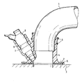
- An intake manifold system of an internal combustion engine comprises a plurality of intake lines 1, each of which is connected to a cylinder head 3 of the internal combustion engine via a flange 2. Between the cylinder head 3 and the individual intake lines 1, a structure-borne sound insulating connecting pipe 4 is provided. It consists of an elastic material, preferably an elastomer.
- a flange 2 made of the material of the connecting tube 4 is used, which is reinforced with a stiffening part 5 made of steel or an equivalent material.
- Bushings can also be provided in the flange, which are molded into the elastomer flange 2.
- connection of the elastic connecting pipe 4 to the metallic suction line 1 is made either by clamping rings 6, as shown, or the pipe is molded onto the suction line 1 by a known method.
- a sleeve-shaped receptacle 7 for an injection valve 8 is provided on the elastic connecting pipe 4.
- the receptacle 7 is made in one piece with the connecting tube 4.
- the receptacle 7 forms a capsule for the valve 8 and for this purpose is pulled up as far as possible according to the length of the valve.
- Corresponding molded beads 9 are provided within the receptacle for the form-fitting mounting of the valve 8.
- the receptacle 7 is designed in such a way that it tightly encloses the valve and covers the entire noise-radiating surface.
Landscapes
- Engineering & Computer Science (AREA)
- Chemical & Material Sciences (AREA)
- Combustion & Propulsion (AREA)
- Mechanical Engineering (AREA)
- General Engineering & Computer Science (AREA)
- Fuel-Injection Apparatus (AREA)
- Valve-Gear Or Valve Arrangements (AREA)
- Exhaust Gas After Treatment (AREA)
- Exhaust-Gas Circulating Devices (AREA)
Abstract
Description
- Die Erfindung bezieht sich auf eine Saugrohranlage nach dem Oberbegriff des Anspruchs 1.
- Bei einer Brennkraftmaschine ist eines der Motorenbauteile mit den höchsten Körperschallpegeln der Zylinderkopf, welcher hauptsächlich durch Anregungen aus der Verbrennung und der Gaswechselsteuerung erregt wird. Diese Körperschallpegel führen dazu, daß durch die relativ großen Oberflächen der Saugrohre erhebliche Geräusche abgestrahlt werden. Bei Motoren mit intermittierender Einspritzung überlagern sich diesen Geräuschen bei niedrigen Drehzahlen hochfrequente, impulsartige Tickergeräusche, die zu einem Teil vom Zylinderkopf, von den Saugrohren und vom Kraftstoffsammelrohr, zum anderen Teil aber auch direkt von der Oberfläche der Einspritzventile abgestrahlt werden. Bei jeder Reduzierung des Restmotorgeräusches treten die angesprochenen Tickergeräusche auch subjektiv störend hervor. Aus verschiedenen Konstruktionen ist es bekannt (DE-OS 28 24 205, DE-AS 11 56 276), die Ansaugleitungen unter Zwischenschaltung eines elastischen Flanschelementes mit dem Zylinderkopf zu verbinden, wodurch eine Schwingungsabkopplung vom Saugrohr zum Zylinderkopf und somit eine gewisse Körperschallisolation erzielt werden soll. Nachteilig wirkt sich hierbei aber das elastische Flanschelement auf die Haltbarkeit der Befestigung zum Zylinderkopf aus. Maßnahmen zur Minderung der Tickergeräusche der Einspritzventile sind aber nicht vorgesehen.
- Aufgabe der Erfindung ist es, eine Saugrohranlage einer Brennkraftmaschine der eingangs genannten Art mit angebauten Einspritzventilen zu schaffen, bei der sich ergänzende geräuschmindernde Wirkungen an der Brennkraftmaschine erzielen lassen. Desweiteren soll die zylinderkopfseitige Befestigung des Saugrohres dauerhaft, sicher und von hoher Festigkeit sein.
- Diese Aufgabe wird erfindungsgemäß durch die Merkmale des Anspruchs 1 gelöst. Weitere vorteilhafte Merkmale beinhalten die Unteransprüche.
- Die mit der Erfindung hauptsächlich erzielten Vorteile bestehen in einer Verminderung der Motorgeräuschemission. Hierzu ist zwischen dem Zylinderkopf und den Ansaugleitungen ein elastisch ausgebildetes Rohrelement, vorzugsweise aus einem Elastomer oder einem anderen elastischen Material, wie thermoplastischem Kunststoff, vorgesehen, das gleichzeitig eine kapselnde und körperschallisolierende Aufnahme für ein integriert angeordnetes Einspritzventil aufweist.
- Das vorgeschlagene Rohrelement dient zur wirkungsvollen Körperschallisolation der Saugrohre des Zylinderkopfes, wodurch die Geräuschabstrahlung vermindert wird. Zusätzlich dient das Rohrstück zur körperschallisolierenden und kapselnden Aufnahme der Einspritzventile. Damit werden hochfrequente, impulsartige Tickergeräusche unterbunden, und zwar erfolgt eine Luftschalldämmung durch die kapselnde Umschließung, eine Körperschallisolation der Einspritzventile von Zylinderkopf und Saugrohr und eine Körperschallbedämpfung durch die dicht umschließende Elastomerhülse.
- Ein Ausführungsbeispiel einer Luftansaugleitung mit einem elastischen Verbindungsrohr mit integriert angeordnetem Einspritzventil ist in der Zeichnung dargestellt und wird im folgenden näher beschrieben.
- Eine Saugrohranlage einer Brennkraftmaschine umfaßt mehrere Ansaugleitungen 1, die jeweils über einen Flansch 2 mit einem Zylinderkopf 3 der Brennkraftmaschine verbunden sind. Zwischen dem Zylinderkopf 3 und den einzelnen Ansaugleitungen 1 ist jeweils ein körperschallisolierendes Verbindungsrohr 4 vorgesehen. Es besteht aus einem elastischen Werkstoff, vorzugsweise aus einem Elastomer.
- Zur Verbindung mit dem Zylinderkopf 3 dient ein Flansch 2 aus dem Werkstoff des Verbindungsrohres 4, der mit einem Versteifungsteil 5 aus Stahl oder einem gleichwertigen Material verstärkt ist. Es können auch Buchsen im Flansch vorgesehen sein, die in den Elastomer-Flansch 2 eingeformt sind.
- Die Verbindung des elastischen Verbindungsrohres 4 mit der metallischen Ansaugleitung 1 erfolgt entweder durch Spannringe 6, wie dargestellt, oder das Rohr ist an die Ansaugleitung 1 durch ein bekanntes Verfahren angespritzt.
- Am elastischen Verbindungsrohr 4 ist eine hülsenförmige Aufnahme 7 für ein Einspritzventil 8 vorgesehen. Die Aufnahme 7 ist einstückig mit dem Verbindungsrohr 4 ausgeführt. Die Aufnahme 7 bildet eine Kapsel für das Ventil 8 und ist zu diesem Zweck entsprechend der Länge des Ventils weitmöglichst hochgezogen. Innerhalb der Aufnahme sind zur formschlüssigen Halterung des Ventils 8 entsprechende Formwülste 9 vorgesehen. Die Aufnahme 7 ist in der Weise ausgeführt, daß sie das Ventil dicht umschließt und die gesamte geräuschabstrahlende Oberfläche abdeckt.
Claims (6)
Applications Claiming Priority (2)
| Application Number | Priority Date | Filing Date | Title |
|---|---|---|---|
| DE19833333843 DE3333843A1 (de) | 1983-09-20 | 1983-09-20 | Saugrohranlage fuer eine brennkraftmaschine |
| DE3333843 | 1983-09-20 |
Publications (2)
| Publication Number | Publication Date |
|---|---|
| EP0139122A1 true EP0139122A1 (de) | 1985-05-02 |
| EP0139122B1 EP0139122B1 (de) | 1988-06-15 |
Family
ID=6209513
Family Applications (1)
| Application Number | Title | Priority Date | Filing Date |
|---|---|---|---|
| EP84109032A Expired EP0139122B1 (de) | 1983-09-20 | 1984-07-31 | Saugrohranlage für eine Brennkraftmaschine |
Country Status (4)
| Country | Link |
|---|---|
| US (1) | US4563984A (de) |
| EP (1) | EP0139122B1 (de) |
| JP (1) | JPS6088863A (de) |
| DE (2) | DE3333843A1 (de) |
Cited By (6)
| Publication number | Priority date | Publication date | Assignee | Title |
|---|---|---|---|---|
| EP0351520A3 (en) * | 1988-07-21 | 1990-06-06 | Dr.Ing.H.C. F. Porsche Aktiengesellschaft | Air inlet conduit for a combustion engine |
| EP0501612A3 (en) * | 1991-02-23 | 1992-10-21 | Jaguar Cars Limited | Inlet manifold and fuel supply assembly |
| FR2718812A1 (fr) * | 1994-04-18 | 1995-10-20 | Freudenberg Carl | Dispositif de fixation élastique pour la fixation d'un boîtier sur un moteur à combustion interne avec découplage des vibrations. |
| WO1997025529A1 (de) * | 1996-01-08 | 1997-07-17 | Robert Bosch Gmbh | Brennstoffeinspritzsystem |
| AT410245B (de) * | 1993-07-14 | 2003-03-25 | Bosch Gmbh Robert | Aus kunststoff bestehender formkörper |
| EP2148078A1 (de) * | 2008-07-24 | 2010-01-27 | Magneti Marelli Powertrain S.p.A. | Saugverteiler mit Zwischenflansch mit Dichtungen |
Families Citing this family (12)
| Publication number | Priority date | Publication date | Assignee | Title |
|---|---|---|---|---|
| JPS6288875U (de) * | 1985-11-22 | 1987-06-06 | ||
| GB2190138A (en) * | 1986-05-03 | 1987-11-11 | Ford Motor Co | A fuel rail for an i.c. engine |
| US5022371A (en) * | 1989-09-29 | 1991-06-11 | Siemens-Bendix Automotive Electronics L.P. | Molded plastic fuel rail for an internal combustion engine |
| US5003933A (en) * | 1989-11-06 | 1991-04-02 | General Motors Corporation | Integrated induction system |
| US5261375A (en) * | 1989-11-06 | 1993-11-16 | General Motors Corporation | Fuel injection assembly for integrated induction system |
| US5094194A (en) * | 1989-11-06 | 1992-03-10 | General Motors Corporation | Integrated induction system |
| US5232335A (en) * | 1991-10-30 | 1993-08-03 | General Electric Company | Interstage thermal shield retention system |
| FR2724419B1 (fr) * | 1994-09-09 | 1996-10-31 | Renault | Dispositif de fixation d'une tubulure d'admission de moteur a combustion interne |
| US5771863A (en) * | 1996-10-11 | 1998-06-30 | Siemens Electric Limited | Integrated intake manifold and fuel rail with enclosed fuel filter |
| US7007674B2 (en) | 2003-04-01 | 2006-03-07 | Robert Bosch Corporation | Fuel rail assembly |
| US6957643B2 (en) * | 2003-05-23 | 2005-10-25 | Siemens Vdo Automotive Inc. | Integrated carrier for vehicle intake manifold |
| US8985077B2 (en) | 2013-03-08 | 2015-03-24 | Ford Global Technologies, Llc | Valvetrain impact absorber |
Citations (2)
| Publication number | Priority date | Publication date | Assignee | Title |
|---|---|---|---|---|
| DE2824205A1 (de) * | 1978-06-02 | 1979-12-06 | Bayerische Motoren Werke Ag | Elastische flanschverbindungsanordnung |
| DE2835807A1 (de) * | 1978-08-16 | 1980-02-28 | Bosch Gmbh Robert | Kraftstoffversorgungs- und gemischbildungsanlage |
Family Cites Families (6)
| Publication number | Priority date | Publication date | Assignee | Title |
|---|---|---|---|---|
| DE1156276B (de) * | 1961-12-18 | 1963-10-24 | Volkswagenwerk Ag | Anordnung der Einlassleitung am Zylinderkopf von Brennkraftmaschinen |
| DE2242824C3 (de) * | 1972-08-31 | 1975-05-15 | Dr.-Ing.H.C. F. Porsche Ag, 7000 Stuttgart | Brennstoffeinspritzdüsenbefestigung |
| DE2501305A1 (de) * | 1975-01-15 | 1976-07-22 | Bayerische Motoren Werke Ag | Luftansauganlage fuer brennkraftmaschinen |
| SE430352B (sv) * | 1977-05-30 | 1983-11-07 | Honda Motor Co Ltd | Insugningsljuddempare for forbrenningsmotorer |
| JPS55107062A (en) * | 1979-02-13 | 1980-08-16 | Yamaha Motor Co Ltd | Fuel injection nozzle supporting construction of 4-cycle internal combustion engine |
| IT1152184B (it) * | 1982-05-17 | 1986-12-31 | Alfa Romeo Auto Spa | Guaina di protezione per un iniettore di benzina |
-
1983
- 1983-09-20 DE DE19833333843 patent/DE3333843A1/de not_active Withdrawn
-
1984
- 1984-07-31 DE DE8484109032T patent/DE3472139D1/de not_active Expired
- 1984-07-31 EP EP84109032A patent/EP0139122B1/de not_active Expired
- 1984-09-18 JP JP59194098A patent/JPS6088863A/ja active Pending
- 1984-09-20 US US06/652,513 patent/US4563984A/en not_active Expired - Fee Related
Patent Citations (2)
| Publication number | Priority date | Publication date | Assignee | Title |
|---|---|---|---|---|
| DE2824205A1 (de) * | 1978-06-02 | 1979-12-06 | Bayerische Motoren Werke Ag | Elastische flanschverbindungsanordnung |
| DE2835807A1 (de) * | 1978-08-16 | 1980-02-28 | Bosch Gmbh Robert | Kraftstoffversorgungs- und gemischbildungsanlage |
Non-Patent Citations (2)
| Title |
|---|
| PATENT ABSTRACTS OF JAPAN, Band 4, Nr. 158, 5 November 1980, (M-39) (640), Seite 23-M-39 & JP-A-55-107062 (YAMAHA) 16-08-1980 * Zusammenfassung * * |
| PATENT ABSTRACTS OF JAPAN, Band 7, Nr. 116, 20 Mai 1983, (M-216) (1261); & JP-A-58-35266 (MITSUBISHI) 01-03-1983 * |
Cited By (7)
| Publication number | Priority date | Publication date | Assignee | Title |
|---|---|---|---|---|
| EP0351520A3 (en) * | 1988-07-21 | 1990-06-06 | Dr.Ing.H.C. F. Porsche Aktiengesellschaft | Air inlet conduit for a combustion engine |
| EP0501612A3 (en) * | 1991-02-23 | 1992-10-21 | Jaguar Cars Limited | Inlet manifold and fuel supply assembly |
| AT410245B (de) * | 1993-07-14 | 2003-03-25 | Bosch Gmbh Robert | Aus kunststoff bestehender formkörper |
| FR2718812A1 (fr) * | 1994-04-18 | 1995-10-20 | Freudenberg Carl | Dispositif de fixation élastique pour la fixation d'un boîtier sur un moteur à combustion interne avec découplage des vibrations. |
| WO1997025529A1 (de) * | 1996-01-08 | 1997-07-17 | Robert Bosch Gmbh | Brennstoffeinspritzsystem |
| US5934252A (en) * | 1996-01-08 | 1999-08-10 | Robert Bosch Gmbh | Fuel injection system |
| EP2148078A1 (de) * | 2008-07-24 | 2010-01-27 | Magneti Marelli Powertrain S.p.A. | Saugverteiler mit Zwischenflansch mit Dichtungen |
Also Published As
| Publication number | Publication date |
|---|---|
| US4563984A (en) | 1986-01-14 |
| DE3333843A1 (de) | 1985-04-04 |
| DE3472139D1 (en) | 1988-07-21 |
| EP0139122B1 (de) | 1988-06-15 |
| JPS6088863A (ja) | 1985-05-18 |
Similar Documents
| Publication | Publication Date | Title |
|---|---|---|
| EP0139122B1 (de) | Saugrohranlage für eine Brennkraftmaschine | |
| DE19504223A1 (de) | Schalldämpfer für den Ansaugkanal einer Brennkraftmaschine | |
| DE102013211176A1 (de) | Kraftstoffhochdruckpumpe | |
| DE2948408A1 (de) | Elastisches lager, insbesondere fuer brennkraftmaschinen | |
| DE19643295C1 (de) | Brennstoffversorgungssystem | |
| DE102008045461A1 (de) | Akustische Seitenabdeckung für einen Motor | |
| DE10034726A1 (de) | Motorrad-Abgassystem | |
| EP0982491A2 (de) | Fördereinheit | |
| DE60024845T2 (de) | Unterdruckdichtung für einen luftansauganlageresonator | |
| DE10316570B4 (de) | Luftansaugsystem einer Brennkraftmaschine | |
| DE10030435B4 (de) | Geräuschdämpfer für ein Leerlauf-Bypassventil | |
| EP1520977B1 (de) | Ansaugvorrichtung für eine Vorreinigungseinrichtung in Verbindung mit einer Ventilatorverkleidung | |
| EP0358731B1 (de) | Axiallüfter | |
| DE102008017743A1 (de) | Schalldämpfer | |
| DE69619476T2 (de) | Befestigungsstruktur von Einspritzventilen für Brennkraftmaschinen | |
| EP1277947B1 (de) | Befestigungsvorrichtung für einen Ansaugverteiler | |
| DE202014104080U1 (de) | Motor-Schalldämpfung | |
| DE19920972A1 (de) | Befestigungsanordnung für ein Magnetventil | |
| DE102012206931A1 (de) | Anordnung mit einem Brennstoffverteiler und einem Halter | |
| DE2855220C2 (de) | ||
| DE2613607A1 (de) | Mehrzylindermotor-auspuffsystem mit zwei separaten auspuffleitungen | |
| DE19524431B4 (de) | Geräuschoptimierung einer Kraftstoffpumpe | |
| EP1342912A2 (de) | Kraftstoffversorgung für eine Brennkraftmaschine | |
| DE8218329U1 (de) | Ring fuer eine schwingungsdaempfende gelenkkupplung fuer auspuffschalldaempfer von kraftfahrzeugen | |
| DE9401610U1 (de) | Abgasanlage für Verbrennungsmotoren |
Legal Events
| Date | Code | Title | Description |
|---|---|---|---|
| PUAI | Public reference made under article 153(3) epc to a published international application that has entered the european phase |
Free format text: ORIGINAL CODE: 0009012 |
|
| AK | Designated contracting states |
Designated state(s): DE FR GB IT SE |
|
| RTI1 | Title (correction) | ||
| 17P | Request for examination filed |
Effective date: 19850829 |
|
| 17Q | First examination report despatched |
Effective date: 19860516 |
|
| GRAA | (expected) grant |
Free format text: ORIGINAL CODE: 0009210 |
|
| AK | Designated contracting states |
Kind code of ref document: B1 Designated state(s): DE FR GB IT SE |
|
| ITF | It: translation for a ep patent filed | ||
| GBT | Gb: translation of ep patent filed (gb section 77(6)(a)/1977) | ||
| REF | Corresponds to: |
Ref document number: 3472139 Country of ref document: DE Date of ref document: 19880721 |
|
| ET | Fr: translation filed | ||
| PLBE | No opposition filed within time limit |
Free format text: ORIGINAL CODE: 0009261 |
|
| STAA | Information on the status of an ep patent application or granted ep patent |
Free format text: STATUS: NO OPPOSITION FILED WITHIN TIME LIMIT |
|
| 26N | No opposition filed | ||
| PGFP | Annual fee paid to national office [announced via postgrant information from national office to epo] |
Ref country code: FR Payment date: 19910627 Year of fee payment: 8 |
|
| PGFP | Annual fee paid to national office [announced via postgrant information from national office to epo] |
Ref country code: SE Payment date: 19910701 Year of fee payment: 8 |
|
| PGFP | Annual fee paid to national office [announced via postgrant information from national office to epo] |
Ref country code: DE Payment date: 19910710 Year of fee payment: 8 |
|
| PGFP | Annual fee paid to national office [announced via postgrant information from national office to epo] |
Ref country code: GB Payment date: 19910719 Year of fee payment: 8 |
|
| ITTA | It: last paid annual fee | ||
| PG25 | Lapsed in a contracting state [announced via postgrant information from national office to epo] |
Ref country code: GB Effective date: 19920731 |
|
| PG25 | Lapsed in a contracting state [announced via postgrant information from national office to epo] |
Ref country code: SE Effective date: 19920801 |
|
| GBPC | Gb: european patent ceased through non-payment of renewal fee |
Effective date: 19920731 |
|
| PG25 | Lapsed in a contracting state [announced via postgrant information from national office to epo] |
Ref country code: FR Effective date: 19930331 |
|
| PG25 | Lapsed in a contracting state [announced via postgrant information from national office to epo] |
Ref country code: DE Effective date: 19930401 |
|
| REG | Reference to a national code |
Ref country code: FR Ref legal event code: ST |
|
| EUG | Se: european patent has lapsed |
Ref document number: 84109032.7 Effective date: 19930307 |