EP0140485A1 - Matériau d'écran pour câble et câble à écran électrique extensible - Google Patents
Matériau d'écran pour câble et câble à écran électrique extensible Download PDFInfo
- Publication number
- EP0140485A1 EP0140485A1 EP84305145A EP84305145A EP0140485A1 EP 0140485 A1 EP0140485 A1 EP 0140485A1 EP 84305145 A EP84305145 A EP 84305145A EP 84305145 A EP84305145 A EP 84305145A EP 0140485 A1 EP0140485 A1 EP 0140485A1
- Authority
- EP
- European Patent Office
- Prior art keywords
- sheet material
- transverse
- cable
- transverse folds
- metallic foil
- Prior art date
- Legal status (The legal status is an assumption and is not a legal conclusion. Google has not performed a legal analysis and makes no representation as to the accuracy of the status listed.)
- Granted
Links
- 239000000463 material Substances 0.000 title claims abstract description 87
- 239000011888 foil Substances 0.000 claims abstract description 61
- 239000004020 conductor Substances 0.000 claims abstract description 24
- 238000009413 insulation Methods 0.000 claims abstract description 9
- 239000000853 adhesive Substances 0.000 claims description 25
- 230000001070 adhesive effect Effects 0.000 claims description 25
- 238000000034 method Methods 0.000 claims description 11
- 230000008878 coupling Effects 0.000 claims 1
- 238000010168 coupling process Methods 0.000 claims 1
- 238000005859 coupling reaction Methods 0.000 claims 1
- XAGFODPZIPBFFR-UHFFFAOYSA-N aluminium Chemical compound [Al] XAGFODPZIPBFFR-UHFFFAOYSA-N 0.000 description 13
- 229910052782 aluminium Inorganic materials 0.000 description 13
- 238000010586 diagram Methods 0.000 description 9
- RYGMFSIKBFXOCR-UHFFFAOYSA-N Copper Chemical compound [Cu] RYGMFSIKBFXOCR-UHFFFAOYSA-N 0.000 description 8
- 229910052802 copper Inorganic materials 0.000 description 6
- 239000010949 copper Substances 0.000 description 6
- 239000011810 insulating material Substances 0.000 description 6
- 238000004519 manufacturing process Methods 0.000 description 6
- 238000010276 construction Methods 0.000 description 4
- 229920006267 polyester film Polymers 0.000 description 4
- 239000000758 substrate Substances 0.000 description 4
- 230000007423 decrease Effects 0.000 description 3
- 238000005065 mining Methods 0.000 description 3
- 239000004831 Hot glue Substances 0.000 description 2
- 239000011889 copper foil Substances 0.000 description 2
- 238000005336 cracking Methods 0.000 description 2
- QHZOMAXECYYXGP-UHFFFAOYSA-N ethene;prop-2-enoic acid Chemical compound C=C.OC(=O)C=C QHZOMAXECYYXGP-UHFFFAOYSA-N 0.000 description 2
- 229920006226 ethylene-acrylic acid Polymers 0.000 description 2
- 229920000728 polyester Polymers 0.000 description 2
- 239000000126 substance Substances 0.000 description 2
- 229920002725 thermoplastic elastomer Polymers 0.000 description 2
- 239000004698 Polyethylene Substances 0.000 description 1
- 239000004820 Pressure-sensitive adhesive Substances 0.000 description 1
- BQCADISMDOOEFD-UHFFFAOYSA-N Silver Chemical compound [Ag] BQCADISMDOOEFD-UHFFFAOYSA-N 0.000 description 1
- 230000005540 biological transmission Effects 0.000 description 1
- 235000019504 cigarettes Nutrition 0.000 description 1
- 230000002939 deleterious effect Effects 0.000 description 1
- 238000009826 distribution Methods 0.000 description 1
- 230000005489 elastic deformation Effects 0.000 description 1
- 210000003127 knee Anatomy 0.000 description 1
- 238000012986 modification Methods 0.000 description 1
- 230000004048 modification Effects 0.000 description 1
- 239000012811 non-conductive material Substances 0.000 description 1
- 238000007747 plating Methods 0.000 description 1
- -1 polyethylene Polymers 0.000 description 1
- 229920000573 polyethylene Polymers 0.000 description 1
- 229920001296 polysiloxane Polymers 0.000 description 1
- 230000002265 prevention Effects 0.000 description 1
- 230000002787 reinforcement Effects 0.000 description 1
- 238000009877 rendering Methods 0.000 description 1
- 238000007790 scraping Methods 0.000 description 1
- 230000035945 sensitivity Effects 0.000 description 1
- 229910052709 silver Inorganic materials 0.000 description 1
- 239000004332 silver Substances 0.000 description 1
- 239000007787 solid Substances 0.000 description 1
- 238000006467 substitution reaction Methods 0.000 description 1
Images



Classifications
-
- H—ELECTRICITY
- H01—ELECTRIC ELEMENTS
- H01B—CABLES; CONDUCTORS; INSULATORS; SELECTION OF MATERIALS FOR THEIR CONDUCTIVE, INSULATING OR DIELECTRIC PROPERTIES
- H01B11/00—Communication cables or conductors
- H01B11/02—Cables with twisted pairs or quads
- H01B11/06—Cables with twisted pairs or quads with means for reducing effects of electromagnetic or electrostatic disturbances, e.g. screens
- H01B11/10—Screens specially adapted for reducing interference from external sources
- H01B11/1016—Screens specially adapted for reducing interference from external sources composed of a longitudinal lapped tape-conductor
-
- H—ELECTRICITY
- H01—ELECTRIC ELEMENTS
- H01B—CABLES; CONDUCTORS; INSULATORS; SELECTION OF MATERIALS FOR THEIR CONDUCTIVE, INSULATING OR DIELECTRIC PROPERTIES
- H01B13/00—Apparatus or processes specially adapted for manufacturing conductors or cables
- H01B13/22—Sheathing; Armouring; Screening; Applying other protective layers
- H01B13/26—Sheathing; Armouring; Screening; Applying other protective layers by winding, braiding or longitudinal lapping
- H01B13/2613—Sheathing; Armouring; Screening; Applying other protective layers by winding, braiding or longitudinal lapping by longitudinal lapping
Definitions
- the present invention relates generally to electrical cable shields and more particularly to extensible electrical cable shields.
- EMI electromagnetic interference
- the shield of this cable comprises an expanded copper mesh, e.g., 4CU6-050 flattened annealed copper foil mesh produced by Delker Corporation, wrapped around the cable.
- This shield provides the advantages of extensibility and mechanical ruggedness. However, because the mesh is open and is inadequately conductive, its shielding characteristics are marginal or inadequate for many uses.
- Another means for shielding a ribbon cable or other cable is to cover the cable with a highly conductive metallic foil such as a copper or aluminum.
- a metallic foil such as a copper or aluminum.
- the foil is laminated to a polyester film for reinforcement.
- a continuous foil shield greatly reduces the flexibility of the cable.
- copper foil and aluminum foil tend to crack when repeatedly flexed.
- a continuous one mil thick aluminum foil shield bonded to a 50 mil (1.27 millimeters) thick cable core can be expected to show evidence of cracking after the second or third bend around a 3/8 inch (9.5 millimeters) diameter mandrel.
- braided wire shield The most widely used prior art shield for round cable has been braided wire.
- a braided wire shield When tightly woven and new, a braided wire shield provides high conductivity, high coverage, good to very good shielding and mechanical flexibility and ruggedness. Double layers of braid with silver plating are required for the best shielding performance.
- braided wire shields lose effectiveness with age because the connections between wires at cross-overs become unreliable. These conditions are even less certain when a braided shield is woven around a ribbon cable.
- the present invention provides a sheet material suitable for use as an electrical shield for an electrical cable particularly for a ribbon cable.
- the sheet material has a continuous metallic foil having a plurality of transverse folds.
- the transverse folds are flattened to form a plurality of transverse overlaps of the continuous metallic foil.
- the result is a sheet material in which the elongation of the sheet material exhibits a nonlinear yield behavior without cracking upon the application of a longitudinal force.
- the transverse folds of the sheet material form an interior angle of not more than three degrees.
- An adhesive may be applied to the sheet material either before or after forming the transverse folds. If desired, a removable liner can be attached to the adhesive rendering the sheet material easily handible prior to application to an electrical cable upon the removal of the liner.
- the present invention also provides an electrical cable having at least one conductor and insulation encasing the at least one conductor.
- the cable includes sheet material having a continuous metallic foil having a plurality of flattened transverse folds forming a plurality of transverse overlap of the continuous metallic foil. The transverse folds are transverse to the length of the cable. The sheet material is secured to the insulation.
- the present invention also involves a method of forming a sheet material suitable for use as a flexible electrical shield for an electrical cable.
- the method includes corrugating a sheet of continuous metallic foil to form a plurality of transverse folds and a second step of flattening the transverse folds of the continuous metallic foil.
- the method optionally further contains the step of applying adhesive to one side of the continuous metallic foil.
- the corrugating is accomplished in a regularly occurring manner forming regularly occurring transverse folds.
- the step of applying a liner to the adhesive can be utilized.
- the structure of the present invention provides a sheet material for, and a cable having, an extensible electrical shield which retains the desirable electrical characteristics of a continuous shield.
- the sheet material 10 illustrated in Figures 1 and 2 is formed from a continuous metallic foil 12 in which there is formed a plurality of transverse folds 14.
- the transverse folds 14 are flattened in the sheet material 12 to form an area of overlap 16 which yields surprising and unexpected advantageous performance of this sheet material for use as an extensible electrical shield for an electrical cable.
- the sheet material 10 may contain a liner 18 bonded to the flattened foil 12 with an adhesive 20.
- the adhesive 20 may either be applied before or after the flattening of the transverse folds of the metallic foil 12. In one embodiment, the adhesive 20 is applied before the sheet material 12 is flattened which results in the inclusion of a small amount of adhesive 20 within the overlap portion 16 of the transverse folds 14.
- the transverse folds 14 occur regularly over the longitudinal length of the sheet material 10.
- the amount of transverse overlap 16 of each of the plurality of transverse folds 14 is less than one third of the distance between successive ones of the transverse folds 14.
- the resulting sheet material 10 has a longitudinal extension of from 15 percent to 100 percent of its nonextended length.
- the amount of transverse overlap 16 of each of the plurality of transverse folds 14 is not more than 35 mils.
- the thickness of the continuous metallic foil 12 is between one half mil and two mils.
- the continuous metallic foil 12 may be constructed from a good metallic conductor such as copper or aluminum.
- the metallic foil 12 should be highly conductive, i.e., exhibit a sheet resistivity of not more than 20 x 10- 3 ohmo per square.
- the transverse folds 14 occur at approximately the rate of 15 transverse folds 14 per inch.
- the adhesive 20 is a hot melt adhesive such as an ethylene acrylic acid.
- the liner 18 is made from polyester.
- the sheet material 10 as illustrated in Figures 1 and 2 exhibits a nonlinear yield behavior on the application of longitudinal force. With the longitudinal force below a nominal yield value, the sheet material 10 acts as a continuous foil with a minimal amount of longitudinal extension and generally will return to near its original position upon the removal of that longitudinal force. With the application of a longitudinal force above the nominal yield amount, the sheet material 10 extends quite freely.
- the continuous metallic foil 12 may be purely a metallic foil as a copper or an aluminum foil, but it is preferred that the continuous metallic foil actually comprise a laminate of an aluminum foil with a polyester film.
- One embodiment utilizes Model 1001 film manufactured by the Facile Division of Sun Chemical Corporation which consists of a laminate of a 0.33 mil (0.008 millimeters) aluminum foil to a 0.5 mil (0.013 millimeters) polyester film.
- all references to a metallic foil 12 include-a metallic foil laminate with another conductive or nonconductive material such as polyester.
- a preferred embodiment utilizes Model 1112 adhesive coated one mil aluminum foil manufactured by the Facile Division of S un Chemical Corporation. This foil is coated with an ethylene acrylic acid hot melt adhesive which softens around 230° F (110°C).
- Figure 3 illustrates an electrical ribbon cable 22 constructed utilizing the sheet material 10.
- the insulating material 26 is sandwiched between sheet material 10 and bonded to the sheet material 10 with adhesive 20.
- the view in Figure 3 is looking through one of the transverse folds 14 of Figures 1 and 2.
- the conductors 24 and insulation 26 can be of conventional design such as Model 3365 ribbon cable manufactured by Minnesota Mining and Manufacturing Company, St. Paul, Minnesota.
- the conductors 24, are constructed from solid copper and in a preferred embodiment the insulating material 26 is constructed from polyethylene or low loss thermoplastic rubber (TPR).
- TPR polyethylene or low loss thermoplastic rubber
- FIG. 4 A longitudinal cross-section of the electrical ribbon cable 22 of Figure 3 is shown in Figure 4 which illustrates the transverse folds 14.
- a conductor 24 is encased in insulating material 26 and cigarette wrapped with sheet material 10 which is bonded to the insulating material 26 with adhesive 20.
- Adhesive 20 would not be required if, of course, the sheet material 10 already contained an adhesive as illustrated in Figure 1.
- Figure 5 illustrates the use of the sheet material 10 with an electrical cable 28 of circular cross section.
- the cable 28 consists of a plurality of conductors 30 some of which are surrounded by insulation 32.
- the conductors 30 are arranged in a generally circular cross section and are wrapped with the sheet material 10 again with the transverse folds 14 running transverse to the longitudinal direction of the cable 28.
- the sheet material 10 overlaps at overlap portion 34 to insure that the entire cable 28 is adequately shielded.
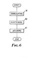
- FIG 6 illustrates a flow diagram describing the method of constructing the sheet material, and optionally an electrical cable utilizing the sheet material, of the present invention.
- the sheet material is formed by first corrugating 36 a sheet or strip of continuous metallic foil 12.
- the resulting corrugated metallic foil 38 is illustrated in Figure 7.
- the preferred method of corrugating 36 to the metallic foil 12 is to use two 0.415 inch (10.5 millimeters) outside diameter 48 diametral pitch meshing gears, then to run the continuous metallic foil through these meshing gears resulting in a corrugated metallic foil 38 having approximately 15 corrugations per inch (5.9 corrugations per centiemter).
- the corrugated metallic foil has an amplitude distance of approximately 35 mils (0.89 millimeters).
- the corrugated metallic foil 38 is then flattened 40 by sticking one side of the corrugations to a carrier (which may also be a liner) and then using a pair of nip rollers to flatten the corrugated metallic foil 38 to form a plurality of transverse folds 14 having transverse overlaps 16 as illustrated in Figure 8.
- the optional step of securing 41 the flattened sheet material 10 to an electrical cable may be accomplished with the use of a suitable adhesive.
- an adhesive be utilized with the corrugated metallic foil 38 in order to sufficiently adhere the corrugated material 38 to a substrate so that when flattened the corrugations of the corrugated metallic foil 38 would not "creep" while the flattening step 40 is being accomplished.
- the degree of restraint varys, of course, with the the nature of the corrugated metallic foil 38. It has been found, for example,, that with an aluminum foil under 1 mil (0.025 millimeters) in thickness that sufficient restraint could be obtained by scraping the corrugated metallic foil 38 flat while the corrugated metallic foil 38 was placed on 60 grit sandpaper. Heavier corrugated metallic foil require additional restraint, for example, a tacky adhesive surface.
- a usuable substrate, or ultimately a liner, which could be utilized for this restraint is a silicone pressure sensitive adhesive/polyester film tape identified as Model 8402POA manufactured by Minnesota Mining and Manufacturing Company, S t. Paul, Minnesota.
- This high temperature tape has a very low tack adhesive.
- the low tack of the adhesive to the substrate is advantageous in order to allow the flattened, corrugated metallic foil, the sheet material 10, to be stripped from the substrate without removing the flattened transverse folds forming a plurality of transverse overlaps.
- Figure 9 illustrates a stress-strain diagram illustrating the performance of the sheet material 10 of the present invention.
- the longitudinal force 42 or tensile force
- the tensile strain 44 or longitudinal extension
- the tensile strain 44 increases substantially linearly in the nonextension region 46 in which the sheet material 10 maintains substantially its original shape.
- the transverse folds 14 of the sheet material 10 begin to pull out.
- the folds continue to pull out during the pull out region 50 until all of the transverse folds 14 are extended at point 52.
- the tensile strain 44 of the sheet material 10 again continues to substantially linearly increase as the fully extended sheet material 10 resists the longitudinal force during the strain region 54.
- the longitudinal force 42 reaches the tensile strength of the materials forming the sheet material 10 at point 56, the sheet material 10 will tear resulting in the rapid decrease in tensile strain 44 during this tear region 58.
- FIG. 11 will more readily illustrate what is meant by the interior angle 64.
- sheet material 10 is shown with a transverse fold 14 tormed from faces 60 and 62 again the diagram of Figure 11 is distorted for ease of illustration.
- Face 62 of transverse fold 14 begins at point 68 at the base of interior angle 64 and continues to point 70 where the sheet material 10 folds back to continue to form the next transverse fold 14. If face 62 is not linear, either by design or subsequent deformation of the sheet material 10, the interior angle 64 is defined by a linear line drawn between points 68 and 70.
Landscapes
- Engineering & Computer Science (AREA)
- Manufacturing & Machinery (AREA)
- Physics & Mathematics (AREA)
- Electromagnetism (AREA)
- Shielding Devices Or Components To Electric Or Magnetic Fields (AREA)
- Insulated Conductors (AREA)
- Communication Cables (AREA)
Applications Claiming Priority (2)
| Application Number | Priority Date | Filing Date | Title |
|---|---|---|---|
| US518433 | 1983-07-29 | ||
| US06/518,433 US4533784A (en) | 1983-07-29 | 1983-07-29 | Sheet material for and a cable having an extensible electrical shield |
Publications (2)
| Publication Number | Publication Date |
|---|---|
| EP0140485A1 true EP0140485A1 (fr) | 1985-05-08 |
| EP0140485B1 EP0140485B1 (fr) | 1987-04-08 |
Family
ID=24063907
Family Applications (1)
| Application Number | Title | Priority Date | Filing Date |
|---|---|---|---|
| EP84305145A Expired EP0140485B1 (fr) | 1983-07-29 | 1984-07-27 | Matériau d'écran pour câble et câble à écran électrique extensible |
Country Status (6)
| Country | Link |
|---|---|
| US (1) | US4533784A (fr) |
| EP (1) | EP0140485B1 (fr) |
| JP (1) | JPS6044908A (fr) |
| CA (1) | CA1221145A (fr) |
| DE (1) | DE3463096D1 (fr) |
| ZA (1) | ZA845839B (fr) |
Families Citing this family (23)
| Publication number | Priority date | Publication date | Assignee | Title |
|---|---|---|---|---|
| US4647714A (en) * | 1984-12-28 | 1987-03-03 | Sohwa Laminate Printing Co., Ltd. | Composite sheet material for magnetic and electronic shielding and product obtained therefrom |
| WO1993006604A1 (fr) * | 1991-09-27 | 1993-04-01 | Minnesota Mining And Manufacturing Company | Structure amelioree de cable plat |
| US5360944A (en) * | 1992-12-08 | 1994-11-01 | Minnesota Mining And Manufacturing Company | High impedance, strippable electrical cable |
| CA2163702C (fr) * | 1995-11-24 | 2000-05-30 | Mark Beauchamp | Cable electrique resistant aux flammes |
| US5744756A (en) * | 1996-07-29 | 1998-04-28 | Minnesota Mining And Manufacturing Company | Blown microfiber insulated cable |
| US5900588A (en) * | 1997-07-25 | 1999-05-04 | Minnesota Mining And Manufacturing Company | Reduced skew shielded ribbon cable |
| US6166326A (en) * | 1998-12-01 | 2000-12-26 | Nakajima Tsushinki Kogyo Co., Ltd. | Metal cable |
| US6649828B2 (en) * | 2000-05-02 | 2003-11-18 | Custom Coated Components, Inc | Self-sealing reflective sleeve |
| US6744051B2 (en) * | 2001-11-16 | 2004-06-01 | Ge Medical Systems Global Technology Company Llc | High density electrical interconnect system for photon emission tomography scanner |
| JP2004111317A (ja) * | 2002-09-20 | 2004-04-08 | Mitsumi Electric Co Ltd | Emi抑止ケーブル |
| US20040130843A1 (en) * | 2002-12-24 | 2004-07-08 | Takaki Tsutsui | EMI suppressing cable and method of producing EMI suppressing cable |
| DE202004011400U1 (de) * | 2004-07-10 | 2005-11-24 | Coroplast Fritz Müller Gmbh & Co. Kg | Thermisch isolierendes technisches Klebeband sowie Kabelbaum hoher Temperaturbeständigkeit |
| EP1848612B1 (fr) * | 2005-02-14 | 2009-12-09 | Intier Automotive Inc. | Panneau de garniture avec faisceau de fils et procede servant a sa fabrication |
| US7536072B2 (en) * | 2005-03-29 | 2009-05-19 | Alcoa Inc. | Aluminum alloys for armored cables |
| US7522794B2 (en) * | 2005-03-29 | 2009-04-21 | Reynolds Packaging Llc | Multi-layered water blocking cable armor laminate containing water swelling fabrics and method of making such |
| USD632655S1 (en) * | 2007-07-13 | 2011-02-15 | Heyman Kenneth J | Cable cover |
| JP2012065448A (ja) * | 2010-09-16 | 2012-03-29 | Yazaki Corp | 導電路用シールド部材及びワイヤハーネス |
| KR101809531B1 (ko) * | 2011-06-09 | 2017-12-18 | 삼성전자주식회사 | 원통형 전자파 저지대 및 이를 포함하는 동축 케이블 |
| US9209510B2 (en) * | 2011-08-12 | 2015-12-08 | Commscope Technologies Llc | Corrugated stripline RF transmission cable |
| JP6424425B2 (ja) * | 2013-02-12 | 2018-11-21 | 株式会社デンソー | 回転電機 |
| KR102393119B1 (ko) * | 2016-09-30 | 2022-05-02 | 오브쉬체스트보 에스 오그라니첸노이 오트벳스트베노스트유 “오베디넨나야 꼼파니야 루살 인제네르노-테크놀로지체스키 첸트르” | 알루미늄 기반 합금으로 변형된 반제품 생산 방법 |
| WO2018090031A1 (fr) * | 2016-11-14 | 2018-05-17 | Amphenol Assembletech Co., Ltd | Câble plat haut débit ayant une meilleure mémoire en flexion/pliage et son procédé de fabrication |
| CN110767351B (zh) * | 2018-07-27 | 2021-04-20 | 浙江清华柔性电子技术研究院 | 可延展电子器件和制备方法 |
Citations (3)
| Publication number | Priority date | Publication date | Assignee | Title |
|---|---|---|---|---|
| DE749398C (de) * | 1936-12-24 | 1944-11-22 | Elektrische isolierte Leitung | |
| DE2735768A1 (de) * | 1976-08-10 | 1978-02-16 | Lignes Telegraph Telephon | Verfahren zum kontinuierlichen wellen von zwei metallbaendern |
| GB2120142A (en) * | 1982-05-10 | 1983-11-30 | Daifuku Machinery Works | Forming metal plates |
Family Cites Families (25)
| Publication number | Priority date | Publication date | Assignee | Title |
|---|---|---|---|---|
| US30194A (en) * | 1860-10-02 | billings | ||
| US2995616A (en) * | 1961-08-08 | Nicolas | ||
| DE345249C (fr) * | ||||
| CH168499A (de) * | 1932-12-01 | 1934-04-15 | Fankhauser Schraemli Lina | Faltkörper und Verfahren zu seiner Herstellung. |
| US2391037A (en) * | 1942-03-14 | 1945-12-18 | Bell Telephone Labor Inc | Armored conductor structure |
| US2391036A (en) * | 1942-03-14 | 1945-12-18 | Bell Telephone Labor Inc | Armored conductor structure |
| US2372323A (en) * | 1942-03-14 | 1945-03-27 | Bell Telephone Labor Inc | Armored conductor structure |
| FR1046954A (fr) * | 1951-12-15 | 1953-12-10 | Lignes Telegraph Telephon | Câble électrique à gaine métallique étanche et son procédé de fabrication |
| US2892007A (en) * | 1956-06-15 | 1959-06-23 | Gabriel Co | Coaxial line |
| GB918793A (en) * | 1960-07-04 | 1963-02-20 | Raymond Charles Mildner | Improvements in or relating to cables for transmitting high frequency currents |
| US3287490A (en) * | 1964-05-21 | 1966-11-22 | United Carr Inc | Grooved coaxial cable |
| US3339007A (en) * | 1965-07-28 | 1967-08-29 | Okonite Co | Power cables with an improved moisture barrier |
| US3509269A (en) * | 1968-06-11 | 1970-04-28 | Western Electric Co | Thermal barriers for cables |
| US3927247A (en) * | 1968-10-07 | 1975-12-16 | Belden Corp | Shielded coaxial cable |
| US3665096A (en) * | 1971-05-04 | 1972-05-23 | Us Air Force | Flexible cable shielding |
| USRE30194E (en) | 1973-10-01 | 1980-01-15 | Bunker Ramo Corporation | High frequency coaxial cable |
| US3968321A (en) * | 1973-10-03 | 1976-07-06 | General Cable Corporation | Offset "O" internal shield design for PCM telephone cables |
| US3963854A (en) * | 1974-12-05 | 1976-06-15 | United Kingdom Atomic Energy Authority | Shielded cables |
| JPS6018880B2 (ja) * | 1977-06-02 | 1985-05-13 | 日立電線株式会社 | 地下埋設低温タンクの冷熱防止方法 |
| US4260851A (en) * | 1979-07-02 | 1981-04-07 | Bell Telephone Laboratories, Incorporated | Built-in cable shield bonding system |
| JPS5631417U (fr) * | 1979-08-20 | 1981-03-27 | ||
| US4319473A (en) * | 1979-08-28 | 1982-03-16 | Western Electric Company, Inc. | Apparatus for corrugating a metal tape |
| US4297522A (en) * | 1979-09-07 | 1981-10-27 | Tme, Inc. | Cable shield |
| US4327246A (en) * | 1980-02-19 | 1982-04-27 | Belden Corporation | Electric cables with improved shielding members |
| US4376229A (en) * | 1980-09-16 | 1983-03-08 | Raychem Corporation | Shielded conduit |
-
1983
- 1983-07-29 US US06/518,433 patent/US4533784A/en not_active Expired - Lifetime
-
1984
- 1984-05-31 CA CA000455509A patent/CA1221145A/fr not_active Expired
- 1984-06-18 JP JP59124991A patent/JPS6044908A/ja active Granted
- 1984-07-27 ZA ZA845839A patent/ZA845839B/xx unknown
- 1984-07-27 DE DE8484305145T patent/DE3463096D1/de not_active Expired
- 1984-07-27 EP EP84305145A patent/EP0140485B1/fr not_active Expired
Patent Citations (3)
| Publication number | Priority date | Publication date | Assignee | Title |
|---|---|---|---|---|
| DE749398C (de) * | 1936-12-24 | 1944-11-22 | Elektrische isolierte Leitung | |
| DE2735768A1 (de) * | 1976-08-10 | 1978-02-16 | Lignes Telegraph Telephon | Verfahren zum kontinuierlichen wellen von zwei metallbaendern |
| GB2120142A (en) * | 1982-05-10 | 1983-11-30 | Daifuku Machinery Works | Forming metal plates |
Also Published As
| Publication number | Publication date |
|---|---|
| ZA845839B (en) | 1986-03-26 |
| JPS6044908A (ja) | 1985-03-11 |
| US4533784A (en) | 1985-08-06 |
| EP0140485B1 (fr) | 1987-04-08 |
| DE3463096D1 (en) | 1987-05-14 |
| CA1221145A (fr) | 1987-04-28 |
| JPH0372168B2 (fr) | 1991-11-15 |
Similar Documents
| Publication | Publication Date | Title |
|---|---|---|
| EP0140485B1 (fr) | Matériau d'écran pour câble et câble à écran électrique extensible | |
| US4475006A (en) | Shielded ribbon cable | |
| EP0608529B1 (fr) | Câble plat blindé | |
| US9129724B2 (en) | Shielded electrical cable | |
| US5900588A (en) | Reduced skew shielded ribbon cable | |
| EP0257855B1 (fr) | Câble ayant une cloison ondulée | |
| US3340353A (en) | Double-shielded electric cable | |
| EP0300334B1 (fr) | Utilisation d' un câble coaxial | |
| DE202017000284U1 (de) | Elektrisches Kabel | |
| GB1578158A (en) | Telecommunication cables | |
| JP2015138750A (ja) | 同軸ケーブル並びにこれを用いたフラットケーブル及びケーブルハーネス | |
| JP2002515630A (ja) | 電気信号ケーブル | |
| AU617626B2 (en) | Strippable shielded electric cable | |
| US20110253414A1 (en) | Metal-clad cable assembly | |
| JP2024126700A (ja) | フレキシブルフラットケーブル、及びフレキシブルフラットケーブルの製造方法 | |
| JPH0741051Y2 (ja) | シールド付フラットケーブル | |
| JP3403075B2 (ja) | フラットケーブルおよびその製造方法 | |
| JPH0433211A (ja) | シールド付テープ電線 | |
| JPH06309948A (ja) | ゴム、プラスチック絶縁電力ケーブル | |
| JP2979883B2 (ja) | シールド付フラットケーブル | |
| CN224217260U (zh) | 可调节内外径长度差的扁平式线缆 | |
| EP0429531B1 (fr) | Ecran electromagnetique comprenant une couche en elastomere contenant des particules de metal | |
| KR101207414B1 (ko) | 연성 플랫 케이블 | |
| JPH04147517A (ja) | シールド付きテープ電線 | |
| JPH0684632U (ja) | シールド積層電線 |
Legal Events
| Date | Code | Title | Description |
|---|---|---|---|
| PUAI | Public reference made under article 153(3) epc to a published international application that has entered the european phase |
Free format text: ORIGINAL CODE: 0009012 |
|
| AK | Designated contracting states |
Designated state(s): CH DE FR GB IT LI |
|
| 17P | Request for examination filed |
Effective date: 19851011 |
|
| 17Q | First examination report despatched |
Effective date: 19860702 |
|
| GRAA | (expected) grant |
Free format text: ORIGINAL CODE: 0009210 |
|
| ITF | It: translation for a ep patent filed | ||
| AK | Designated contracting states |
Kind code of ref document: B1 Designated state(s): CH DE FR GB IT LI |
|
| REF | Corresponds to: |
Ref document number: 3463096 Country of ref document: DE Date of ref document: 19870514 |
|
| ET | Fr: translation filed | ||
| PLBE | No opposition filed within time limit |
Free format text: ORIGINAL CODE: 0009261 |
|
| STAA | Information on the status of an ep patent application or granted ep patent |
Free format text: STATUS: NO OPPOSITION FILED WITHIN TIME LIMIT |
|
| 26N | No opposition filed | ||
| REG | Reference to a national code |
Ref country code: GB Ref legal event code: 732 |
|
| ITTA | It: last paid annual fee | ||
| PGFP | Annual fee paid to national office [announced via postgrant information from national office to epo] |
Ref country code: CH Payment date: 20000705 Year of fee payment: 17 |
|
| PG25 | Lapsed in a contracting state [announced via postgrant information from national office to epo] |
Ref country code: LI Free format text: LAPSE BECAUSE OF NON-PAYMENT OF DUE FEES Effective date: 20010731 Ref country code: CH Free format text: LAPSE BECAUSE OF NON-PAYMENT OF DUE FEES Effective date: 20010731 |
|
| REG | Reference to a national code |
Ref country code: GB Ref legal event code: IF02 |
|
| REG | Reference to a national code |
Ref country code: CH Ref legal event code: PL |
|
| PGFP | Annual fee paid to national office [announced via postgrant information from national office to epo] |
Ref country code: FR Payment date: 20030718 Year of fee payment: 20 |
|
| PGFP | Annual fee paid to national office [announced via postgrant information from national office to epo] |
Ref country code: GB Payment date: 20030723 Year of fee payment: 20 |
|
| PGFP | Annual fee paid to national office [announced via postgrant information from national office to epo] |
Ref country code: DE Payment date: 20030731 Year of fee payment: 20 |
|
| PG25 | Lapsed in a contracting state [announced via postgrant information from national office to epo] |
Ref country code: GB Free format text: LAPSE BECAUSE OF EXPIRATION OF PROTECTION Effective date: 20040726 |
|
| REG | Reference to a national code |
Ref country code: GB Ref legal event code: PE20 |