EP0141948A1 - Verfahren und Vorrichtung zum durchlaufenden Rektifizieren von Eisenbahnschienen - Google Patents
Verfahren und Vorrichtung zum durchlaufenden Rektifizieren von Eisenbahnschienen Download PDFInfo
- Publication number
- EP0141948A1 EP0141948A1 EP84110413A EP84110413A EP0141948A1 EP 0141948 A1 EP0141948 A1 EP 0141948A1 EP 84110413 A EP84110413 A EP 84110413A EP 84110413 A EP84110413 A EP 84110413A EP 0141948 A1 EP0141948 A1 EP 0141948A1
- Authority
- EP
- European Patent Office
- Prior art keywords
- rail
- polygon
- profile
- grinding
- function
- Prior art date
- Legal status (The legal status is an assumption and is not a legal conclusion. Google has not performed a legal analysis and makes no representation as to the accuracy of the status listed.)
- Granted
Links
Images


Classifications
-
- E—FIXED CONSTRUCTIONS
- E01—CONSTRUCTION OF ROADS, RAILWAYS, OR BRIDGES
- E01B—PERMANENT WAY; PERMANENT-WAY TOOLS; MACHINES FOR MAKING RAILWAYS OF ALL KINDS
- E01B31/00—Working rails, sleepers, baseplates, or the like, in or on the line; Machines, tools, or auxiliary devices specially designed therefor
- E01B31/02—Working rail or other metal track components on the spot
- E01B31/12—Removing metal from rails, rail joints, or baseplates, e.g. for deburring welds, reconditioning worn rails
- E01B31/17—Removing metal from rails, rail joints, or baseplates, e.g. for deburring welds, reconditioning worn rails by grinding
Definitions
- the transverse profiles of the rails for railway tracks have been determined by calculation and experimentally, they have been improved over the years to optimize the requirements of the easiest manufacturing possible on the one hand and on the other hand the requirements relating to the safety and comfort of running convoys.
- the UIC has defined several transverse profiles for the rails, one of the most frequently used of which is the UIC 60, illustrated in FIG.
- an angle yn is defined as being the angle between a straight line D tangent to the profile of the rail head perpendicular to the vertical axis of symmetry x of the rail and the tangent Tn to the profile of the rail head at point N;
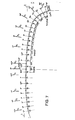
- the transverse profile of the rail can be represented graphically by plotting for each point of the profile on the ordinate the radius of curvature of the rail and on the abscissa the angle y.
- this graphic representation is given in Figure 2.
- the tire profiles of the wheels of the railway vehicles were likewise determined by calculation and experience.
- the rail and bandage profiles are conjugate profiles.
- wave wear gradually forms as well as a significant deterioration of the average wear profile, more or less significant burrs can form.
- the rails are reprofiled, in particular by grinding; operation which aims to give the rail a correct transverse profile.
- a reprofiling process by grinding is described in patent CH 592,780 according to which one continuously moves along the rails several grinding units, forming angles between them and therefore grinding different generators of the rail whose pressure is adjusted, and therefore the cutting depth, depending on the differences existing for each generator concerned between the original profile and the actual profile of the rail.
- the present invention relates to a method and a device for rectifying the rails of a continuous rail track, in particular for the finishing passes of reprofiling rails such as as defined in the independent claims of this patent.
- the present method relates to the reshaping of the rails of a railway track using grinding tools mounted on carriages rolling on the rails and connected to a rail vehicle by members ensuring their traction along the rails and their application against these rails.
- the licensee set itself the goal of eliminating the arbitrary uncertainties and adjustments relating to the positioning of the grinding wheels as well as their bearing pressure by defining a rigorous method for the determination of these parameters.
- the first operation of the present method consists in defining for a section of the rail network to be rectified a satisfactory average wear profile o It is this average profile which will serve as a reference profile for the finishing of the rail reprofiling.
- This mean wear or reference profile is represented for example in FIG. 3 and it is characterized by the fact that for each of these points N, N + 1 it has another radius of curvature Rn, Rn + 1.
- the average reference wear profile for reshaping the second step of the present method consists in defining a polygon circumscribed by this reference profile.
- This polygon or rather at least one of its parameters, such as number of facets n, the angle at the center a between the facets, the angle between two facets Ay, the width of the facets L, is determined as a function of the quality of finish of the desired reprofiling.
- the polygon circumscribed to the reference profile is unambiguously defined on the one hand by said profile and on the other hand by a parameter of the polygon determined itself as a function of the precision of the desired reprofiling, in particular the number of sides , the angle between sides, etc.
- the third operation of the present method consists in positioning the grinding units so that the active surface of each grinding wheel is parallel or tangent to one side of the previously determined polygon.
- the fourth operation of the present method consists in adjusting the pressure of support of each grinding unit against the rail as a function of at least one parameter. on the side of the polygon with which it is associated.
- the inclination of the axes of the grinding units relative to the plane of symmetry of the rail is, as so far, determined only by the judgment of the grinding personnel.
- This adjustment of the angular position of the grinding units being carried out, each grinding wheel is located on one side of a polygon circumscribed to the rail.
- the pressing pressure of each grinding wheel against the rail is determined as a function of one or more parameters of this polygon, and no longer arbitrarily as so far.
- FIG. 5 very schematically illustrates the original basic principle of the method according to the present invention.
- This figure shows a part of the mean wear profile 5 for reference of a section of track to be reprofiled.
- the broken line 6 materializes the polygon circumscribed to the reference profile 5 comprising in the example illustrated four facets for each side of the rail covering the running table, the intermediate zone and the fillet.
- the number of facets or sides of this polygon is determined according to the precision of the desired finishing reprofiling. In reality, this polygon could have more than eight facets covering the entire profile of the rail head. The greater the number of facets, the greater the precision of the reshaping, but the greater the number of grinding tools, respectively of work passes.
- This polygon circumscribed to the reference profile can be determined by parameters other than its number of sides. For example we can impose that the angle between ⁇ facets either constant, or varies depending on the radius of curvature of the reference profile. It can also be imposed that the length of the sides L of this polygon is constant or a function of the radius of curvature of the reference profile.
- Line 7 shows a real profile of the rail head to be reprofiled.
- Each facet corresponds to a facet width L1, L2, L3, L4; an angle yl, y2, y3, y4 that the facet forms with a straight line tangent to the reference profile 5 and perpendicular to the x axis; an angle ⁇ 1 , ⁇ 2 , ⁇ 3 , ⁇ 4 formed by the envisaged side with the adjacent side situated on the side of the axis x of the rail, a mean radius of curvature R 1 , R 2 , R 3 , R4; an angle at the center ⁇ 1 , a 21 ⁇ 3 , ⁇ 4 ; a cutting depth C 1 , C 2 ′ C 3 , C 4 represented by the distance separating, at the midpoint of the side envisaged, the real profile 7 from the side of the polygon 6; and finally a removal surface S
- the choice of the circumscribed polygon depends on the quality or finish of the desired reprofiling, it is possible for example in the first finishing passes to define a polygon whose metal removal surfaces S would be constant and equal to a maximum value. Thus, at the start of the finish, the maximum amount of metal would be removed per pass.
- the circumscribed polygon which finally corresponds to the profile of the reprofiled rail, fits as best as possible to the reference profile 5 and it is a polygon where the angle between facets ⁇ will be chosen constant or function of the radius of curvature R which will be preferred.
- the polygon determined according to the required quality of the reprofiling, can be limited to the original profile or to the actual profile of the rail and not to its average profile. of wear.
- the essence of the present reprofiling process of a rail consists in moving along a line of rails of a railway track, a set of rail grinding units, angularly offset by one relative to the others and to regulate the pressure with which each of these grinding units is applied against the rail as a function of at least one parameter of a polygon circumscribed to a reference profile and whose sides are parallel to the active surfaces of the grinding wheels grinding units.
- each grinding unit against the rail is thus a function of the position of the corresponding facet relative to the axis of symmetry of the rail, that is to say a function of the angular offset y of l 'grinding unit with respect to this axis of symmetry of the rail, generally approximately vertical; on the other hand this pressure is also a function of the width L of the envisaged side or of the desired depth of cut C for example or of a combination of these parameters. It can also be a function of metal surface to be removed S.
- the method also provides that the polygon or some of its parameters are defined as a function of the quality of the reprofiling desired, the polygon in question is defined as being a polygon circumscribed in the profile that one wishes to reconstruct either the original profile or better still the average wear profile of the rail, although in the case of the simplified method this polygon may be circumscribed to the actual profile of the worn rail.
- the device for implementing the method described comprises a set of grinding units 10 carried by a carriage 11 guided by the rail 12, each comprising a motor 13 for driving a lapidary wheel 14 in rotation.
- a jack 15 makes it possible to apply the grinding wheel 14 against the rail with a determined force.
- Each unit 10 is angularly movable relative to the carriage 11 and therefore relative to the other grinding units carried by this carriage 11.
- Each grinding unit further comprises a motor 16 controlling the inclination of this unit relative to the carriage and a sensor 17 measuring the angle of inclination of this unit 10 relative to the carriage 11.
- Each grinding unit is controlled by a control circuit 18 comprising on the one hand a servo-control of the inclination of the unit and on the other hand a servo-control of the bearing force of the grinding wheel 14 against the rail 12.
- the tilt control of the grinding unit 10 comprises an angle selector 19 supplied by a memory 22 containing the parameters of the polygon, in particular the angular position of its facets, and selects for each grinding unit the facet of the polygon to which the active face of the grinding wheel must be parallel and therefore the degree of inclination of the grinding unit 11 relative to the carriage 12.
- the signal delivered by this selector 19 supplies the first input of an angle error detector 20 whose other input is supplied by the output of the sensor 17. As soon as a difference is detected between the inputs of the error detector 20, the latter delivers a signal to the amplifier 21 which controls the motor 16.
- the control of the pressing pressure of the grinding wheel 14 against the rail 12 comprises a calculator 23 powered by the memory 22 and the tilt selector 19. This calculator determines as a function of at least one parameter of the polygon stored at 22 and where appropriate, taking into account the angle of inclination of the unit, a control value which is delivered to a servo-valve 24 controlling the supply of the jack 15 by a source of fluid 25.
- a calculator 26 containing in memory the information relating to the reference profile determined by the quality of the desired reprofiling, determines the parameters of the polygon as a function of said profile and of information I defining the desired quality of finish. These parameters or characteristics of the polygon are stored at 22.
- FIG. 7 illustrates a polygon circumscribed with the desired reference profile comprising 24 grinding facets or sides of the polygon distributed over the rolling surface of the rail, the internal fillet of the latter and the rolling zone between these two parts.
- This polygon circumscribed to the reference profile is determined according to the quality of the desired reprofiling, in this precise case the width of the grinding facets, that is to say the length of the sides of the polygon, is a function of the radius of curvature of the reference profile.
- the side of the polygon centered on the vertical axis of the rail is of 3.46 mm as well as the following facet.
- the third facet from the axis of the rail has a width of 3.16 mm the 4, 5, 6, 7 and 8 facets a width of 2.79 mm, the ninth a width of 2.52 mm and the rest a width of 2.27 mm.
- a machine comprising four carriages A, B, C, D each carrying two grinding units.
- the grinding units of a carriage A are angularly offset from each other by 10 ° while the grinding units of the other three carriages B, C, D are offset from each other by 2 °
- the finishing reprofiling is carried out in three successive passes during which the four carriages occupy different angular positions relative to the rail.
- the carriage A In a first pass, relative to the longitudinal plane of the rail, the carriage A is offset at 28 °, the carriage B at 4 °, the carriage C at - 0.7 ° and the carriage D at - 12 °. During this machining pass the sides 6, 5; 11.12; 18, 15 and 23, 24 are reprofiled. In a second machining pass, the carriage A is offset at 48 °, the carriage B at 8 °, the carriage C at 0 ° and the carriage D at - 8 ° The sides 3.4; 9.10; 14.17; and 21.22 are reprofiled.
- the carriage A is offset at 68 °, the carriage B at 12 °, the carriage C at 0.7 ° and the carriage D at - 4 ° and the sides 1.2; 7.8; 13.15; and 19.20 are reprofiled.
- the grinding pressure is the pressure of each wheel against the rail is in this particular case function of the angle y on the side of the polygon and of its width L.
- a polygon circumscribed on the reference profile is determined, the width of the sides of which is a function of the radius of curvature of the reference profile; then the grinding wheels are placed parallel to the sides of this polygon, the pressure of each grinding wheel against the rail being determined as a function of the angle of the corresponding side of the polygon and of its width so that the surface of metal to be removed S corresponding to each side of the polygon is effectively ground.
- each grinding unit comprises two motors each driving a grinding wheel.
- Each unit therefore comprises a pair of grinding wheels applied against the rail with the same force coming from application means common to the grinding unit.
Landscapes
- Engineering & Computer Science (AREA)
- Mechanical Engineering (AREA)
- Architecture (AREA)
- Civil Engineering (AREA)
- Structural Engineering (AREA)
- Machines For Laying And Maintaining Railways (AREA)
- Grinding And Polishing Of Tertiary Curved Surfaces And Surfaces With Complex Shapes (AREA)
- Paper (AREA)
- Investigating Or Analyzing Materials By The Use Of Ultrasonic Waves (AREA)
- Train Traffic Observation, Control, And Security (AREA)
- Control Of Vehicles With Linear Motors And Vehicles That Are Magnetically Levitated (AREA)
- Current-Collector Devices For Electrically Propelled Vehicles (AREA)
Priority Applications (1)
| Application Number | Priority Date | Filing Date | Title |
|---|---|---|---|
| AT84110413T ATE25271T1 (de) | 1983-09-16 | 1984-09-01 | Verfahren und vorrichtung zum durchlaufenden rektifizieren von eisenbahnschienen. |
Applications Claiming Priority (2)
| Application Number | Priority Date | Filing Date | Title |
|---|---|---|---|
| CH5052/83 | 1983-09-16 | ||
| CH5052/83A CH654047A5 (fr) | 1983-09-16 | 1983-09-16 | Procede et dispositif pour le reprofilage en continu des rails d'une voie ferree. |
Publications (2)
| Publication Number | Publication Date |
|---|---|
| EP0141948A1 true EP0141948A1 (de) | 1985-05-22 |
| EP0141948B1 EP0141948B1 (de) | 1987-01-28 |
Family
ID=4287148
Family Applications (1)
| Application Number | Title | Priority Date | Filing Date |
|---|---|---|---|
| EP84110413A Expired EP0141948B1 (de) | 1983-09-16 | 1984-09-01 | Verfahren und Vorrichtung zum durchlaufenden Rektifizieren von Eisenbahnschienen |
Country Status (9)
| Country | Link |
|---|---|
| US (1) | US4905422A (de) |
| EP (1) | EP0141948B1 (de) |
| JP (1) | JPS6095003A (de) |
| AT (1) | ATE25271T1 (de) |
| AU (1) | AU566436B2 (de) |
| CA (1) | CA1253344A (de) |
| CH (1) | CH654047A5 (de) |
| DE (2) | DE3462278D1 (de) |
| ZA (1) | ZA847125B (de) |
Cited By (3)
| Publication number | Priority date | Publication date | Assignee | Title |
|---|---|---|---|---|
| GB2189051A (en) * | 1984-03-29 | 1987-10-14 | Rail Profiling Holdings Inc | Automated railway track maintenance system |
| EP0235602A3 (en) * | 1986-02-28 | 1988-10-12 | Les Fils D'auguste Scheuchzer S.A. | Process for measuring and grinding a rail head profile |
| FR2750632A1 (fr) * | 1996-07-08 | 1998-01-09 | Efsa | Procede et dispositif de meulage d'une surepaisseur d'une piece metallique |
Families Citing this family (20)
| Publication number | Priority date | Publication date | Assignee | Title |
|---|---|---|---|---|
| US4779384A (en) * | 1986-02-13 | 1988-10-25 | Harsco Corporation | Rail grinder |
| JPS62233308A (ja) * | 1986-03-31 | 1987-10-13 | 芝浦メカトロニクス株式会社 | レ−ル頭部削正装置 |
| CH680672A5 (de) * | 1989-08-28 | 1992-10-15 | Speno International | |
| CH680597A5 (de) * | 1989-08-28 | 1992-09-30 | Speno International | |
| CH680598A5 (de) * | 1989-08-28 | 1992-09-30 | Speno International | |
| GB2241063B (en) * | 1990-02-14 | 1994-01-05 | Rolls Royce Plc | Monitoring a machining operation |
| CH685129A5 (fr) * | 1991-03-01 | 1995-03-31 | Speno International | Dispositif pour le reprofilage des rails d'une voie ferrée. |
| US5271204A (en) * | 1992-01-21 | 1993-12-21 | Wolf Morris A | Lightweight display post and method of making same |
| CH689643A5 (fr) * | 1994-02-18 | 1999-07-30 | Speno International | Installation pour le reprofilage des rails d'une voie ferrée. |
| CH689642A5 (fr) * | 1994-02-18 | 1999-07-30 | Speno International | Installation pour le reprofilage des rails d'une voie ferrée. |
| CH690963A5 (fr) * | 1996-12-20 | 2001-03-15 | Speno Internat S A | Dispositif pour la finition du reprofilage en voie et en continu de la surface du champignon d'au moins un rail d'une voie ferrée. |
| US6033291A (en) * | 1998-03-16 | 2000-03-07 | Loram Maintenance Of Way, Inc. | Offset rail grinding |
| US9073167B2 (en) * | 2011-10-07 | 2015-07-07 | Bombardier Transportation Gmbh | Precision rail profiling device for railway turnouts and crossings |
| US9073164B2 (en) * | 2011-10-07 | 2015-07-07 | Bombardier Transportation Gmbh | Precision rail profiling device for railway crossovers |
| US20140113525A1 (en) * | 2012-10-22 | 2014-04-24 | Apple Inc. | Methods for finishing surfaces using tool center point shift techniques |
| RU2539309C1 (ru) * | 2013-09-19 | 2015-01-20 | Открытое акционерное общество Научно-исследовательский и конструкторско-технологический институт подвижного состава (ОАО "ВНИКТИ") | Устройство для шлифовки головки рельса |
| BR112016008836B1 (pt) * | 2013-10-21 | 2022-07-19 | Harsco Technologies Llc. | Método para a determinação de uma operação de moagem de motores de moagem em um veículo de moagem e veículo de moagem de trilho |
| KR101905993B1 (ko) * | 2016-10-31 | 2018-10-10 | 현대자동차주식회사 | 차량용 내장재 및 그 성형 방법 |
| CN111809463B (zh) * | 2019-04-11 | 2023-06-16 | 中国铁建高新装备股份有限公司 | 一种基于ai方法的钢轨智能打磨系统及相应的打磨方法 |
| CN115305753B (zh) * | 2022-10-12 | 2023-02-07 | 中国铁建高新装备股份有限公司 | 一种钢轨廓形快速预测方法、系统 |
Citations (2)
| Publication number | Priority date | Publication date | Assignee | Title |
|---|---|---|---|---|
| FR2333897A1 (fr) * | 1975-12-01 | 1977-07-01 | Plasser Bahnbaumasch Franz | Machine mobile de polissage des rails |
| FR2405329A1 (fr) * | 1977-10-10 | 1979-05-04 | Scheuchzer Fils Auguste | Chariot de meulage de la surface de roulement des rails de chemin de fer |
Family Cites Families (4)
| Publication number | Priority date | Publication date | Assignee | Title |
|---|---|---|---|---|
| AT344772B (de) * | 1975-12-01 | 1978-08-10 | Plasser Bahnbaumasch Franz | Schienenschleifmaschine |
| CH592780A5 (de) * | 1976-01-07 | 1977-11-15 | Speno International | |
| CH606616A5 (de) * | 1976-02-18 | 1978-11-15 | Speno International | |
| EP0125348B1 (de) * | 1983-05-17 | 1986-10-15 | Les Fils D'auguste Scheuchzer S.A. | Maschine zur Wiederherstellung des Profils von Schienenköpfen |
-
1983
- 1983-09-16 CH CH5052/83A patent/CH654047A5/fr not_active IP Right Cessation
-
1984
- 1984-09-01 AT AT84110413T patent/ATE25271T1/de not_active IP Right Cessation
- 1984-09-01 EP EP84110413A patent/EP0141948B1/de not_active Expired
- 1984-09-01 DE DE8484110413T patent/DE3462278D1/de not_active Expired
- 1984-09-01 DE DE198484110413T patent/DE141948T1/de active Pending
- 1984-09-05 US US06/647,694 patent/US4905422A/en not_active Expired - Fee Related
- 1984-09-11 ZA ZA847125A patent/ZA847125B/xx unknown
- 1984-09-12 CA CA000463009A patent/CA1253344A/en not_active Expired
- 1984-09-14 AU AU33076/84A patent/AU566436B2/en not_active Ceased
- 1984-09-17 JP JP59192730A patent/JPS6095003A/ja active Pending
Patent Citations (2)
| Publication number | Priority date | Publication date | Assignee | Title |
|---|---|---|---|---|
| FR2333897A1 (fr) * | 1975-12-01 | 1977-07-01 | Plasser Bahnbaumasch Franz | Machine mobile de polissage des rails |
| FR2405329A1 (fr) * | 1977-10-10 | 1979-05-04 | Scheuchzer Fils Auguste | Chariot de meulage de la surface de roulement des rails de chemin de fer |
Cited By (5)
| Publication number | Priority date | Publication date | Assignee | Title |
|---|---|---|---|---|
| GB2189051A (en) * | 1984-03-29 | 1987-10-14 | Rail Profiling Holdings Inc | Automated railway track maintenance system |
| GB2189051B (en) * | 1984-03-29 | 1990-10-17 | Rail Profiling Holdings Inc | Automated railway track maintenance system |
| EP0235602A3 (en) * | 1986-02-28 | 1988-10-12 | Les Fils D'auguste Scheuchzer S.A. | Process for measuring and grinding a rail head profile |
| FR2750632A1 (fr) * | 1996-07-08 | 1998-01-09 | Efsa | Procede et dispositif de meulage d'une surepaisseur d'une piece metallique |
| WO1998001624A1 (fr) * | 1996-07-08 | 1998-01-15 | E F S A | Procede et dispositif de meulage d'une surepaisseur d'une piece metallique |
Also Published As
| Publication number | Publication date |
|---|---|
| ZA847125B (en) | 1985-04-24 |
| DE141948T1 (de) | 1985-09-12 |
| AU566436B2 (en) | 1987-10-22 |
| JPS6095003A (ja) | 1985-05-28 |
| CH654047A5 (fr) | 1986-01-31 |
| DE3462278D1 (en) | 1987-03-05 |
| US4905422A (en) | 1990-03-06 |
| AU3307684A (en) | 1985-03-21 |
| CA1253344A (en) | 1989-05-02 |
| EP0141948B1 (de) | 1987-01-28 |
| ATE25271T1 (de) | 1987-02-15 |
Similar Documents
| Publication | Publication Date | Title |
|---|---|---|
| EP0141948B1 (de) | Verfahren und Vorrichtung zum durchlaufenden Rektifizieren von Eisenbahnschienen | |
| EP0415105B1 (de) | Verfahren zur Profilerneuerung von Eisenbahnschienen und Schienenfahrzeug zur Durchführung des Verfahrens | |
| EP0418522B1 (de) | Verfahren zum Programmieren des Wiederprofilierens von Eisenbahnschienen und gleichzeitigen oder nachträglichen Schienenschleifen und Einrichtung zur Durchführung des Verfahrens | |
| EP0555818B1 (de) | Verfahren und Vorrichtung zum elektroerosiven Herstellen hohler 3-D-Kontouren mit einer dünnen rotierenden Elektrode | |
| EP0668398B1 (de) | Vorrichtung zur Wiederprofilierung von Eisenbahnschienen | |
| EP0417452B1 (de) | Verfahren zum Programmieren der Wiederprofilierungsarbeiten von Eisenbahnschienen und/oder der Wiederprofilierung dieser Schienen und Vorrichtung zur Durchführung des Verfahrens | |
| EP0668397B1 (de) | Vorrichtung zur Wiederprofilierung von Eisenbahnschienen | |
| EP0235602B1 (de) | Verfahren zum Messen und Schleifen eines Schienenkopfprofils | |
| EP1175280B1 (de) | Verfahren zur herstellung einer oberfläche einer ophthalmischen linse und vorrichtung zur durchführung des verfahrens | |
| FR2474076A1 (fr) | Procede d'elimination des defauts des champignons des rails d'une voie ferree posee et machine permettant son execution | |
| EP0330842B1 (de) | Einrichtung zum Reprofilieren eines Gleises | |
| FR2463230A1 (fr) | Machine de traitement de la surface des champignons des rails d'une voie ferree posee | |
| EP0501183B1 (de) | Vorrichtung zur Wiederprofilierung von Eisenbahnschienen | |
| EP0031480A1 (de) | Schleifvorrichtung zur fortlaufenden Reprofilierung einer Schiene eines Eisenbahngleises | |
| EP1568439B1 (de) | Verfahren und Vorrichtung zur Wiederherstellung von Zähnen bei Zahnrädern | |
| EP0295586A1 (de) | Methode und Vorrichtung zur Erzeugung von Schneidkanten | |
| FR2557488A1 (fr) | Machine a reprofiler les rails uses | |
| FR2615216A1 (fr) | Appareil de meulage a ruban pour une machine a meuler les rails pour le meulage d'irregularites a la surface du champignon de rail d'un ou des deux rails d'une voie ferree posee | |
| FR2463228A1 (fr) | Machine mobile sur une voie ferree servant a eliminer les defauts de surface des rails | |
| CH672338A5 (en) | Rail track profiling equipment - had bladed rotary grinding tool adjustable in two directions and lockable in position | |
| EP0125348B1 (de) | Maschine zur Wiederherstellung des Profils von Schienenköpfen | |
| FR2700561A1 (fr) | Machine pour le traitement en voie des rails de voie ferrée notamment le décalaminage et la rectification de l'usure ondulatoire. | |
| FR2584965A1 (fr) | Procede et appareil de polissage de plaques | |
| FR2823144A1 (fr) | Outil de polissage d'une surface optique et procede de fabricati0n d'une telle surface optique, comprenant une etape de polissage au moyen d'un tel outil | |
| EP0771247A1 (de) | Verfahren und vorrichtung zum bearbeiten eines werkstückes durch spanabhebung und werkstücke hergestellt durch dieses verfahren |
Legal Events
| Date | Code | Title | Description |
|---|---|---|---|
| PUAI | Public reference made under article 153(3) epc to a published international application that has entered the european phase |
Free format text: ORIGINAL CODE: 0009012 |
|
| ITCL | It: translation for ep claims filed |
Representative=s name: ING. ENRICO LORENZONI |
|
| AK | Designated contracting states |
Designated state(s): AT BE CH DE FR GB IT LI NL SE |
|
| TCNL | Nl: translation of patent claims filed | ||
| TCAT | At: translation of patent claims filed | ||
| DET | De: translation of patent claims | ||
| 17P | Request for examination filed |
Effective date: 19850710 |
|
| 17Q | First examination report despatched |
Effective date: 19860417 |
|
| ITF | It: translation for a ep patent filed | ||
| GRAA | (expected) grant |
Free format text: ORIGINAL CODE: 0009210 |
|
| AK | Designated contracting states |
Kind code of ref document: B1 Designated state(s): AT BE CH DE FR GB IT LI NL SE |
|
| REF | Corresponds to: |
Ref document number: 25271 Country of ref document: AT Date of ref document: 19870215 Kind code of ref document: T |
|
| REF | Corresponds to: |
Ref document number: 3462278 Country of ref document: DE Date of ref document: 19870305 |
|
| PLBE | No opposition filed within time limit |
Free format text: ORIGINAL CODE: 0009261 |
|
| STAA | Information on the status of an ep patent application or granted ep patent |
Free format text: STATUS: NO OPPOSITION FILED WITHIN TIME LIMIT |
|
| 26N | No opposition filed | ||
| PGFP | Annual fee paid to national office [announced via postgrant information from national office to epo] |
Ref country code: SE Payment date: 19900823 Year of fee payment: 7 |
|
| PGFP | Annual fee paid to national office [announced via postgrant information from national office to epo] |
Ref country code: FR Payment date: 19900827 Year of fee payment: 7 Ref country code: CH Payment date: 19900827 Year of fee payment: 7 |
|
| PGFP | Annual fee paid to national office [announced via postgrant information from national office to epo] |
Ref country code: BE Payment date: 19900828 Year of fee payment: 7 |
|
| PGFP | Annual fee paid to national office [announced via postgrant information from national office to epo] |
Ref country code: GB Payment date: 19900831 Year of fee payment: 7 |
|
| PGFP | Annual fee paid to national office [announced via postgrant information from national office to epo] |
Ref country code: AT Payment date: 19900911 Year of fee payment: 7 |
|
| ITTA | It: last paid annual fee | ||
| PGFP | Annual fee paid to national office [announced via postgrant information from national office to epo] |
Ref country code: NL Payment date: 19900930 Year of fee payment: 7 |
|
| PGFP | Annual fee paid to national office [announced via postgrant information from national office to epo] |
Ref country code: DE Payment date: 19901001 Year of fee payment: 7 |
|
| PG25 | Lapsed in a contracting state [announced via postgrant information from national office to epo] |
Ref country code: GB Effective date: 19910901 Ref country code: AT Effective date: 19910901 |
|
| PG25 | Lapsed in a contracting state [announced via postgrant information from national office to epo] |
Ref country code: SE Effective date: 19910902 |
|
| PG25 | Lapsed in a contracting state [announced via postgrant information from national office to epo] |
Ref country code: LI Effective date: 19910930 Ref country code: CH Effective date: 19910930 Ref country code: BE Effective date: 19910930 |
|
| BERE | Be: lapsed |
Owner name: SPENO INTERNATIONAL S.A. Effective date: 19910930 |
|
| PG25 | Lapsed in a contracting state [announced via postgrant information from national office to epo] |
Ref country code: NL Effective date: 19920401 |
|
| GBPC | Gb: european patent ceased through non-payment of renewal fee | ||
| NLV4 | Nl: lapsed or anulled due to non-payment of the annual fee | ||
| PG25 | Lapsed in a contracting state [announced via postgrant information from national office to epo] |
Ref country code: FR Effective date: 19920529 |
|
| REG | Reference to a national code |
Ref country code: CH Ref legal event code: PL |
|
| PG25 | Lapsed in a contracting state [announced via postgrant information from national office to epo] |
Ref country code: DE Effective date: 19920602 |
|
| REG | Reference to a national code |
Ref country code: FR Ref legal event code: ST |
|
| EUG | Se: european patent has lapsed |
Ref document number: 84110413.6 Effective date: 19920408 |