EP0142144A2 - Verteilt angeordnetes Entzerrungsverfahren und Entzerrer unter Anwendung von Koeffizienten-Aktualisierung mit Nyquistrat - Google Patents
Verteilt angeordnetes Entzerrungsverfahren und Entzerrer unter Anwendung von Koeffizienten-Aktualisierung mit Nyquistrat Download PDFInfo
- Publication number
- EP0142144A2 EP0142144A2 EP84113572A EP84113572A EP0142144A2 EP 0142144 A2 EP0142144 A2 EP 0142144A2 EP 84113572 A EP84113572 A EP 84113572A EP 84113572 A EP84113572 A EP 84113572A EP 0142144 A2 EP0142144 A2 EP 0142144A2
- Authority
- EP
- European Patent Office
- Prior art keywords
- signal
- equalizer
- symbol
- output
- received
- Prior art date
- Legal status (The legal status is an assumption and is not a legal conclusion. Google has not performed a legal analysis and makes no representation as to the accuracy of the status listed.)
- Withdrawn
Links
- 238000000034 method Methods 0.000 title claims description 6
- 230000005540 biological transmission Effects 0.000 claims abstract description 23
- 230000003044 adaptive effect Effects 0.000 claims abstract description 12
- 230000001360 synchronised effect Effects 0.000 claims description 16
- 230000004044 response Effects 0.000 claims description 12
- 230000003111 delayed effect Effects 0.000 claims description 10
- 238000001914 filtration Methods 0.000 claims description 5
- 230000001419 dependent effect Effects 0.000 claims description 4
- 238000011084 recovery Methods 0.000 claims description 4
- 230000009977 dual effect Effects 0.000 abstract description 2
- 238000013459 approach Methods 0.000 description 8
- 230000003595 spectral effect Effects 0.000 description 7
- 230000006978 adaptation Effects 0.000 description 6
- 238000004891 communication Methods 0.000 description 6
- 230000000875 corresponding effect Effects 0.000 description 5
- 230000006870 function Effects 0.000 description 5
- 238000001228 spectrum Methods 0.000 description 4
- 239000004020 conductor Substances 0.000 description 3
- 230000001934 delay Effects 0.000 description 3
- NKAAEMMYHLFEFN-UHFFFAOYSA-M monosodium tartrate Chemical compound [Na+].OC(=O)C(O)C(O)C([O-])=O NKAAEMMYHLFEFN-UHFFFAOYSA-M 0.000 description 3
- 238000005070 sampling Methods 0.000 description 3
- 239000000969 carrier Substances 0.000 description 2
- 239000002131 composite material Substances 0.000 description 2
- 230000002596 correlated effect Effects 0.000 description 2
- 238000006880 cross-coupling reaction Methods 0.000 description 2
- 238000007493 shaping process Methods 0.000 description 2
- 230000011664 signaling Effects 0.000 description 2
- 230000002123 temporal effect Effects 0.000 description 2
- 238000012549 training Methods 0.000 description 2
- 238000012546 transfer Methods 0.000 description 2
- 108010076504 Protein Sorting Signals Proteins 0.000 description 1
- 230000015572 biosynthetic process Effects 0.000 description 1
- 230000001276 controlling effect Effects 0.000 description 1
- 238000007796 conventional method Methods 0.000 description 1
- 230000006866 deterioration Effects 0.000 description 1
- 238000010586 diagram Methods 0.000 description 1
- 239000006185 dispersion Substances 0.000 description 1
- 230000000694 effects Effects 0.000 description 1
- 230000014509 gene expression Effects 0.000 description 1
- 230000036039 immunity Effects 0.000 description 1
- 208000024891 symptom Diseases 0.000 description 1
- 238000003786 synthesis reaction Methods 0.000 description 1
Images

Classifications
-
- H—ELECTRICITY
- H04—ELECTRIC COMMUNICATION TECHNIQUE
- H04L—TRANSMISSION OF DIGITAL INFORMATION, e.g. TELEGRAPHIC COMMUNICATION
- H04L25/00—Baseband systems
- H04L25/02—Details ; arrangements for supplying electrical power along data transmission lines
- H04L25/03—Shaping networks in transmitter or receiver, e.g. adaptive shaping networks
- H04L25/03006—Arrangements for removing intersymbol interference
- H04L25/03012—Arrangements for removing intersymbol interference operating in the time domain
- H04L25/03019—Arrangements for removing intersymbol interference operating in the time domain adaptive, i.e. capable of adjustment during data reception
- H04L25/03038—Arrangements for removing intersymbol interference operating in the time domain adaptive, i.e. capable of adjustment during data reception with a non-recursive structure
- H04L25/03044—Arrangements for removing intersymbol interference operating in the time domain adaptive, i.e. capable of adjustment during data reception with a non-recursive structure using fractionally spaced delay lines or combinations of fractionally integrally spaced taps
Definitions
- the present invention relates to adaptive fractionally-spaced equalizers which mitigate the distorting effects of linearly dispersive channels on bandlimited spectrally shaped data signals. More particularly, the invention relates to apparatus which permits Nyquist-rate updating and control of the equalizer coefficients, thereby eliminating the phenomenon of coefficient drift and also permitting more rapid coefficient adaptation.
- the equalizers are commonly implemented as adaptive transverse filters in which successive delayed versions of the incoming signal are weighted by a vector of tap coefficients. The weighted products are subsequently added together to form the output signal, which, when appropriately quantized ("sliced"), permits recovery of the transmitted data symbols.
- These transmitted data symbols, appearing once per baud interval, T . are either: known a priori at the receiver, as in the case of start-up episodes requiring training sequences: or are unknown at the receiver, as in the case of decision-directed equalizer adaptation. In this latter mode, the equalizer provides estimates of the transmitted symbol states.
- the known or estimated symbol state is subtracted from the actual equalizer output once per symbol period, thus generating a baud-rate error signal that is used to update all tap coefficients in such a way as to minimize a measure of distortion associated with the'incoming corrupted signal.
- Common measures of distortion include peak distortion and mean-squared-error distortion.
- Equalizers employed to minimize peak distortion use a zero-forcing control algorithm to adjust tap coefficients so as to minimize the average of the absolute value of the aforementioned error signal.
- Equalizers minimizing mean-squared error use a tap adjustment algorithm which minimizes the average value of the square of the same error signal.
- the tapped delay line of the transversal filter is made up of a series of symbol-. period-spaced delay elements of T-seconds each.
- the distorted received signal is successively delayed at the baud-rate, with each delayed version passing on to tap coefficients for appropriate signal weighting.
- Fractionally spaced equalizers are made up of tapped delay-line elements, each of which is less than a symbol period.
- the fractionally spaced equalizer is able to adaptively form an optimal matched receiver (a matched filter followed by a synchronous transversal equalizer) and exhibits an insensitivity to channel delay distortion, including timing phase errors (See R. D. Gitlin and S. B. Weinstein, "Fractionally Spaced Equalization: An Improved Digital Transversal Equalizer,” B .S.T.J., Vol. 60, No. 2, February 1981, pp. 275-296).
- Fractionally spaced equalizers like synchronous equalizers, achieve tap coefficient control by generating an error signal once per symbol period by comparing the equalized output against a known or estimated symbol state.
- Fractionally spaced equalizers suffer from one unique but notable problem. Unlike their synchronous counterparts with one set of clearly optimum tap coefficients providing the least mean-squared error, fractionally-spaced'equalizers have many coefficient sets that afford approximately the same mean-squared error. Consequently, any bias or perturbation in coefficient updating can cause some of the coefficients to drift to very large values though the average mean-square error at the output is at or near a minimum value. When these drifting coefficients reach bounds set by implementation, the equalizer can experience partial or total failure with severe implications for transmission system integrity.
- Patents 4,237,554 and 4,376,308 concerns injecting signal-dependent passband noise into the "no-energy bands" of the otherwise bandlimited signal.
- the last approach proves efficacious since it has been noted that in the presence of passband noise of sufficiency energy, the fractionally spaced equalizer tends to adaptively form unique coefficient sets, thus ameliorating coefficient drift and obviating the need for tap leakage apparatus.
- U. S. Patent No. 4,384,355 teaches that the previously described coefficient drift can be controlled by causing the sampled signal to have energy in frequency bands in which the sampled channel transfer function has substantially zero gain, those frequency bands being referred to as "no-energy bands". This is illustratively achieved by adding to the analog data signal an out-of-band analog signal having energy in at least one no-energy band to form a composite signal which is then sampled.
- the leakage approach lends itself to, and has been presented in the context of, digitally-implemented equalizers which minimize the average of the mean-squared error (the related adaptation procedure is referred to as the "linear least-mean-square," or linear LMS, algorithm).
- linear LMS linear least-mean-square
- the arrangement wherein signal-dependent passband noise is added to the incoming corrupted signal requires much additional hardware and may potentially degrade a reliable data-symbol-recovery process, particularly if the dispersive channel exhibits an already poor signal-to-noise ratio.
- the familiar Nyquist sampling criterion requires that a complete and unique description of a bandlimited signal necessitates time samples at a rate at least twice the highest spectral frequency (this is called the Nyquist rate).
- adaptive digital filtering at the receiver requires a fractionally spaced equalizer with delayed versions of the input signal at least every T'/2 seconds.
- the conventional technique is to satisfy this N yquist requirement by constructing equalizers with T/2 delay elements in the tapped delay line, since T ⁇ T'.
- coefficient adaptation is invariably controlled by generating an error signal once in each symbol period and using this synchronous error signal for appropriate cross correlation and coefficient updating once in each symbol period.
- an aspect of the present invention is that the equalizer does not require determination of any empirical channel-dependent parameters; is readily implemented in digital or analog fractionally spaced equalizers; lends itself to zero-forcing or any popular variant of LMS algorithmic control; and offers enhanced adaptation speed. Moreover, the inventive apparatus is simply constructed and cost effective.
- the invention takes the form of an adaptive finite impulse response equalizer whose output is examined twice within each symbol period.
- suitable reference signals L equivalently targets, are produced, against which the output is compared, thereby permitting the generation of useful error signals for coefficient updating.
- This error signal or its variants, can be correlated with signals along the tapped delay line, or their variants, for customary LMS coefficient control.
- the polarity of the aforementioned error signal can be correlated with the polarity of appropriate reference signals, thereby providing a zero-forcing-like coefficient control.
- Two reference signals, or targets are provided in each symbol period.
- One of these targets is simply the customary present known or estimated symbol state.
- the other target provided within the same symbol period is generated by circuitry that uses a finite sequence of past, present, and future known or estimated symbol states. This latter target is specifically derived from spectral considerations related to an overall channel characteristic that is N yquist, can be matched to spectral shaping at the transmitter, and therefore assures the optimal receiver configuration.
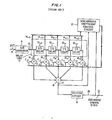
- FIG. 1 a typical conventional five-tap fractionally spaced equalizer also known as a "T/2" equalizer is shown.
- Delay elements 10 -2 ,10 -1 , 10+ 1 ,10 +2 of tapped delay line 11 must each provide signal delays of at least T'/2.
- T/2-delay elements is known to satisfy this requirement and also simplify the circuit realization of this apparatus.
- the analog-to- digital converter 9, which converts the time-varying spectrally shaped input signal x(f) on conductor 8 to a corresponding digital word on digital bus 13 is clocked at the T/2 rate.
- the equalizer operates, the output of converter 9 is shifted through each tapped delay line element every T/2 seconds.
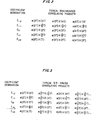
- FIG. 2 summarizes the types of products that would be used in performing the correlation of synchronous signals appropriate to adaptively controlling the coefficients of the fractionally spaced equalizer illustrated in F IG . 1. Observe that for any coefficient, consecutive error signals, e, and tapped delay line signals, x, are spaced by the symbol period T .
- the time-varying representation of a spectrally shaped digital signal with spectrum P(w) is where: s(t) is the baseband, timing-varying digital signal, the an are the transmitted symbol states (e.g., +1,+3 in a 4-level PCM digital signal), and p(t) is the inverse Fourier transform of P(m). Since fractionally spaced equalizers exemplified by the prior art provide estimates of an which are known to be predominantly correct, the continuous-time equalizer output is well approximated by where Pe(t) is the Nyquist impulse function we expect to see in the absence of digital signal corruption.
- Equation (3) is a function that decays rapidly with time. Therefore, y(t) can be accurately represented by truncating p e (t), which is tantamount to truncating the infinite summations in equations (3) and (4).
- This approach is very accurate, using relatively few terms in equation (3), for the synthesis of transmitted, spectrally-shaped digital signals).
- eT 0 ⁇ e ⁇ 1
- the appropriate fractional target is therefore Relative to estimated symbol â 0 , â with negative indices are previously estimated symbol states and a with positive indices are subsequent estimated symbol states.
- the number of terms selected in equation (5) obviously influences the accuracy of d f (eT).
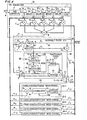
- FIG. 4 is a circuit diagram of a fractionally spaced equalizer embodying the inventive principles.
- the output of the equalizer on n-bit digital bus 17 is applied to switch 32 of integral-T error circuit 40 and switch 33 of fractional-T error circuit 48.
- Switches 32 and 33 which are realized by tristate devices, are respectively clocked at the T rate for terms corresponding to the occurrence of symbols, and the T rate for terms corresponding to the fractional symbol point, typically T/2 for "T/2" equalizers.
- switch 32 produces an output signal y i at the integral-T points
- switch 33 produces an output signal y f at the fractional-T time which appears on bus 55.
- the y i signal becomes an input of algebraic combiner 35.
- the other input to combiner 35 is provided by ROM 37 on bus 39 in response to the input y i .
- the output of ROM 37 corresponds to one of the a priori discrete transmission symbol levels, a. for a preselected range of digital input values in the y i signal. In our previous notation, this signal is designated d i .
- Combiner 35 produces an output'error signal e i on data bus 38 equal to the difference between the actual signal value and the estimated symbol state.
- the signal d i is also the desired output since after convergence of equalizer 30, e i will be minimized in a mean-squared sense. Hence y i approaches d i .
- a portion of the data on bus 39 is used to define â i on bus 41.
- m L .
- Delays 43 and 44 each have propagation delays corresponding to one symbol period so that their outputs are the previously estimated symbols.
- ROM 50 contains the time domain information that characterizes the desired Nyquist spectral shape at the receiver, and thus provides the appropriate fractional-T reference signal, d f , on data bus 51.
- â -1 , â 0 , and â 1 form a digital address to ROM 50 that calls forth a digital representation for target signal
- the output of ROM 50 is the input to resynchronizer 52 via bus 51.
- Resynchronizer 52 provides one input to algebraic signal combiner 54 while resynchronizer 53 provides the other input thereto.
- Switch 33 produces an output signal y f on data bus 55 as the input for resynchronizer 53.
- Resynchronizers 52 and 53 are clocked in unison by the T clock signal to provide concurrent inputs for combiner 54.
- the error signal on bus 60 is applied to multiplier 61 of correlator/coefficient word storage circuit 65-1.
- the other input to multiplier 61 comes from the tapped delay line of the fractionally spaced equalizer at node 14+2 of FIG. 1.
- the output of multiplier 61 on bus 62 alternately contains products of e and x like those appearing after C +2 in the last row of FIG. 3.
- Product terms on bus 62 enter accumulator 64, wherein a running sum is maintained. When accumulator 64 reaches a predetermined positive threshold, conductor 66 sends a decrement bit to up/down counter 67 and resets accumulator 64 to zero.
- accumulator 64 reaches a predetermined negative threshold, conductor 66 sends an increment bit to up/down counter 67 and also resets accumulator 64 to zero.
- Counter 67 contains coefficient C +2 of the fractionally spaced equalizer, and sends this digital word via bus 68 to multiplier 15 +2 in fractionally spaced equalizer 30.
- circuits 65-2, 65-3, 65-4 and 65-5 are identical to that of 65-1, with respective multiplier inputs coming in common from error signal bus 60 and individually from nodes 14 +1 .14 0' 14_1 and 14 -2 of the fractionally spaced equalizer.
- the coefficients generated by 65-2, 65-3, 65-4 and 65-5 are C +1 ,C 0 ,C -1 , and C -2 , respectively, and appear at multipliers 15 +1 ,15 0 , 15- 1 , and 15 -2 , respectively.
- quadrature ampitude modulated In many contemporary digital communication systems, transmission capacity is increased by the use of quadrature ampitude modulated (QAM) signaling.
- QAM quadrature ampitude modulated
- two independent multilevel data streams are modulated at the same frequency by time-orthogonal carriers and added together to form the passband transmitted signal.
- the composite signal is split into two parallel data streams and synchronously demodulated by quadrature carriers.
- the two received data streams are designated as the I -rail and Q -rail, and can be applied to an array of fractionally spaced equalizers for removal of linear distortion. This approach is illustrated in FIG. 5, where we show fractionally spaced equalizer array 70.
- Each fractionally spaced equalizer within array 70 - 70 1 , 70 2 , 70 3 and 70 4 - includes: a tapped delay line, tap weight multiplier circuits, a summer, and correlator/coefficient word storage circuits such as delay line 11, multipliers 15, summer 16, and Nyquist-rate correlator/coefficient word storage circuits 65, as illustrated in FIG. 4.
- the I-rail baseband input on data bus 67 is applied to equalizers 70 1 and 70 2
- the Q-rail input on data bus 68 is applied to equalizers 70 3 and 70 4
- the N yquist-rate outputs of equalizers 70 1 ,70 2 ,70 3 and 70 4 appear on digital buses 72, 73, 74 and 75, respectively.
- the signal on buses 72 and 74 are added by summer 77 with an output on bus 78. This signal is an input to integral-T error circuit 80 and fractional-T error circuit 81.
- Signals on data buses 73 and 75 are similarly added by summer 83 with output on data bus 84 applied as an input to both integral-T error circuit 86 and fractional-T error circuit 87.
- circuit 80 of FIG. 5 has two output signals: the estimated symbol state for the I-rail, â I , on bus 90; and a derived integral-T error signal for coefficient control, e i , I , on bus 92.
- fractional-T error circuit 48 in FIG. 4 shows that circuit 81 of FIG. 5 has one output signal: a derived fractional-T error signal for coefficient control, e f , I , on bus 94.
- 86 has outputs a Q on bus 96 and e i , Q on bus 98.
- circuit 87 has an output e f , Q on bus 100.
- the coefficients of equalizer 70 1 are controlled by correlating products like those illustrated in F IG . 3.
- Equalizer 70 therefore uses input buses 92 and 94 with signals along its tapped delay line (like 14 -2 , 14 -1 , 14 0 , 14 1 , 14 2 of FIG. 4) to perform the correlative products of FIG. 3 to update coefficients C -2 , C -1 , C 0 , C +1' C+ 2 of FIG. 1 using correlator/coefficient word storage circuits 65-1, 65-2, 65-3, 65-4, 65-5 like those of FIG. 4.
- the coefficients of equalizer 70 4 are controlled using input buses 98 and 100 with its own tapped delay line signals to perform the correlative products of FIG. 3.
- Equalizer 70 2 a cross-coupling equalizer, uses error signals e i , Q on bus 98 and e f ,Q on bus 100 for correlation with its own tapped delay line; equalizer 70 3r also a cross-coupling equalizer, uses error signals e i ,I on bus 92 and e f ,I on bus 94 for internal correlation with its tapped delay line signals.
- the tapped delay line signals of 70 1 are the same as those of 70 2 and that they can share a common tapped delay line.
- the tapped delay line signais of 70 3 and 70 4 are identical and they can share a common tapped delay line.
- fractionally spaced equalizers 30 of FIG. 4 and 70 1 , 70 2 , 70 3 , and 70 4 of FIG. 5 can be implemented at passband.
- the output signal is'then demodulated to baseband, where baseband error generation circuitry similar to error circuits 40 and 48 and to correlator/coefficient word storage circuits of FIG. 4 are used for coefficient adaptation.
- This error signal is invariably define as the difference between the equalizer output (y) and reference signals (d), the latter provided by either a training sequence or based on estimates from the equalizer output. If these reference signals are unavailable at the Nyquist rate, they can be generated from a weighted sequence of previous and subsequent estimated outputs. The estimated previous and subsequent outputs are digitally coded and address a ROM to call forth the a priori interpolative reference.
Landscapes
- Engineering & Computer Science (AREA)
- Power Engineering (AREA)
- Computer Networks & Wireless Communication (AREA)
- Signal Processing (AREA)
- Cable Transmission Systems, Equalization Of Radio And Reduction Of Echo (AREA)
- Filters That Use Time-Delay Elements (AREA)
Applications Claiming Priority (2)
| Application Number | Priority Date | Filing Date | Title |
|---|---|---|---|
| US06/552,415 US4550415A (en) | 1983-11-16 | 1983-11-16 | Fractionally spaced equalization using nyquist-rate coefficient updating |
| US552415 | 1983-11-16 |
Publications (2)
| Publication Number | Publication Date |
|---|---|
| EP0142144A2 true EP0142144A2 (de) | 1985-05-22 |
| EP0142144A3 EP0142144A3 (de) | 1988-03-16 |
Family
ID=24205241
Family Applications (1)
| Application Number | Title | Priority Date | Filing Date |
|---|---|---|---|
| EP84113572A Withdrawn EP0142144A3 (de) | 1983-11-16 | 1984-11-10 | Verteilt angeordnetes Entzerrungsverfahren und Entzerrer unter Anwendung von Koeffizienten-Aktualisierung mit Nyquistrat |
Country Status (4)
| Country | Link |
|---|---|
| US (1) | US4550415A (de) |
| EP (1) | EP0142144A3 (de) |
| JP (1) | JPS60120610A (de) |
| CA (1) | CA1221749A (de) |
Cited By (2)
| Publication number | Priority date | Publication date | Assignee | Title |
|---|---|---|---|---|
| FR2623669A1 (fr) * | 1987-11-19 | 1989-05-26 | American Telephone & Telegraph | Appareil et procede d'egalisation pour la transmission de donnees |
| EP0419225A3 (en) * | 1989-09-20 | 1992-03-18 | Fujitsu Limited | Transversal type automatic equalizer with tap coefficient protection |
Families Citing this family (60)
| Publication number | Priority date | Publication date | Assignee | Title |
|---|---|---|---|---|
| DE3345284A1 (de) * | 1983-12-14 | 1985-06-27 | Siemens AG, 1000 Berlin und 8000 München | Verfahren und schaltungsanordnung zur digitalsignalverarbeitung nach art eines vorzugsweise adaptiven transversalfilters |
| US4817025A (en) * | 1984-02-03 | 1989-03-28 | Sharp Kabushiki Kaisha | Digital filter |
| GB8406846D0 (en) * | 1984-03-16 | 1984-04-18 | British Telecomm | Digital filters |
| JPS61102813A (ja) * | 1984-10-25 | 1986-05-21 | Hitachi Denshi Ltd | 適応デイジタルフイルタ |
| AR241298A1 (es) * | 1985-10-03 | 1992-04-30 | Siemens Ag | Ecualizador transversal adaptivo . |
| JPS62104324A (ja) * | 1985-10-31 | 1987-05-14 | Toshiba Corp | 適応形自動等化器 |
| US4745622A (en) * | 1986-07-29 | 1988-05-17 | Integrated Network Corporation | Equalizer for digital transmission systems |
| US4887278A (en) * | 1986-07-29 | 1989-12-12 | Integrated Network Corporation | Equalizer for digital transmission systems |
| JP2531699B2 (ja) * | 1987-09-08 | 1996-09-04 | 株式会社日立製作所 | 波形等化方式及び装置 |
| GB8721159D0 (en) * | 1987-09-09 | 1987-10-14 | Philips Nv | Adjusting filter coefficients |
| US4856031A (en) * | 1988-04-28 | 1989-08-08 | General Datacomm, Inc. | Adaptive multiharmonic phase jitter compensation |
| US4899366A (en) * | 1988-08-02 | 1990-02-06 | International Business Machines Corporation | Tap rotation n fractionally spaced equalizer to compensate for drift due to fixed sample rate |
| US4995057A (en) * | 1988-11-02 | 1991-02-19 | At&T Bell Laboratories | Technique for achieving the theoretical coding gain of digital signals incorporating error correction |
| JPH0687540B2 (ja) * | 1988-11-10 | 1994-11-02 | 日本電気株式会社 | 復調装置 |
| DE3841268A1 (de) * | 1988-12-08 | 1990-06-13 | Thomson Brandt Gmbh | Digitales filter |
| DE3916236A1 (de) * | 1989-05-18 | 1990-11-22 | Ant Nachrichtentech | Digitalfilter mit daempfungs- und phasengangentzerrung |
| DE3916256A1 (de) * | 1989-05-18 | 1990-11-22 | Ant Nachrichtentech | Digitalfilter mit daempfungs- und phasengangentzerrung |
| US5008903A (en) * | 1989-05-25 | 1991-04-16 | A.T. & T. Paradyne | Adaptive transmit pre-emphasis for digital modem computed from noise spectrum |
| FR2650137B1 (de) * | 1989-07-18 | 1994-10-28 | France Etat | |
| GB2241855B (en) * | 1990-03-09 | 1994-03-23 | Otc Ltd | Improvements to adaptive equalisers |
| CA2073082C (en) * | 1991-07-08 | 1997-09-09 | Takanori Iwamatsu | Fractionally spaced cross-polarization interference canceller |
| US5249205A (en) * | 1991-09-03 | 1993-09-28 | General Electric Company | Order recursive lattice decision feedback equalization for digital cellular radio |
| JPH05183456A (ja) * | 1991-12-27 | 1993-07-23 | Nec Corp | 制御信号発生装置 |
| US5621769A (en) * | 1992-06-08 | 1997-04-15 | Novatel Communications Ltd. | Adaptive-sequence-estimation apparatus employing diversity combining/selection |
| US5416799A (en) * | 1992-08-10 | 1995-05-16 | Stanford Telecommunications, Inc. | Dynamically adaptive equalizer system and method |
| US5309484A (en) * | 1992-09-01 | 1994-05-03 | Motorola, Inc. | Method and apparatus for asynchronous timing recovery using interpolation filter |
| US5559830A (en) * | 1995-01-23 | 1996-09-24 | Xetron Corp. | Equalization system for AM compatible digital receiver |
| IT1273963B (it) * | 1995-02-24 | 1997-07-11 | Alcatel Italia | Metodo e circuiti di equalizzazione a spaziatura frazionata |
| USH2015H1 (en) | 1995-03-31 | 2002-03-05 | The United States Of America As Represented By The Secretary Of The Navy | Communications system using a sharply bandlimited keying waveform |
| US5809065A (en) * | 1996-02-20 | 1998-09-15 | Usa Digital Radio Partners, L.P. | Method and apparatus for improving the quality of AM compatible digital broadcast system signals in the presence of distortion |
| US5898732A (en) * | 1996-02-20 | 1999-04-27 | Usa Digital Radio Partners, L.P. | Data service channel provision for an AM compatible broadcast system |
| US5703954A (en) * | 1996-02-20 | 1997-12-30 | Usa Digital Radio Partners, L.P. | Method and apparatus for improving the quality of AM compatible digital broadcast system signals in the presence of distortion |
| US5930687A (en) * | 1996-09-30 | 1999-07-27 | Usa Digital Radio Partners, L.P. | Apparatus and method for generating an AM-compatible digital broadcast waveform |
| US7190720B2 (en) * | 2001-07-03 | 2007-03-13 | Zenith Electronics Corporation | Tap weight initializer for an adaptive equalizer |
| US6128334A (en) * | 1997-02-21 | 2000-10-03 | Usa Digital Radio, Inc. | Receiver addressable AM compatible digital broadcast system |
| US5878089A (en) * | 1997-02-21 | 1999-03-02 | Usa Digital Radio Partners, L.P. | Coherent signal detector for AM-compatible digital audio broadcast waveform recovery |
| US6009446A (en) * | 1998-02-04 | 1999-12-28 | Lsi Logic Corporation | Method and apparatus for digital filtration of signals |
| US6377642B1 (en) | 1999-02-26 | 2002-04-23 | Cisco Technologies, Inc. | System for clock recovery |
| CA2332609A1 (en) * | 2001-01-29 | 2002-07-29 | Silicon Analog Systems Corporation | High speed filter |
| US7830956B2 (en) * | 2003-02-05 | 2010-11-09 | Fujitsu Limited | Method and system for processing a sampled signal |
| US7324589B2 (en) * | 2003-02-05 | 2008-01-29 | Fujitsu Limited | Method and system for providing error compensation to a signal using feedback control |
| US7289555B2 (en) * | 2003-02-05 | 2007-10-30 | Fujitsu Limited | Method and system for signal processing using vector output from scalar data |
| US7301998B2 (en) * | 2003-12-19 | 2007-11-27 | Intel Corporation | Filter with signal taps temporally spaced at fractional symbol intervals |
| US8041233B2 (en) * | 2004-07-14 | 2011-10-18 | Fundación Tarpuy | Adaptive equalization in coherent fiber optic communication |
| US7738546B2 (en) * | 2004-09-27 | 2010-06-15 | Intel Corporation | Feed forward equalizer for a communication system |
| US7551667B2 (en) * | 2004-09-27 | 2009-06-23 | Intel Corporation | Feed forward equalizer |
| US7596176B2 (en) * | 2005-10-31 | 2009-09-29 | International Business Machines Corporation | Apparatus, system, and method for adaptive asynchronous equalization using leakage |
| KR20070114557A (ko) * | 2006-05-29 | 2007-12-04 | 삼성전자주식회사 | 퓨즈를 갖는 반도체 기억 소자 및 그 형성 방법 |
| US7839958B2 (en) | 2006-05-30 | 2010-11-23 | Fujitsu Limited | System and method for the adjustment of compensation applied to a signal |
| US7764757B2 (en) * | 2006-05-30 | 2010-07-27 | Fujitsu Limited | System and method for the adjustment of offset compensation applied to a signal |
| US7817757B2 (en) * | 2006-05-30 | 2010-10-19 | Fujitsu Limited | System and method for independently adjusting multiple offset compensations applied to a signal |
| US7804921B2 (en) | 2006-05-30 | 2010-09-28 | Fujitsu Limited | System and method for decoupling multiple control loops |
| US7787534B2 (en) * | 2006-05-30 | 2010-08-31 | Fujitsu Limited | System and method for adjusting offset compensation applied to a signal |
| US7839955B2 (en) * | 2006-05-30 | 2010-11-23 | Fujitsu Limited | System and method for the non-linear adjustment of compensation applied to a signal |
| US7801208B2 (en) * | 2006-05-30 | 2010-09-21 | Fujitsu Limited | System and method for adjusting compensation applied to a signal using filter patterns |
| US7817712B2 (en) * | 2006-05-30 | 2010-10-19 | Fujitsu Limited | System and method for independently adjusting multiple compensations applied to a signal |
| US7760798B2 (en) * | 2006-05-30 | 2010-07-20 | Fujitsu Limited | System and method for adjusting compensation applied to a signal |
| US7848470B2 (en) * | 2006-05-30 | 2010-12-07 | Fujitsu Limited | System and method for asymmetrically adjusting compensation applied to a signal |
| US7804894B2 (en) | 2006-05-30 | 2010-09-28 | Fujitsu Limited | System and method for the adjustment of compensation applied to a signal using filter patterns |
| US8514012B2 (en) * | 2011-05-17 | 2013-08-20 | Nxp B.V. | Pulse shaper circuit with reduced electromagnetic emission |
Family Cites Families (7)
| Publication number | Priority date | Publication date | Assignee | Title |
|---|---|---|---|---|
| JPS5927133B2 (ja) * | 1979-02-21 | 1984-07-03 | 日本電気株式会社 | 適応型受信機 |
| US4237554A (en) * | 1979-03-01 | 1980-12-02 | Bell Telephone Laboratories, Incorporated | Coefficient tap leakage for fractionally-spaced equalizers |
| US4384355A (en) * | 1979-10-15 | 1983-05-17 | Bell Telephone Laboratories, Incorporated | Control of coefficient drift for fractionally spaced equalizers |
| US4320526A (en) * | 1980-03-03 | 1982-03-16 | Bell Telephone Laboratories, Incorporated | Adaptive phase-jitter tracker |
| EP0048475B1 (de) * | 1980-09-24 | 1986-01-22 | Kabushiki Kaisha Toshiba | Transversalentzerrer |
| US4343759A (en) * | 1980-10-10 | 1982-08-10 | Bell Telephone Laboratories, Incorporated | Equalizer section |
| US4376308A (en) * | 1981-04-01 | 1983-03-08 | Bell Telephone Laboratories, Incorporated | Control of coefficient drift for fractionally spaced equalizers |
-
1983
- 1983-11-16 US US06/552,415 patent/US4550415A/en not_active Expired - Lifetime
-
1984
- 1984-10-23 CA CA000466137A patent/CA1221749A/en not_active Expired
- 1984-11-10 EP EP84113572A patent/EP0142144A3/de not_active Withdrawn
- 1984-11-16 JP JP59242223A patent/JPS60120610A/ja active Pending
Non-Patent Citations (1)
| Title |
|---|
| ICC'71 CIC, PROCEEDINGS OF THE IEEE INTERNATIONAL CONFERENCE ON COMMUNICATIONS, Montreal, 14th-16th June 1971, pages 38-12 - 38-17; W.M. COWAN et al.: "Automatic telephone line equalization" * |
Cited By (2)
| Publication number | Priority date | Publication date | Assignee | Title |
|---|---|---|---|---|
| FR2623669A1 (fr) * | 1987-11-19 | 1989-05-26 | American Telephone & Telegraph | Appareil et procede d'egalisation pour la transmission de donnees |
| EP0419225A3 (en) * | 1989-09-20 | 1992-03-18 | Fujitsu Limited | Transversal type automatic equalizer with tap coefficient protection |
Also Published As
| Publication number | Publication date |
|---|---|
| JPS60120610A (ja) | 1985-06-28 |
| EP0142144A3 (de) | 1988-03-16 |
| CA1221749A (en) | 1987-05-12 |
| US4550415A (en) | 1985-10-29 |
Similar Documents
| Publication | Publication Date | Title |
|---|---|---|
| US4550415A (en) | Fractionally spaced equalization using nyquist-rate coefficient updating | |
| US4789994A (en) | Adaptive equalizer using precursor error signal for convergence control | |
| US5285482A (en) | Timing recovery device for receiver installation using adaptive equalization and oversampling associated with differentially coherent demodulation | |
| CA2044261C (en) | A method of adapting a viterbi algorithm to a channel having varying transmission properties, and apparatus for carrying out the method | |
| US5119401A (en) | Decision feedback equalizer including forward part whose signal reference point is shiftable depending on channel response | |
| US5020078A (en) | Baudrate timing recovery technique | |
| JPS58501977A (ja) | 干渉相殺法と装置 | |
| US5050186A (en) | Signal equalizing arrangement and a method of equalizing a received data signal | |
| US5111484A (en) | Adaptive distortion canceller | |
| CN1082279A (zh) | 一种在数字信号传输的接收机中估计所传输的符号的方法和设备 | |
| Mueller et al. | Cyclic equalization—A new rapidly converging equalization technique for synchronous data communication | |
| US7224725B2 (en) | Method for determining coefficients of an equalizer and apparatus for determining the same | |
| EP0050930B1 (de) | Datenübertragung | |
| US5267265A (en) | Decision feedback equalizer with expansion and decision circuit | |
| CN113973033B (zh) | 具有基于扰动影响的自适应的均衡器 | |
| US5406589A (en) | Fractionally spaced cross-polarization interference canceller | |
| US7242712B1 (en) | Decision feedback equalizer (DFE) for jitter reduction | |
| JP3251023B2 (ja) | 自動等化器 | |
| US7177352B1 (en) | Pre-cursor inter-symbol interference cancellation | |
| Clark et al. | Near-maximum-likelihood detection processes for distorted digital signals | |
| Clark et al. | Pseudobinary and pseudoquaternary detection processes for linearly distorted multilevel QAM signals | |
| CN114374587B (zh) | 基于帧的信道时域均衡方法 | |
| US8937995B2 (en) | Equalizer and equalizing method thereof | |
| US8644369B1 (en) | Equalizer adaptation for heavily compressed or clipped communications signals | |
| Singh et al. | Approaches to Channel Equalization |
Legal Events
| Date | Code | Title | Description |
|---|---|---|---|
| PUAI | Public reference made under article 153(3) epc to a published international application that has entered the european phase |
Free format text: ORIGINAL CODE: 0009012 |
|
| AK | Designated contracting states |
Designated state(s): FR GB IT NL |
|
| PUAL | Search report despatched |
Free format text: ORIGINAL CODE: 0009013 |
|
| AK | Designated contracting states |
Kind code of ref document: A3 Designated state(s): FR GB IT NL |
|
| 17P | Request for examination filed |
Effective date: 19880910 |
|
| 17Q | First examination report despatched |
Effective date: 19891025 |
|
| STAA | Information on the status of an ep patent application or granted ep patent |
Free format text: STATUS: THE APPLICATION IS DEEMED TO BE WITHDRAWN |
|
| 18D | Application deemed to be withdrawn |
Effective date: 19900507 |
|
| RIN1 | Information on inventor provided before grant (corrected) |
Inventor name: SILLER, CURTIS A., JR. Inventor name: DEBUS, WALTER, JR. |