EP0142175A2 - Zündspule für einen Verbrennungsmotor - Google Patents
Zündspule für einen Verbrennungsmotor Download PDFInfo
- Publication number
- EP0142175A2 EP0142175A2 EP84113870A EP84113870A EP0142175A2 EP 0142175 A2 EP0142175 A2 EP 0142175A2 EP 84113870 A EP84113870 A EP 84113870A EP 84113870 A EP84113870 A EP 84113870A EP 0142175 A2 EP0142175 A2 EP 0142175A2
- Authority
- EP
- European Patent Office
- Prior art keywords
- winding
- ignition coil
- bobbin
- turns
- set forth
- Prior art date
- Legal status (The legal status is an assumption and is not a legal conclusion. Google has not performed a legal analysis and makes no representation as to the accuracy of the status listed.)
- Withdrawn
Links
- 238000002485 combustion reaction Methods 0.000 title claims abstract description 6
- 238000004804 winding Methods 0.000 claims abstract description 124
- XEEYBQQBJWHFJM-UHFFFAOYSA-N Iron Chemical group [Fe] XEEYBQQBJWHFJM-UHFFFAOYSA-N 0.000 claims description 6
- 229920005989 resin Polymers 0.000 claims description 6
- 239000011347 resin Substances 0.000 claims description 6
- 230000002093 peripheral effect Effects 0.000 claims description 3
- 230000007423 decrease Effects 0.000 claims description 2
- 238000000034 method Methods 0.000 description 5
- 229920003002 synthetic resin Polymers 0.000 description 4
- 239000000057 synthetic resin Substances 0.000 description 4
- 238000004519 manufacturing process Methods 0.000 description 3
- RTZKZFJDLAIYFH-UHFFFAOYSA-N Diethyl ether Chemical compound CCOCC RTZKZFJDLAIYFH-UHFFFAOYSA-N 0.000 description 2
- 238000010276 construction Methods 0.000 description 2
- 230000003247 decreasing effect Effects 0.000 description 1
- 150000002505 iron Chemical class 0.000 description 1
- 229910052742 iron Inorganic materials 0.000 description 1
- 239000000463 material Substances 0.000 description 1
- 238000000465 moulding Methods 0.000 description 1
Images


Classifications
-
- H—ELECTRICITY
- H01—ELECTRIC ELEMENTS
- H01F—MAGNETS; INDUCTANCES; TRANSFORMERS; SELECTION OF MATERIALS FOR THEIR MAGNETIC PROPERTIES
- H01F27/00—Details of transformers or inductances, in general
- H01F27/28—Coils; Windings; Conductive connections
- H01F27/2823—Wires
-
- H—ELECTRICITY
- H01—ELECTRIC ELEMENTS
- H01F—MAGNETS; INDUCTANCES; TRANSFORMERS; SELECTION OF MATERIALS FOR THEIR MAGNETIC PROPERTIES
- H01F38/00—Adaptations of transformers or inductances for specific applications or functions
- H01F38/12—Ignition, e.g. for IC engines
-
- H—ELECTRICITY
- H01—ELECTRIC ELEMENTS
- H01F—MAGNETS; INDUCTANCES; TRANSFORMERS; SELECTION OF MATERIALS FOR THEIR MAGNETIC PROPERTIES
- H01F5/00—Coils
- H01F5/02—Coils wound on non-magnetic supports, e.g. formers
-
- H—ELECTRICITY
- H01—ELECTRIC ELEMENTS
- H01F—MAGNETS; INDUCTANCES; TRANSFORMERS; SELECTION OF MATERIALS FOR THEIR MAGNETIC PROPERTIES
- H01F27/00—Details of transformers or inductances, in general
- H01F27/28—Coils; Windings; Conductive connections
- H01F27/2823—Wires
- H01F2027/2842—Wire coils wound in conical zigzag to reduce voltage between winding turns
Definitions
- the present invention relates to an ignition coil for an internal combustion engine, and more particularly relates to a secondary bobbin on which a secondary winding is wound.
- a secondary bobbin is formed with a plurality of axially spaced ribs between a pair of flanges formed at both ends thereof for providing a plurality of winding grooves defined therebetween and a secondary winding is wound in series within each groove.
- a wire is so wound therein that a certain number of continuous winding turns are laterally arranged to form one winding layer and another number of winding turns are likewise laterally arranged on the outer periphery of the winding layer.
- the next winding layer is formed in the next groove so that the total number of winding turns in one groove is reduced to a small number in order to ensure a dielectric strength between wires of winding turns and winding layers.
- the dielectric strength is also ensured by covering material coated on the wire, an insulating synthetic resin filled in a casing of the ignition coil and the plurality of ribs.
- the above-explained conventional secondary-bobbin of the divided type is however inevitably high in cost since it should be manufactured with a great precision so as to prevent a disconnection of the secondary winding, which may be caused by a burr, a stepped portion or the like formed during a-molding step of the secondary bobbin. And further the conventional secondary bobbin is larger in size by the volume of the ribs defining the grooves.
- a secondary bobbin of the ignition coil is formed with a pair of flanges at its both ends and a plurality of ribs are removed to form a single wide groove, within which a secondary winding is wound.
- a wire is so wound in the single groove of the secondary bobbin that a certain number of continuous winding turns form a winding layer of a truncated conical configuration and other winding layers of the same configuration are formed one on the other and axially arranged to form a secondary winding.
- a number of winding turns for each winding layer is increased in sequence to the certain number at a beginning portion of the winding as the wire is wound, while a.number of winding turns for each winding layer is decreased in sequence to zero at an ending portion of the winding.
- numeral 1 designates an iron core made of laminated iron plates, both ends of which are projecting outwardly from a resin casing 7.
- a primary bobbin 2 made of insulating synthetic resin is fixed to the iron core 1 and disposed in a central portion of the casing 7.
- a secondary bobbin 4 made of insulating synthetic resin is formed with a pair of flanges 4a at its both ends and is disposed outside of and concentrically of the primary bobbin 2 in the casing 7.
- a primary and a secondary windings 3 and 5 are respectively wound on the primary and secondary bobbins 2 and 4 and an insulating resin 6 is filled within the casing 7.
- a cap 8 made of insulating resin is attached to an open end of the casing 7 to enclose therein the primary and secondary windings.
- a first connector portion 8a of a rectangular shape and a second connector portion 8b of an annular shape are integrally formed with the cap 8, a pair of primary terminals 9 and 10 are inserted into the first connector portion 8a and a secondary terminal 12 is inserted into the second connector portion 8b.
- One end of the primary winding 3 as well as one end of the secondary winding 5 is soldered to an inside end 9a of the terminal 9, an outside end of which is to be connected to a battery (not shown) mounted on a motor vehicle.
- the other end of the primary winding 3 is soldered to an inside end of the terminal 10, an outside end of which is to be connected to a contact point (not shown) of a contact-type ignition distributor or to a power transistor (not shown) of a contactless ignition system.
- the other end of the secondary winding 5 is soldered to an inside end 12a of the terminal 12, an outside end of which is to be connected to a center electrode (not shown) of a distributor cap or to a spark plug (not shown).
- An insulated wire is wound within a single wide groove 4b defined by and between the pair of flanges 4a as in the following manner.
- a first winding turn of the wire is at first wound at an inside corner of a groove end, then a second winding turn is wound beside the first winding turn and the following winding turns are continuously and in sequence wound adjoining each other.
- the first and the second winding turns form a first winding layer having a sloping surface of a truncated conical configuration.
- the following certain number of winding turns are wound on the sloping surface of the first winding layer to thereby form a second winding layer having also a sloping surface of that configuration.
- a plurality of winding layers are formed lying one upon another, and until a winding layer reaches at a predetermined height in the groove the number of winding turns for each winding layer increases and thereafter the number of winding turns of one layer is kept at a constant number so that the height of the secondary winding 5 is made substantially equal over its axial width.
- the number of winding turns for each winding layer decreases in sequence at the ether groove end.
- An angle of the sloping surface with respect to a longitudinal axis of the bobbin is preferably round 30° in order to keep its sloping shape during a winding process.
- the number (N indicated in Fig. 3) of the winding turns for each winding layer at an intermediate portion of the secondary winding is, for example, so selected to be substantially the same as that number, the winding turns of which are wound in a groove of a prior art divided type bobbin to form one winding layer.
- the dielectric strength between the every adjacent winding layers can be satisfactorily ensured without providing any ribs for dividing the groove into a plurality of small grooves. And since the number of winding turns of one winding layer at the beginning and the ending portions is smaller than that at the intermediate portion, the dielectric strength between the adjacent winding turns as well as between the adjacent winding layers can be also surely ensured, although the potential gradient at the winding ends of the ignition coil secondary winding is higher than that at the intermediate portion thereof.
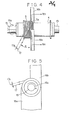
- the secondary bobbin 4 is attached to shafts 15 of a winding machine and rotated thereby in a direction of an arrow 15a indicated in the drawings.
- a wire 17 is held by a winding nozzle (not shown) and pulled leftwardly in Fig. 4 with an angleewith respect to a plane perpendicular to the longitudinal axis of the secondary bobbin 4.
- the winding nozzle is reciprocated in a direction indicated by an arrow 17a and this reciprocating movement is moved from the lefthand side (the beginning portion of the winding) to the righthand side (the ending portion of the winding) as indicated by an arrow 14 in Fig.
- a winding sloping surface 5a of the secondary winding is pressed in a radial direction by a pair of guide members 16a and 16b (as best shown in Fig. 6) made of felt or the like so as to keep its shape and the guide members are moved towards the ending side as indicated by an arrow 16c in accordance with the winding process.
- the wire 17 can not be pulled leftwardly with the angle of because the flange 4a is formed at the end of the bobbin 4, and thereby the wire 17 is pulled outwardly and radially at the beginning portion.
- Some winding turns at this portion are, therefore, likely to go out of its truncated conical shape.
- the sloping surface of the winding can not be pressed radially by the guide members 16a and 16b at the ending portion of the winding because the flange 4a is also formed at the other end of the bobbin. Some winding turns at this portion are, therefore, likely to go out of its shape.
- the shape of the widing turns or the winding layers at the beginning or ending portion may not cause a problem, even when the shape is somewhat out of the desired truncated conical shape.
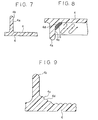
- Figs. 7 to 9 show modified construction of the secondary bobbin, which prevents the winding turns from going out of shape and to facilitate the winding operation at the beginning portion.
- a modified secondary bobbin shown in Fig. 7 is formed with a spiral guiding groove 4c on the outer peripheral surface of the bobbin so that the winding turns are received in the grooves 4c and are prevented from going out of shape.
- a modified secondary bobbin shown in Fig. 8 is formed with a sloping surface 4d at the beginning corner of the bobbin to facilitate the winding process at this beginning portion.
- a modified secondary bobbin shown in Fig. 9 is formed with a sloping surface as in Fig. 7 and a spiral guiding groove on the sloping surface as well as the outer peripheral surface of the bobbin as in Fig. 6.
- a diameter of the ignition coil can be reduced by 10% and the whole volume of the ignition coil can be reduced to by 15% in comparison with the prior art divided type bobbin.
- the invention is explained which is applied to the ignition coil, the secondary winding 5 of which is disposed outside of the primary winding 3, however, the present invention can be also applied to an ignition coil, wherein a secondary winding is disposed inside of a primary winding.
- the present invention is applied to the ignition coil of the type wherein the insulating synthetic resin 6 is filled in the resin casing 7, the present invention can be applied to such an ignition coil of the type, according to which an insulating oil is filled within an iron casing.
Landscapes
- Engineering & Computer Science (AREA)
- Power Engineering (AREA)
- Ignition Installations For Internal Combustion Engines (AREA)
- Coils Of Transformers For General Uses (AREA)
Applications Claiming Priority (2)
| Application Number | Priority Date | Filing Date | Title |
|---|---|---|---|
| JP58216580A JPS60107813A (ja) | 1983-11-17 | 1983-11-17 | 点火コイル |
| JP216580/83 | 1983-11-17 |
Publications (2)
| Publication Number | Publication Date |
|---|---|
| EP0142175A2 true EP0142175A2 (de) | 1985-05-22 |
| EP0142175A3 EP0142175A3 (de) | 1985-07-10 |
Family
ID=16690639
Family Applications (1)
| Application Number | Title | Priority Date | Filing Date |
|---|---|---|---|
| EP84113870A Withdrawn EP0142175A3 (de) | 1983-11-17 | 1984-11-16 | Zündspule für einen Verbrennungsmotor |
Country Status (2)
| Country | Link |
|---|---|
| EP (1) | EP0142175A3 (de) |
| JP (1) | JPS60107813A (de) |
Cited By (10)
| Publication number | Priority date | Publication date | Assignee | Title |
|---|---|---|---|---|
| EP0253494A1 (de) * | 1986-07-09 | 1988-01-20 | Marshall Electric Corporation | Wickelkörper für Hochspannungstransformator |
| EP0762445A3 (de) * | 1995-08-25 | 1997-04-09 | Nippon Denso Co | |
| FR2740260A1 (fr) * | 1995-10-20 | 1997-04-25 | Paucher Aime | Bobinage electrique a faible difference de potentiel entre spires adjacentes |
| WO1998006114A1 (fr) * | 1996-08-07 | 1998-02-12 | Sagem S.A. | Bobinage, notamment pour circuit haute tension de bobine d'allumage |
| FR2762442A1 (fr) * | 1997-04-17 | 1998-10-23 | Electricfil | Bobine d'allumage pour l'alimentation d'une bougie de moteur thermique |
| EP0827164A3 (de) * | 1996-08-31 | 1998-11-18 | Toyo Denso Kabushiki Kaisha | Zündspulenvorrichtung für Brennkraftmaschine und Verfahren zum Wickeln einer Zündspule |
| EP0860840A3 (de) * | 1997-02-19 | 1998-11-25 | Toyo Denso Kabushiki Kaisha | Lagenwickelnverfahren für Zündspule |
| EP0860841A3 (de) * | 1997-02-19 | 1998-11-25 | Toyo Denso Kabushiki Kaisha | Lagenwickelnverfahren für Zündspule |
| EP0887547A1 (de) * | 1997-06-27 | 1998-12-30 | Cooper Industries Italia S.p.A. | Spule mit horizontalen Sekundärwicklungen |
| EP0898289A3 (de) * | 1997-08-07 | 2000-09-27 | Sumitomo Wiring Systems, Ltd. | Zündspule mit Ringmagnet |
Families Citing this family (3)
| Publication number | Priority date | Publication date | Assignee | Title |
|---|---|---|---|---|
| DE69625390T3 (de) * | 1995-06-19 | 2009-11-26 | DENSO CORPORATION, Kariya-shi | Elektromagnetspule |
| DE69706494T2 (de) * | 1996-08-31 | 2002-04-18 | Toyo Denso K.K., Tokio/Tokyo | Zündspulenvorrichtung für Brennkraftmaschine |
| JP5887852B2 (ja) * | 2011-11-14 | 2016-03-16 | 株式会社デンソー | 内燃機関用点火コイル及びその製造方法 |
Family Cites Families (3)
| Publication number | Priority date | Publication date | Assignee | Title |
|---|---|---|---|---|
| CH196451A (de) * | 1936-05-27 | 1938-03-15 | Jakob Bohli | Hochspannungsspule. |
| US3236937A (en) * | 1963-04-29 | 1966-02-22 | Briggs & Stratton Corp | Connector means and receptacle for connecting high tension lead to ignition coil |
| DE2405383A1 (de) * | 1974-02-05 | 1975-08-07 | Bosch Gmbh Robert | Spulentragkoerper fuer relais |
-
1983
- 1983-11-17 JP JP58216580A patent/JPS60107813A/ja active Pending
-
1984
- 1984-11-16 EP EP84113870A patent/EP0142175A3/de not_active Withdrawn
Cited By (15)
| Publication number | Priority date | Publication date | Assignee | Title |
|---|---|---|---|---|
| EP0253494A1 (de) * | 1986-07-09 | 1988-01-20 | Marshall Electric Corporation | Wickelkörper für Hochspannungstransformator |
| US6060973A (en) * | 1995-08-25 | 2000-05-09 | Nippondenso Co., Ltd. | Slant winding electromagnetic coil and ignition coil for internal combustion engine using same |
| EP0762445A3 (de) * | 1995-08-25 | 1997-04-09 | Nippon Denso Co | |
| US6252483B1 (en) | 1995-08-25 | 2001-06-26 | Nippondenso Co., Ltd. | Slant winding electromagnetic coil and ignition coil for internal combustion engine using same |
| FR2740260A1 (fr) * | 1995-10-20 | 1997-04-25 | Paucher Aime | Bobinage electrique a faible difference de potentiel entre spires adjacentes |
| WO1998006114A1 (fr) * | 1996-08-07 | 1998-02-12 | Sagem S.A. | Bobinage, notamment pour circuit haute tension de bobine d'allumage |
| FR2752328A1 (fr) * | 1996-08-07 | 1998-02-13 | Sagem | Bobinage, notamment pour circuit haute tension de bobine d'allumage |
| EA001459B1 (ru) * | 1996-08-07 | 2001-04-23 | Сажем С.А. | Способ намотки высоковольтной обмотки катушки зажигания |
| EP0827164A3 (de) * | 1996-08-31 | 1998-11-18 | Toyo Denso Kabushiki Kaisha | Zündspulenvorrichtung für Brennkraftmaschine und Verfahren zum Wickeln einer Zündspule |
| EP0860841A3 (de) * | 1997-02-19 | 1998-11-25 | Toyo Denso Kabushiki Kaisha | Lagenwickelnverfahren für Zündspule |
| EP0860840A3 (de) * | 1997-02-19 | 1998-11-25 | Toyo Denso Kabushiki Kaisha | Lagenwickelnverfahren für Zündspule |
| CN1101051C (zh) * | 1997-02-19 | 2003-02-05 | 东洋电装株式会社 | 点火线圈的迭绕装置 |
| FR2762442A1 (fr) * | 1997-04-17 | 1998-10-23 | Electricfil | Bobine d'allumage pour l'alimentation d'une bougie de moteur thermique |
| EP0887547A1 (de) * | 1997-06-27 | 1998-12-30 | Cooper Industries Italia S.p.A. | Spule mit horizontalen Sekundärwicklungen |
| EP0898289A3 (de) * | 1997-08-07 | 2000-09-27 | Sumitomo Wiring Systems, Ltd. | Zündspule mit Ringmagnet |
Also Published As
| Publication number | Publication date |
|---|---|
| EP0142175A3 (de) | 1985-07-10 |
| JPS60107813A (ja) | 1985-06-13 |
Similar Documents
| Publication | Publication Date | Title |
|---|---|---|
| EP1003185B2 (de) | Elektromagnetspule | |
| US5182537A (en) | Transformer with twisted conductors | |
| US6300857B1 (en) | Insulating toroid cores and windings | |
| US4639707A (en) | Transformer with toroidal magnetic core | |
| US5167063A (en) | Method of making a transformer winding in the form of a disc winding provided with axial channels | |
| US6252483B1 (en) | Slant winding electromagnetic coil and ignition coil for internal combustion engine using same | |
| US4985984A (en) | Ignition coil for internal combustion engine | |
| KR970005224B1 (ko) | 코일 어셈블리 | |
| US3461414A (en) | Inductive coil and method of making the same | |
| KR100206356B1 (ko) | 전동기용 계자코일의 제조방법 | |
| EP0253494B1 (de) | Wickelkörper für Hochspannungstransformator | |
| JPH0969455A (ja) | 電磁コイルおよびその製造装置 | |
| JPH0334643B2 (de) | ||
| JPH0219940Y2 (de) | ||
| JPS6050906A (ja) | 内燃機関用点火コイル | |
| JP4400613B2 (ja) | 電磁コイル | |
| JP4192834B2 (ja) | 電磁コイルの製造方法及びその装置 | |
| EP4618114A1 (de) | Spule und magnetische komponente | |
| US6483410B2 (en) | Ignition coil for motor vehicles | |
| JPH043475Y2 (de) | ||
| JPH07130559A (ja) | 自動車用点火コイル | |
| JPH02194507A (ja) | 小形電気巻線部品 | |
| JPS6317218Y2 (de) | ||
| JP3341755B2 (ja) | 電磁コイルおよびそれを用いた内燃機関用点火コイル | |
| JPS5934105Y2 (ja) | 分割巻形点火コイル |
Legal Events
| Date | Code | Title | Description |
|---|---|---|---|
| PUAI | Public reference made under article 153(3) epc to a published international application that has entered the european phase |
Free format text: ORIGINAL CODE: 0009012 |
|
| PUAL | Search report despatched |
Free format text: ORIGINAL CODE: 0009013 |
|
| AK | Designated contracting states |
Designated state(s): DE FR GB |
|
| AK | Designated contracting states |
Designated state(s): DE FR GB |
|
| STAA | Information on the status of an ep patent application or granted ep patent |
Free format text: STATUS: THE APPLICATION IS DEEMED TO BE WITHDRAWN |
|
| 18D | Application deemed to be withdrawn |
Effective date: 19860311 |
|
| RIN1 | Information on inventor provided before grant (corrected) |
Inventor name: TAKAKUWA, EIJI Inventor name: YAGI, YOSHIKAZU |