EP0142211A2 - Moteur électrique avec un dispositif d'amortissement - Google Patents
Moteur électrique avec un dispositif d'amortissement Download PDFInfo
- Publication number
- EP0142211A2 EP0142211A2 EP84201632A EP84201632A EP0142211A2 EP 0142211 A2 EP0142211 A2 EP 0142211A2 EP 84201632 A EP84201632 A EP 84201632A EP 84201632 A EP84201632 A EP 84201632A EP 0142211 A2 EP0142211 A2 EP 0142211A2
- Authority
- EP
- European Patent Office
- Prior art keywords
- motor
- damping mass
- rotor
- stop
- magnetic
- Prior art date
- Legal status (The legal status is an assumption and is not a legal conclusion. Google has not performed a legal analysis and makes no representation as to the accuracy of the status listed.)
- Granted
Links
- 238000013016 damping Methods 0.000 title claims abstract description 73
- 239000000463 material Substances 0.000 claims abstract description 16
- 230000005284 excitation Effects 0.000 claims description 10
- 230000009471 action Effects 0.000 claims description 6
- 239000000314 lubricant Substances 0.000 claims description 5
- XEEYBQQBJWHFJM-UHFFFAOYSA-N Iron Chemical compound [Fe] XEEYBQQBJWHFJM-UHFFFAOYSA-N 0.000 description 8
- 229910052742 iron Inorganic materials 0.000 description 4
- 230000001360 synchronised effect Effects 0.000 description 4
- 229910001369 Brass Inorganic materials 0.000 description 3
- 239000010951 brass Substances 0.000 description 3
- 238000010276 construction Methods 0.000 description 3
- 230000000087 stabilizing effect Effects 0.000 description 3
- 206010001497 Agitation Diseases 0.000 description 2
- 230000000694 effects Effects 0.000 description 2
- 230000006872 improvement Effects 0.000 description 2
- 239000003921 oil Substances 0.000 description 2
- 238000004804 winding Methods 0.000 description 2
- OPFJDXRVMFKJJO-ZHHKINOHSA-N N-{[3-(2-benzamido-4-methyl-1,3-thiazol-5-yl)-pyrazol-5-yl]carbonyl}-G-dR-G-dD-dD-dD-NH2 Chemical compound S1C(C=2NN=C(C=2)C(=O)NCC(=O)N[C@H](CCCN=C(N)N)C(=O)NCC(=O)N[C@H](CC(O)=O)C(=O)N[C@H](CC(O)=O)C(=O)N[C@H](CC(O)=O)C(N)=O)=C(C)N=C1NC(=O)C1=CC=CC=C1 OPFJDXRVMFKJJO-ZHHKINOHSA-N 0.000 description 1
- 238000004026 adhesive bonding Methods 0.000 description 1
- 230000008901 benefit Effects 0.000 description 1
- 230000015572 biosynthetic process Effects 0.000 description 1
- 229940126086 compound 21 Drugs 0.000 description 1
- 230000008878 coupling Effects 0.000 description 1
- 238000010168 coupling process Methods 0.000 description 1
- 238000005859 coupling reaction Methods 0.000 description 1
- 239000003925 fat Substances 0.000 description 1
- 230000002349 favourable effect Effects 0.000 description 1
- 239000012530 fluid Substances 0.000 description 1
- 238000009413 insulation Methods 0.000 description 1
- 230000003993 interaction Effects 0.000 description 1
- 230000005415 magnetization Effects 0.000 description 1
- 239000000203 mixture Substances 0.000 description 1
- 230000004048 modification Effects 0.000 description 1
- 238000012986 modification Methods 0.000 description 1
- 230000006641 stabilisation Effects 0.000 description 1
- 238000011105 stabilization Methods 0.000 description 1
Images

Classifications
-
- H—ELECTRICITY
- H02—GENERATION; CONVERSION OR DISTRIBUTION OF ELECTRIC POWER
- H02K—DYNAMO-ELECTRIC MACHINES
- H02K7/00—Arrangements for handling mechanical energy structurally associated with dynamo-electric machines, e.g. structural association with mechanical driving motors or auxiliary dynamo-electric machines
- H02K7/02—Additional mass for increasing inertia, e.g. flywheels
-
- H—ELECTRICITY
- H02—GENERATION; CONVERSION OR DISTRIBUTION OF ELECTRIC POWER
- H02K—DYNAMO-ELECTRIC MACHINES
- H02K7/00—Arrangements for handling mechanical energy structurally associated with dynamo-electric machines, e.g. structural association with mechanical driving motors or auxiliary dynamo-electric machines
- H02K7/10—Structural association with clutches, brakes, gears, pulleys or mechanical starters
- H02K7/118—Structural association with clutches, brakes, gears, pulleys or mechanical starters with starting devices
-
- Y—GENERAL TAGGING OF NEW TECHNOLOGICAL DEVELOPMENTS; GENERAL TAGGING OF CROSS-SECTIONAL TECHNOLOGIES SPANNING OVER SEVERAL SECTIONS OF THE IPC; TECHNICAL SUBJECTS COVERED BY FORMER USPC CROSS-REFERENCE ART COLLECTIONS [XRACs] AND DIGESTS
- Y02—TECHNOLOGIES OR APPLICATIONS FOR MITIGATION OR ADAPTATION AGAINST CLIMATE CHANGE
- Y02E—REDUCTION OF GREENHOUSE GAS [GHG] EMISSIONS, RELATED TO ENERGY GENERATION, TRANSMISSION OR DISTRIBUTION
- Y02E60/00—Enabling technologies; Technologies with a potential or indirect contribution to GHG emissions mitigation
- Y02E60/16—Mechanical energy storage, e.g. flywheels or pressurised fluids
Definitions
- the invention relates to an electric motor with a damping device which has a disk-shaped damping mass which is freely rotatable and axially movable with respect to the output and is at least partially made of magnetizable material and which is pressed under the action of a magnetic force against a stop rotating with the output.
- a damping device which is used in a known manner to improve the starting behavior or to stabilize the running of a motor, is known from US Pat. No. 3,790,831
- the magnetic force which the damping mass counteracts with the output presses all around stop is formed by a permanent magnet embedded in the damping mass.
- the provision of such a permanent magnet is relatively expensive and complex. It is also known, as is shown, for example, by US Pat. No. 3,197,659, to press the damping mass with its own spring against a stop rotating with the output, but this also requires additional effort, also with regard to the assembly of the entire device.
- the invention has set itself the goal of specifying a particularly simple construction overall for an electric motor with a damping device.
- the damping mass is arranged in the region of a magnetic stray field of the motor and the stop lies between the rotor of the motor and the damping mass, the magnetic force acting on the damping mass being formed by a magnetic stray field of the motor.
- a magnetic stray field of the motor is therefore used for a special purpose.
- the damping mass is arranged in the area of the stray magnetic field of the electrical excitation of the motor. Since the magnetic stray field of the electrical excitation of the motor is also effective at a distance next to the motor, there are no significant structural restrictions with regard to the arrangement of the damping mass and the stop when using such a stray field for pressing the damping mass against the stop rotating with the output on the output from the engine, which may be desirable for design reasons.
- the damping mass is arranged in the region of the magnetic stray field of the rotor in a motor with a permanent magnetic rotor. In this way, as is often desired, a very space-saving arrangement can be achieved since the damping mass can be arranged close to the rotor.
- the stop is formed by a side surface of the rotor. In this way, a particularly space-saving arrangement is obtained.
- the Damping mass is formed by two adjacent disks, of which the first disk adjacent to the stop consists of non-magnetizable material and the other, second disk consists of magnetizable material.
- the heath washers can be dimensioned more or less independently of one another, in which case only the second washer provides the force for pressing the damping mass against the stop.
- the first disc can be made of brass and the second disc of iron. Since brass has a higher density than iron, the damping mass can be dimensioned particularly favorably in such a case.
- the second disk is designed as a disk that is at least ten times thinner than the first disk, which primarily forms the damping mass.
- the actual damping mass is practically determined only by the first disc.
- the second disk is released from the output. In this way, it itself does not cause any frictional losses with respect to the output and only serves to press the first disk against the stop rotating with the output.
- the second disc can, for example, be placed on a cylindrical shoulder on the first disc or glued to the first disc.
- a disc with predetermined sliding properties can also be inserted between the stop and the damping mass, so as to be able to influence the frictional relationships between the damping mass and the stop, as is also specified in the above-mentioned US Pat. No. 3,790,831.
- a wide variety of compositions in the form of fats or oils, as are generally available commercially, can be used as lubricants.
- the grinding apparatus shown in FIGS. 1 and 2, with which, for example, knives or scissors can be ground, has a grinding wheel 2 in the interior of its housing I, the objects to be ground being able to be inserted into slots 3 or 4 provided on the housing 1 and thus to one Side surface of the grinding wheel can be brought up
- the grinding wheel 2 is arranged on a shaft 5 which is rotatably mounted in an apparatus-side bearing 6 and is axially slidable.
- two collars 7 and 8 are provided, each of which cooperates with a section 9 or 10 of a leaf spring, these spring sections acting against one another and thus causing the drive shaft 5 and the grinding wheel 2 to be positioned.
- the grinding wheel 2, together with the shaft 5 can deflect under a lateral grinding pressure against the action of one of the two spring sections 9 or 10, thereby limiting the contact pressure of an object to be ground on the grinding wheel.
- the apparatus has an electric motor 11, which is formed here by a self-starting single-phase synchronous motor.
- This motor has a U-shaped stator 12, the two legs of which each carry an excitation winding 13.
- the free ends of the two stator legs enclose a rotor 14 formed by a diametrically magnetized permanent magnet, which sits on a carrier 15 which is rotatably mounted in end shields 16 and 17 and from which a motor shaft 18 protrudes, which in turn carries a pinion 19 which in an axial bore 20 provided with a corresponding internal toothing engages on the shaft 5, whereby the drive connection to the axially displaceable shaft 5 is established.
- the damping mass which at least partially consists of magnetizable material, is arranged in the region of a magnetic stray field of the motor and the stop between the rotor of the motor and the damping mass lies.
- the magnetic force acting on the damping mass through the magnetic stray field of the motor then causes the damping mass to be pressed against the stop, since it pulls the mass towards the stop.
- the disc-shaped damping mass 21, which is made of iron, is freely rotatable and axially movable on the shaft 5, and the stop rotating with the output is formed by a disk 22 which is fixed on the shaft 5 between the rotor 14 of the motor and the rotor Damping mass 21 is arranged.
- the position of the damping mass 21 on the shaft 5 is chosen so that the damping mass 21 is arranged in the region of the stray magnetic field of the electrical excitation of the motor. 2, the magnetic lines of force of the stray magnetic field of the electrical excitation of the motor are indicated by dotted lines 23.
- This magnetic stray field of the electrical excitation of the motor arises as soon as the excitation windings 13 of the motor are connected to the supply voltage, a main magnetic field being formed which closes over the two stator legs and the rotor 14 of the motor, whereas the magnetic stray field is around the outside Stator leg closes.
- This stray field penetrates the existing damping mass of magnetizable material 21, wherein it is pulled against the stop 22 and pressed against it. In this way, the damping mass 21 comes into effect after the motor is switched on to its supply voltage, in which case it can then perform its damping and stabilizing function. After switching off the motor from the supply voltage, the damping mass 21 is then again freely rotatable on the shaft 5 and axially movable.
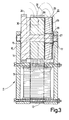
- a self-starting single-phase synchronous motor 11 is shown by itself, as or example can be used to drive a dry shaver.
- a gear 24 is directly formed on the carrier 15 for the cylindrical rotor 14, which forms part of the output of the motor.
- the damping mass 21 is formed in the present embodiment by two adjacent disks 25 and 26.
- the disc 25 is freely rotatable and axially movable on a shaft section 27 of the carrier 15 which runs next to the rotor 14, wherein it is directly adjacent to a side surface 28 of the rotor 14, which is effective here as a stop rotating with the output.
- the second disk 26 is also freely rotatable and axially movable on a cylindrical shoulder 29 which is provided on the side of the disk 25 facing away from the rotor 14, as a result of which the disk 26 is released from the shaft section 27 and thus from the output and thus no frictional losses compared to the Shaft section 27 or the output. In itself, however, it would also be possible to place the disk to on the shaft section 27 itself.
- the first disk 23 is made of non-magnetizable material, whereas the other second disk 26 is made of magnetizable material.
- the first disk 25 predominantly forms the damping mass per se.
- the other second disk 26 is made substantially thinner than the disk 25, at least ten times thinner and serves to deliver the pressing force of the disk 25 to the side surface 28 of the rotor 14.
- the entire damping mass 21 is arranged in the region of the magnetic stray field of the rotor 14, which consists of a diametrically magnetized permanent magnet, the direction of magnetization of which is indicated by the arrow 30.
- the magnetic Stray field of the rotor 14 closes laterally around the rotor, as is indicated in FIG. 3 by the dashed lines 31.
- This magnetic stray field of the permanent-magnet rotor 14 continuously pulls the second disk 26, which is made of magnetizable material, in the direction of the side surface 28 of the rotor, as a result of which the disk 25 in between is constantly pressed against this side surface 28, which forms the stop rotating with the output. In this way, the damping mass 21 can again exert a damping and stabilizing effect on the run of the rotor 14.
- the second disk 26 does not have to be freely rotatable and axially movable by itself, but could also be firmly connected to the disk 25, for example by gluing.
- an eiazige disc consisting of magnetizable material can be used as a damping mass.
- Another possibility would be to insert parts made of magnetizable material into a disc made of non-magnetizable material, which then take care of the pressure of the disc against the stop rotating with the output under the action of the magnetic stray field of the motor.
Landscapes
- Engineering & Computer Science (AREA)
- Power Engineering (AREA)
- Connection Of Motors, Electrical Generators, Mechanical Devices, And The Like (AREA)
- Dynamo-Electric Clutches, Dynamo-Electric Brakes (AREA)
- Vibration Prevention Devices (AREA)
- Dc Machiner (AREA)
- Constituent Portions Of Griding Lathes, Driving, Sensing And Control (AREA)
Applications Claiming Priority (2)
| Application Number | Priority Date | Filing Date | Title |
|---|---|---|---|
| AT0400783A AT378868B (de) | 1983-11-14 | 1983-11-14 | Elektromotor mit einer daempfungseinrichtung |
| AT4007/83 | 1983-11-14 |
Publications (3)
| Publication Number | Publication Date |
|---|---|
| EP0142211A2 true EP0142211A2 (fr) | 1985-05-22 |
| EP0142211A3 EP0142211A3 (en) | 1986-06-04 |
| EP0142211B1 EP0142211B1 (fr) | 1990-08-29 |
Family
ID=3558387
Family Applications (1)
| Application Number | Title | Priority Date | Filing Date |
|---|---|---|---|
| EP84201632A Expired - Lifetime EP0142211B1 (fr) | 1983-11-14 | 1984-11-12 | Moteur électrique avec un dispositif d'amortissement |
Country Status (10)
| Country | Link |
|---|---|
| US (1) | US4827204A (fr) |
| EP (1) | EP0142211B1 (fr) |
| JP (1) | JPS60121939A (fr) |
| KR (1) | KR910003665B1 (fr) |
| AT (1) | AT378868B (fr) |
| CA (1) | CA1231998A (fr) |
| DE (1) | DE3483084D1 (fr) |
| ES (1) | ES8601590A1 (fr) |
| HK (1) | HK12993A (fr) |
| SG (1) | SG112892G (fr) |
Citations (4)
| Publication number | Priority date | Publication date | Assignee | Title |
|---|---|---|---|---|
| US3197659A (en) | 1961-05-02 | 1965-07-27 | Cons Electronics Ind | Motion damper for intermittent rotary devices |
| US3280352A (en) | 1963-07-03 | 1966-10-18 | Garrett Corp | Electric motor having electromagnetic clutch-brake |
| US3790831A (en) | 1972-06-09 | 1974-02-05 | Computer Devices | Apparatus for damping oscillations in a stepping motor |
| DE2362611A1 (de) | 1973-12-17 | 1975-06-19 | Stegmann Uhren Elektro | Anlaufhilfe fuer synchronmotoren mit dauermagnetlaeufer |
Family Cites Families (17)
| Publication number | Priority date | Publication date | Assignee | Title |
|---|---|---|---|---|
| US2114106A (en) * | 1935-08-20 | 1938-04-12 | Geveke William | Grinding device |
| US3379907A (en) * | 1966-03-15 | 1968-04-23 | Endicott Coil Company Inc | Brake mechanism for small induction motors |
| FR1532298A (fr) * | 1967-01-18 | 1968-07-12 | Moteurs Leroy | Moteur-frein perfectionné à manque de courant |
| DE1613141C3 (de) * | 1967-04-21 | 1978-10-19 | Hanning Elektro-Werke Robert Hanning, 4800 Bielefeld | Einphaseninduktionsmotor, bei dem im wesentlichen nur ein einen pulsierenden Magnetfluß erzeugendes Hauptfeld besteht, insbesondere Spaltpolmotor, mit selbsttätig wirkender Bremse |
| US3562565A (en) * | 1968-11-27 | 1971-02-09 | Nippon Denso Co | Dc motor containing a brake means |
| US3579066A (en) * | 1969-04-07 | 1971-05-18 | Tri W G Inc | Brake motor attachment device |
| US3668445A (en) * | 1970-12-21 | 1972-06-06 | Leroy K Grove | Electromagnet for brakes and clutches |
| US3732447A (en) * | 1971-12-13 | 1973-05-08 | F Perhats | Clutch and brake motor arrangement |
| DE2261163C2 (de) * | 1972-12-12 | 1983-06-23 | Rud-Kettenfabrik Rieger & Dietz Gmbh U. Co, 7080 Aalen | Kettengehänge |
| AU504982B2 (en) * | 1975-06-18 | 1979-11-01 | Vdo Adolf Schindling Aktiengesellschaft | Damping device for a stepping motor |
| CH607433A5 (fr) * | 1976-09-21 | 1978-12-15 | Sonceboz Societe Ind De Sa | |
| DE2657658A1 (de) * | 1976-12-20 | 1978-06-22 | Quick Rotan Becker & Notz Kg | Positionierantrieb |
| JPS5442402U (fr) * | 1977-08-30 | 1979-03-22 | ||
| DE3036091C2 (de) * | 1980-09-25 | 1986-01-30 | Hanning Elektro-Werke GmbH & Co, 4811 Oerlinghausen | Elektromotor mit selbsttätig wirkender Bremse |
| JPS5775545A (en) * | 1980-10-24 | 1982-05-12 | Mitsubishi Electric Corp | Rotary electric machine |
| JPS5778347A (en) * | 1980-10-31 | 1982-05-17 | Toshiba Corp | Motor withbrake |
| EP0072774B1 (fr) * | 1981-08-19 | 1985-09-11 | Sodeco-Saia Sa | Moteur synchrone |
-
1983
- 1983-11-14 AT AT0400783A patent/AT378868B/de not_active IP Right Cessation
-
1984
- 1984-11-07 US US06/669,278 patent/US4827204A/en not_active Expired - Fee Related
- 1984-11-08 CA CA000467396A patent/CA1231998A/fr not_active Expired
- 1984-11-12 DE DE8484201632T patent/DE3483084D1/de not_active Expired - Lifetime
- 1984-11-12 EP EP84201632A patent/EP0142211B1/fr not_active Expired - Lifetime
- 1984-11-12 ES ES537570A patent/ES8601590A1/es not_active Expired
- 1984-11-13 KR KR1019840007098A patent/KR910003665B1/ko not_active Expired
- 1984-11-14 JP JP59238686A patent/JPS60121939A/ja active Pending
-
1992
- 1992-11-02 SG SG1128/92A patent/SG112892G/en unknown
-
1993
- 1993-02-18 HK HK129/93A patent/HK12993A/xx not_active IP Right Cessation
Patent Citations (4)
| Publication number | Priority date | Publication date | Assignee | Title |
|---|---|---|---|---|
| US3197659A (en) | 1961-05-02 | 1965-07-27 | Cons Electronics Ind | Motion damper for intermittent rotary devices |
| US3280352A (en) | 1963-07-03 | 1966-10-18 | Garrett Corp | Electric motor having electromagnetic clutch-brake |
| US3790831A (en) | 1972-06-09 | 1974-02-05 | Computer Devices | Apparatus for damping oscillations in a stepping motor |
| DE2362611A1 (de) | 1973-12-17 | 1975-06-19 | Stegmann Uhren Elektro | Anlaufhilfe fuer synchronmotoren mit dauermagnetlaeufer |
Also Published As
| Publication number | Publication date |
|---|---|
| JPS60121939A (ja) | 1985-06-29 |
| ES537570A0 (es) | 1985-10-16 |
| SG112892G (en) | 1993-03-12 |
| KR910003665B1 (ko) | 1991-06-08 |
| CA1231998A (fr) | 1988-01-26 |
| US4827204A (en) | 1989-05-02 |
| ATA400783A (de) | 1985-02-15 |
| ES8601590A1 (es) | 1985-10-16 |
| KR850003636A (ko) | 1985-06-20 |
| EP0142211A3 (en) | 1986-06-04 |
| DE3483084D1 (de) | 1990-10-04 |
| EP0142211B1 (fr) | 1990-08-29 |
| HK12993A (en) | 1993-02-26 |
| AT378868B (de) | 1985-10-10 |
Similar Documents
| Publication | Publication Date | Title |
|---|---|---|
| EP0210557A1 (fr) | Coupleur magnétique avec dispositif magnétique intégré de soulagement de palier | |
| EP0837538A1 (fr) | Générateur à poles à griffes | |
| DE1638302A1 (de) | Elektromotor | |
| EP0116378B1 (fr) | Moteur monophasé synchrone avec magnétisation déplacée angulairement | |
| CH400325A (de) | Elektromotor, insbesondere Kleinspannungs-Gleichstrommotor | |
| DE8435225U1 (de) | Elektromagnetische Kupplung | |
| EP0018574A2 (fr) | Embrayage électro-magnétique sans bagues collectrices | |
| DE1958942A1 (de) | Traegheitsarmer Elektro-Induktionsmotor | |
| DE1927205B2 (de) | Synchronmotor | |
| DE102016124390A1 (de) | Motor vom Innenrotortyp | |
| EP0142211B1 (fr) | Moteur électrique avec un dispositif d'amortissement | |
| DE3143891C1 (de) | Elektromagnetisch betaetigte Federdruckbremse | |
| DE3400065C2 (fr) | ||
| DE102006017233B4 (de) | Rotoranordnung für eine elektrische Maschine und Klauenpolmotor | |
| EP0786852B1 (fr) | Entraínement électrique | |
| DE1184158B (de) | Schleifringlose elektromagnetisch betaetigte Klauen- oder Zahnkupplung | |
| DE2420869C3 (de) | Elektrischer Motor mit einer unidirektionalen Kupplung | |
| DE1763855A1 (de) | Synchronmotor mit eindeutig vorgebbarer Drehrichtung | |
| DE2747644A1 (de) | Einphasenschrittmotor, insbesondere fuer uhren | |
| EP0108434A1 (fr) | Moteur électrique | |
| AT212444B (de) | Geschwindigkeitsregler für elektrische Motoren | |
| EP1661229B1 (fr) | Moteur electrique pourvu d'une bague de reflux | |
| DE1870645U (de) | Schleifringlose elektromagnetkupplung. | |
| AT208662B (fr) | ||
| AT209420B (de) | Selbstanlaufender Synchronmotor, insbesondere Synchron-Kleinmotor |
Legal Events
| Date | Code | Title | Description |
|---|---|---|---|
| PUAI | Public reference made under article 153(3) epc to a published international application that has entered the european phase |
Free format text: ORIGINAL CODE: 0009012 |
|
| AK | Designated contracting states |
Designated state(s): DE FR GB IT NL SE |
|
| PUAL | Search report despatched |
Free format text: ORIGINAL CODE: 0009013 |
|
| AK | Designated contracting states |
Kind code of ref document: A3 Designated state(s): DE FR GB IT NL SE |
|
| 17P | Request for examination filed |
Effective date: 19861124 |
|
| 17Q | First examination report despatched |
Effective date: 19890522 |
|
| GRAA | (expected) grant |
Free format text: ORIGINAL CODE: 0009210 |
|
| AK | Designated contracting states |
Kind code of ref document: B1 Designated state(s): DE FR GB IT NL SE |
|
| PG25 | Lapsed in a contracting state [announced via postgrant information from national office to epo] |
Ref country code: SE Free format text: THE PATENT HAS BEEN ANNULLED BY A DECISION OF A NATIONAL AUTHORITY Effective date: 19900829 Ref country code: NL Effective date: 19900829 |
|
| REF | Corresponds to: |
Ref document number: 3483084 Country of ref document: DE Date of ref document: 19901004 |
|
| GBT | Gb: translation of ep patent filed (gb section 77(6)(a)/1977) | ||
| ITF | It: translation for a ep patent filed | ||
| ET | Fr: translation filed | ||
| NLV1 | Nl: lapsed or annulled due to failure to fulfill the requirements of art. 29p and 29m of the patents act | ||
| PLBI | Opposition filed |
Free format text: ORIGINAL CODE: 0009260 |
|
| 26 | Opposition filed |
Opponent name: VDO ADOLF SCHINDLING AG, FRANKFURT - VERWALTUNGS- Effective date: 19910222 |
|
| ITTA | It: last paid annual fee | ||
| PLBN | Opposition rejected |
Free format text: ORIGINAL CODE: 0009273 |
|
| STAA | Information on the status of an ep patent application or granted ep patent |
Free format text: STATUS: OPPOSITION REJECTED |
|
| 27O | Opposition rejected |
Effective date: 19940719 |
|
| REG | Reference to a national code |
Ref country code: FR Ref legal event code: CD |
|
| PGFP | Annual fee paid to national office [announced via postgrant information from national office to epo] |
Ref country code: GB Payment date: 19961101 Year of fee payment: 13 |
|
| PGFP | Annual fee paid to national office [announced via postgrant information from national office to epo] |
Ref country code: FR Payment date: 19961119 Year of fee payment: 13 |
|
| PGFP | Annual fee paid to national office [announced via postgrant information from national office to epo] |
Ref country code: DE Payment date: 19970127 Year of fee payment: 13 |
|
| PG25 | Lapsed in a contracting state [announced via postgrant information from national office to epo] |
Ref country code: GB Free format text: LAPSE BECAUSE OF NON-PAYMENT OF DUE FEES Effective date: 19971112 |
|
| PG25 | Lapsed in a contracting state [announced via postgrant information from national office to epo] |
Ref country code: FR Free format text: THE PATENT HAS BEEN ANNULLED BY A DECISION OF A NATIONAL AUTHORITY Effective date: 19971130 |
|
| GBPC | Gb: european patent ceased through non-payment of renewal fee |
Effective date: 19971112 |
|
| PG25 | Lapsed in a contracting state [announced via postgrant information from national office to epo] |
Ref country code: DE Free format text: LAPSE BECAUSE OF NON-PAYMENT OF DUE FEES Effective date: 19980801 |
|
| REG | Reference to a national code |
Ref country code: FR Ref legal event code: ST |
|
| APAH | Appeal reference modified |
Free format text: ORIGINAL CODE: EPIDOSCREFNO |