EP0142329A2 - Système de réglage pour un dispositif combinatoire de pesage ou de comptage - Google Patents
Système de réglage pour un dispositif combinatoire de pesage ou de comptage Download PDFInfo
- Publication number
- EP0142329A2 EP0142329A2 EP84307693A EP84307693A EP0142329A2 EP 0142329 A2 EP0142329 A2 EP 0142329A2 EP 84307693 A EP84307693 A EP 84307693A EP 84307693 A EP84307693 A EP 84307693A EP 0142329 A2 EP0142329 A2 EP 0142329A2
- Authority
- EP
- European Patent Office
- Prior art keywords
- central processing
- drive unit
- weighing
- control system
- units
- Prior art date
- Legal status (The legal status is an assumption and is not a legal conclusion. Google has not performed a legal analysis and makes no representation as to the accuracy of the status listed.)
- Granted
Links
Images



Classifications
-
- G—PHYSICS
- G01—MEASURING; TESTING
- G01G—WEIGHING
- G01G19/00—Weighing apparatus or methods adapted for special purposes not provided for in the preceding groups
- G01G19/40—Weighing apparatus or methods adapted for special purposes not provided for in the preceding groups with provisions for indicating, recording, or computing price or other quantities dependent on the weight
- G01G19/42—Weighing apparatus or methods adapted for special purposes not provided for in the preceding groups with provisions for indicating, recording, or computing price or other quantities dependent on the weight for counting by weighing
-
- G—PHYSICS
- G01—MEASURING; TESTING
- G01G—WEIGHING
- G01G19/00—Weighing apparatus or methods adapted for special purposes not provided for in the preceding groups
- G01G19/387—Weighing apparatus or methods adapted for special purposes not provided for in the preceding groups for combinatorial weighing, i.e. selecting a combination of articles whose total weight or number is closest to a desired value
- G01G19/393—Weighing apparatus or methods adapted for special purposes not provided for in the preceding groups for combinatorial weighing, i.e. selecting a combination of articles whose total weight or number is closest to a desired value using two or more weighing units
Definitions
- the present invention relates to a control system for a combinatorial or counting apparatus.
- combinatorial weighing apparatus which operate by supplying articles to be weighed to weighing hoppers associated respectively with weighing machines, effecting a combinatorial operation on weights from the weighing machines with an arithmetic control unit, and opening the weighing hoppers of those weighing machines which give an optimum combination of added weights closest to a target weight as a result of the combinatorial operation, tnus discharging the articles representing the optimum combination of added weights.
- the weighing hoppers having discharged the articles are immediately supplied with articles for a next weighing cycle from pool hoppers disposed above the weighing hoppers.
- the pool hoppers are supplied with distributed articles from a storage unit by means of an electromagnetic feeder.
- Fig. 1 of the accompanying drawings shows in block form such combinatorial weighing apparatus. Designated at 1 are a plurality of weighing machines Wl through Wn which issue weight values Xl through Xn (analog signals) to a multiplexer 2.
- an arithmetic control unit 4 comprising a computer applies a signal X to the multiplexer 2 in response to a timing signal T from a packaging machine 5, the weight signals applied to the multiplexer 2 are successively fed to an A/D converter 3.
- the weight signals are converted by the A/D converter 3 into digital signals which are applied to the arithmetic control unit 4.
- the arithmetic control unit 4 stores the digital signals in a memory 6, reads a necessary command from the memory 6, effect combinatorial additions to find combinations of total weight values, compares the weight combinations with a target weight value Xs, and determine a combination of total weights whichi is closest to the target weight value Xs.
- the arithmetic control unit 4 applies a control sin g al C to a weight machine driver 7 such as for the weighing hoppers or a discharge device, and then applies control signals to the electromagnetic feeder, the pool hoppers, and the weight hoppers.
- control system is composed of a central processing unit (CPU)
- CPU central processing unit
- the CPU runs out of control due to a noise signal
- the CPU is required to be reset by itself.
- a microcomputer generally starts its operation by reading a command from a ROM (read-only memory) into a CPU, as illustrated in Fig. 2 of the accompanying drawings.
- the ROM automatically delivers an instruction word to a data bus. Since the combinatorial weighing apparatus has an electromagnetic feeder actuated by SCRs (thyristors) which are phase-controlled, an electric noise signal tends to be applied to the CPU for thereby reading a wrong instruction word. For example, where there are instruction words 1 tnrough 4 composed of 3 bytes, 2 bytes, 2 bytes, and 3 bytes, respectively, as shown in Fig. 3(a), the instruction word 2 may be read as a 3-byte instruction word, as shown in Fig . 3 (b) , or an addressing command such as a CALL command or a JUMP command may be read in error, wnereupon the microcomputer system will not operate properly.
- SCRs thyristors
- a useful improvement would lie in providing a control system for combinatorial weighing or counting apparatus, in wnich a program for controlling the control system including a microcomputer is composed of interrupt routines so that each of a plurality of processes can be started with a proper address without any erroneous operation initiated by a noise signal after each process has been completed.
- Another useful improvement would lie in providing a control system for combinatorial weighing or counting apparatus, which includes a microcomputer system that can be reset by itself properly for each drive unit by resetting a correct interrup wait address when an interrupt routine is started to thereby restore a microcomputer, even if erroneous operation has been effected before the interrup routine is started.
- An embodiment of the present invention can provide a control system for a combinatorial weighing or counting apparatus for weighing articles charged in a plurality of weighing machines, effecting a combinatorial arithmetic operation on obtained weights or numbers of the articles converted from the weights, selecting an optimum combination of added weights or numbers which are closest to a target combination, and aischarging the articles from those weighing machines which give the selected combination, the control system comprising a main central processing unit for effecting the combinatorial arithmetic operation, and a plurality of individual drive unit central processing units associated respectively with driver units of the weighing machines and connected to the main central processing unit for controlling the drive units, respectively, the arrangement being such that operation commands delivered from the main central processing unit to the individual drive unit central processing units are set by interrupt processes of the individual drive unit central processing units at all times.
- Command signals from the main central processing unit to the individual drive unit central processing units are preferably delivered through a data bus line connected to the main central processing unit.
- the command signals from the main central processing unit to the individual drive unit central processing units are preferably generated in synchronism with zero crossing points of an AC power supply for each of the drive units.
- the individual drive unit central processing units are preferably interconnected by a data highway connected to the main central processing unit by a data bus line.
- a microcomputer starts executing an inter- ru pt program when interrupted by an electric signal from an external source. Since an interrupt process has highest priority, and a start address of the interrupt program is prescribed, the interrupt process will not be started in error by noise.
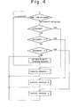
- FIG. 4 is illustrative of a flowchart of a control procedure.
- a CPU accepts the request and executes a process 1 according to a prescribed program.
- the CPU returns to an address of an interrupt wait program for waiting for an interrupt command.
- the CPU executes processes 2, 3 in response to interrupt requests 2, 3, respectively, and thereafter returns to the address of the interrupt wait program.
- Such an interrupt procedure will be compared with a conventional interrupt procedure shown in Fig. 5.
- interrupt requests 1 through 5 are successively accepted by a CPU which jumps to a certain address to execute a program.
- independent interrupt wait addresses are established respectively for interrupt requests 1 through 5 (Fig.6).
- a processing program to be executed by a microcomputer is all composed of interrupt programs, and a necessary procedure is started in response to an electric signal applied to an interrupt input terminal at all times.
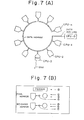
- a combinatorial weighing apparatus to which the embodiment can be applied has a plurality of independent drive units, and central processing units CPU-1 through CPU-n are associated respectively with the drive units and connected to a main CPU-0 for high-level processing operation.
- Fig. 7(A) schematically shows such a computer control system in which the drive unit CPUs CPU1 through CPU-n are interconnected by a data highway coupled by a data bus line to the main CPU CPU-0.
- Each of the drive units is constructed as shown in Fig. 7(B).
- Each drive unit is composed of a feeder time/ feeder strength control device 1, a pool hopper clutch 2, a pool hopper brake 3, a pool hopper operation sensor 4, a weighing hopper clutch 5, a weighing hopper brake 6, and a weighing hopper operation sensor 7.
- a feeder is controlled by the feeder time/feeder strength control device 1.
- a pool hopper is operated with the pool hopper clutch 2 and the pool hopper brake 3.
- the pool hopper operation sensor 4 ascertains whether the pool hopper has operated properly or not.
- a weighing hopper is operated with the weighing hopper clutch 5 and the weighing hopper brake 6.
- the weighing hopper operation sensor 7 ascertains whether the weighing hopper has operated properly or not.
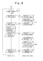
- Fig. 8 is a flowchart of processes of operation of the main CPU CPU-0 and the driver unit CPUs CPU-1 through CPU-n and their interrelationship.
- the main CPU delivers a weight data request signal to each of the driver unit CPUs.
- the driver unit CPUs read weight data from the weighing machines into the A/D converters and deliver the weight data to the main CPU ⁇ step (1) ⁇ .
- the main CPU stores the weight data, effects a combinatorial operation on the weight data, selects those weighing hoppers which give an optimum weight combination, and issues drive request signals to drive unit CPUs for driving the weighing machines.
- the drive unit CPUs having received the request signals drive the weighing hoppers, the pool hoppers, and preset the feeder, and, upon completion of such control, deliver a completion command to the main CPU ⁇ processing step (2)).
- Fig. 9 shows a flowchart of specific details of the interrupt process of the drive unit CPU in each drive unit.
- the interrupt process is started by the request signal from the data bus line or a signal generated at a zero crossing point when an AC 200 V changes from a negative voltage to a positive voltage.
- the zero crossing point is detected from an AC power supply which drives the electromagnetic feeder. Therefore, where a power supply of 60 Hz is employed, 60 interrupt signals per second are generated.
- the interrupt signal is applied during a HALT routine of the CPU. Under abnormal condition, however, the interrupt signal is applied while the CPU is running out of control.
- the drive unit CPU checks a stack register address to ascertain if the HALD condition of the CPU has been executed at normal addresses for thereby confirming if the CPU has run out of control or not. If the CPU has run out of control, then the address is rewritten as a proper address, i.e., an address in the HALT routine, and input/output ports are initialized.
- the drive unit CPU checks what has caused the interrupt process. If the interrupt process is started by a data bus line request from the main CPU, then the step (1) or (2) is executed. After the step (1) or (2) has been over, the drive unit CPU returns to the HALT routine. If the interrupt process is started by 200-V zero crossing, then the drive unit CPU first ascertains if the count of a feeder drive counter is zero or not. If zero, then the drive unit CPU returns to the HALT routine.
- the feeder drive counter is set to a preset value in a feeder presetting step in the step (2) in Fig. 8, after a hopper drive command has been received.
- a firing angle timer for the SCR for driving the electromagnetic'feeder is actuated to ignite the SCR at a phase angle t as shown in Fig. 10, and then the drive unit CPU returns to the HALT routine.
- the feeder operates during a prescribed time, or periods set by the drive counter. If the operation time is 0.3 second, then the feeder is driven in 18 periods in the case of a 60 Hz power supply. The operation continues until the count of the drive counter falls to zero. When the count of the drive counter becomes zero, the SCR is extinguished and the drive unit CPU returns to the HALT routine, as illustrated in Fig. 9.
Landscapes
- Physics & Mathematics (AREA)
- General Physics & Mathematics (AREA)
- Engineering & Computer Science (AREA)
- Mathematical Physics (AREA)
- Theoretical Computer Science (AREA)
- Weight Measurement For Supplying Or Discharging Of Specified Amounts Of Material (AREA)
- Control By Computers (AREA)
Applications Claiming Priority (2)
| Application Number | Priority Date | Filing Date | Title |
|---|---|---|---|
| JP58209623A JPH0663815B2 (ja) | 1983-11-08 | 1983-11-08 | 組合せ計量又は計数装置 |
| JP209623/83 | 1983-11-08 |
Publications (3)
| Publication Number | Publication Date |
|---|---|
| EP0142329A2 true EP0142329A2 (fr) | 1985-05-22 |
| EP0142329A3 EP0142329A3 (en) | 1986-04-02 |
| EP0142329B1 EP0142329B1 (fr) | 1989-10-04 |
Family
ID=16575857
Family Applications (1)
| Application Number | Title | Priority Date | Filing Date |
|---|---|---|---|
| EP84307693A Expired EP0142329B1 (fr) | 1983-11-08 | 1984-11-07 | Système de réglage pour un dispositif combinatoire de pesage ou de comptage |
Country Status (5)
| Country | Link |
|---|---|
| US (2) | US4658919A (fr) |
| EP (1) | EP0142329B1 (fr) |
| JP (1) | JPH0663815B2 (fr) |
| AU (1) | AU564805B2 (fr) |
| DE (1) | DE3480024D1 (fr) |
Cited By (2)
| Publication number | Priority date | Publication date | Assignee | Title |
|---|---|---|---|---|
| EP0267663A3 (fr) * | 1986-11-14 | 1989-02-22 | Ishida Scales Mfg. Co. Ltd. | Système de pesage |
| EP0267664A3 (fr) * | 1986-11-14 | 1989-03-15 | Ishida Scales Mfg. Co. Ltd. | Système de réglage par ordinateur |
Families Citing this family (22)
| Publication number | Priority date | Publication date | Assignee | Title |
|---|---|---|---|---|
| JPS62299724A (ja) * | 1986-06-20 | 1987-12-26 | Ishida Scales Mfg Co Ltd | 計量装置 |
| JPS6321517A (ja) * | 1986-07-14 | 1988-01-29 | Yamato Scale Co Ltd | 組合せ秤用物品供給制御装置 |
| JPS63127119A (ja) * | 1986-11-15 | 1988-05-31 | Ishida Scales Mfg Co Ltd | 計量装置 |
| JPS63127120A (ja) * | 1986-11-15 | 1988-05-31 | Ishida Scales Mfg Co Ltd | 計量装置 |
| US4905779A (en) * | 1987-06-01 | 1990-03-06 | Yamato Scale Company, Limited | Operation condition collator and methods |
| JPS6412232A (en) * | 1987-07-03 | 1989-01-17 | Yamato Scale Co Ltd | Number combination scale |
| JPH02161961A (ja) * | 1988-12-15 | 1990-06-21 | Nippon Kenko Zoushin Kenkyukai:Kk | 時間表示装置 |
| US4909338A (en) * | 1989-06-12 | 1990-03-20 | Ncr Corporation | Method and apparatus for scale calibration and weighing |
| JP2516128B2 (ja) * | 1991-12-28 | 1996-07-10 | 株式会社イシダ | 組合せ計量又は計数装置 |
| US5270495A (en) * | 1992-02-28 | 1993-12-14 | Package Machinery Company | Combination weighing machine with feed control |
| US20040176874A1 (en) * | 1994-09-15 | 2004-09-09 | Scanvaegt A/S | Method and apparatus for weight controlled portioning of articles having non-uniform weight |
| JP3681248B2 (ja) * | 1996-08-23 | 2005-08-10 | 大和製衡株式会社 | 計量システム |
| JP3681249B2 (ja) * | 1996-08-23 | 2005-08-10 | 大和製衡株式会社 | 計量及び包装システム |
| DE19811837C1 (de) * | 1998-03-18 | 1999-10-14 | Multipond Waegetechnik Gmbh | Kombinationswaage |
| US6566613B1 (en) * | 2000-11-03 | 2003-05-20 | Enzo Gesuita | Control system for multihead weigher |
| US6576849B2 (en) * | 2000-12-01 | 2003-06-10 | Mettler-Toledo, Inc. | Load cell diagnostics and failure prediction weighing apparatus and process |
| US8374887B1 (en) | 2005-02-11 | 2013-02-12 | Emily H. Alexander | System and method for remotely supervising and verifying pharmacy functions |
| CN101581597A (zh) * | 2009-06-29 | 2009-11-18 | 广东海川智能机器有限公司 | 一种组合称重装置及其操作方法 |
| WO2012098592A1 (fr) * | 2011-01-20 | 2012-07-26 | 大和製衡株式会社 | Dispositif de pesage |
| CN102424122B (zh) * | 2011-08-12 | 2013-08-21 | 广东海川智能机器有限公司 | 组合秤的控制方法 |
| SG10202109116YA (en) | 2014-09-08 | 2021-09-29 | Becton Dickinson Co | System and method for preparing a pharmaceutical compound |
| CN108692801B (zh) * | 2017-04-12 | 2022-01-28 | 梅特勒-托利多(常州)精密仪器有限公司 | 称重测量系统及计量系统 |
Family Cites Families (13)
| Publication number | Priority date | Publication date | Assignee | Title |
|---|---|---|---|---|
| US4251874A (en) * | 1978-10-16 | 1981-02-17 | Pitney Bowes Inc. | Electronic postal meter system |
| US4165633A (en) * | 1978-02-09 | 1979-08-28 | Motorola Process Control Inc. | System for measuring moisture content |
| DE7812666U1 (de) * | 1978-04-26 | 1978-09-21 | Ledermann Gmbh + Co, 7240 Horb | Bohrwerkzeug |
| DD142135A3 (de) * | 1978-05-03 | 1980-06-11 | Wolfgang Henzler | Mehrrechnerkopplung |
| FR2425713A1 (fr) * | 1978-05-09 | 1979-12-07 | Antivols Simplex Sa | Interrupteur electrique rotatif pour vehicules automobiles |
| US4271470A (en) * | 1979-02-21 | 1981-06-02 | Pitney Bowes Inc. | Serial data bus for use in a multiprocessor parcel postage metering system |
| JPS5714723A (en) * | 1980-06-21 | 1982-01-26 | Pitney Bowes Inc | Multiplex processor parcel postage measuring system with series data bus containing data inspector |
| JPS5737217A (en) * | 1980-08-15 | 1982-03-01 | Ishida Scales Mfg Co Ltd | Counting method |
| JPS5739319A (en) * | 1980-08-20 | 1982-03-04 | Ishida Scales Mfg Co Ltd | Display method for result of combinational operation |
| US4410962A (en) * | 1981-02-17 | 1983-10-18 | Pitney Bowes Inc. | Mailing system interface interconnecting incompatible communication systems |
| US4418771A (en) * | 1982-02-01 | 1983-12-06 | The Woodman Company | Method and apparatus for combination weighing |
| US4550792A (en) * | 1982-09-30 | 1985-11-05 | Eagle Machinery Company | Combination weighing system |
| US4565253A (en) * | 1984-02-03 | 1986-01-21 | Penta-Pak Inc. | Computerized combination weigher with preset optimum weigher discharge |
-
1983
- 1983-11-08 JP JP58209623A patent/JPH0663815B2/ja not_active Expired - Lifetime
-
1984
- 1984-11-07 DE DE8484307693T patent/DE3480024D1/de not_active Expired
- 1984-11-07 US US06/668,894 patent/US4658919A/en not_active Expired - Fee Related
- 1984-11-07 AU AU35170/84A patent/AU564805B2/en not_active Ceased
- 1984-11-07 EP EP84307693A patent/EP0142329B1/fr not_active Expired
-
1986
- 1986-07-08 US US06/883,389 patent/US4733363A/en not_active Expired - Fee Related
Cited By (2)
| Publication number | Priority date | Publication date | Assignee | Title |
|---|---|---|---|---|
| EP0267663A3 (fr) * | 1986-11-14 | 1989-02-22 | Ishida Scales Mfg. Co. Ltd. | Système de pesage |
| EP0267664A3 (fr) * | 1986-11-14 | 1989-03-15 | Ishida Scales Mfg. Co. Ltd. | Système de réglage par ordinateur |
Also Published As
| Publication number | Publication date |
|---|---|
| EP0142329B1 (fr) | 1989-10-04 |
| AU564805B2 (en) | 1987-08-27 |
| JPS60100724A (ja) | 1985-06-04 |
| JPH0663815B2 (ja) | 1994-08-22 |
| EP0142329A3 (en) | 1986-04-02 |
| DE3480024D1 (en) | 1989-11-09 |
| US4733363A (en) | 1988-03-22 |
| US4658919A (en) | 1987-04-21 |
| AU3517084A (en) | 1985-05-16 |
Similar Documents
| Publication | Publication Date | Title |
|---|---|---|
| US4658919A (en) | Control system for combinatorial weighing or counting apparatus | |
| US4534428A (en) | Vibratory feeder control for a weighing system | |
| US4268906A (en) | Data processor input/output controller | |
| EP0464615A2 (fr) | Micro-ordinateur équipé d'un appareil de commande DMA | |
| US5163152A (en) | Interrupt control apparatus for a microprocessor providing real time priority processing of interrupt requests | |
| US4393446A (en) | Routine timer for computer systems | |
| US4396078A (en) | Weighing or counting method with some unfilled hoppers | |
| EP0140424B1 (fr) | Dispositif pour régler la vitesse du moteur | |
| US5968159A (en) | Interrupt system with fast response time | |
| US4642788A (en) | Combinatorial weighing method and apparatus | |
| US5297290A (en) | Method and apparatus for interruption processing in multi-processor system | |
| US6184904B1 (en) | Central processing unit for a process control system | |
| EP0026083A1 (fr) | Système de traitement de données à plusieurs processeurs | |
| US4618013A (en) | Combination weighing machine with auxiliary weight hopper | |
| JP2516128B2 (ja) | 組合せ計量又は計数装置 | |
| KR930006516B1 (ko) | 데이타 처리시스템 | |
| Susor | Computers in the Glass Batching Industry | |
| JP3981918B2 (ja) | 高炉設備の秤量演算処理方法 | |
| GB2030331A (en) | Real-time Data Processing System for Processing Time Period Commands | |
| JPS6238851A (ja) | エンジン制御装置 | |
| EP0306619B1 (fr) | Méthode de mesurage combinatoire et dispositif | |
| JPH0666062B2 (ja) | シーケンス制御装置 | |
| US5497481A (en) | Microcomputer computer system having plural programmable timers and preventing memory access operations from interfering with timer start requests | |
| JPH0814779B2 (ja) | 演算制御装置の初期化方法 | |
| JPS61156307A (ja) | シ−ケンス制御装置 |
Legal Events
| Date | Code | Title | Description |
|---|---|---|---|
| PUAI | Public reference made under article 153(3) epc to a published international application that has entered the european phase |
Free format text: ORIGINAL CODE: 0009012 |
|
| AK | Designated contracting states |
Designated state(s): DE FR GB IT |
|
| PUAL | Search report despatched |
Free format text: ORIGINAL CODE: 0009013 |
|
| AK | Designated contracting states |
Kind code of ref document: A3 Designated state(s): DE FR GB IT |
|
| 17P | Request for examination filed |
Effective date: 19860818 |
|
| 17Q | First examination report despatched |
Effective date: 19871013 |
|
| GRAA | (expected) grant |
Free format text: ORIGINAL CODE: 0009210 |
|
| AK | Designated contracting states |
Kind code of ref document: B1 Designated state(s): DE FR GB IT |
|
| ET | Fr: translation filed | ||
| REF | Corresponds to: |
Ref document number: 3480024 Country of ref document: DE Date of ref document: 19891109 |
|
| ITF | It: translation for a ep patent filed | ||
| PLBE | No opposition filed within time limit |
Free format text: ORIGINAL CODE: 0009261 |
|
| STAA | Information on the status of an ep patent application or granted ep patent |
Free format text: STATUS: NO OPPOSITION FILED WITHIN TIME LIMIT |
|
| 26N | No opposition filed | ||
| ITTA | It: last paid annual fee | ||
| REG | Reference to a national code |
Ref country code: GB Ref legal event code: IF02 |
|
| PGFP | Annual fee paid to national office [announced via postgrant information from national office to epo] |
Ref country code: GB Payment date: 20031105 Year of fee payment: 20 |
|
| PGFP | Annual fee paid to national office [announced via postgrant information from national office to epo] |
Ref country code: FR Payment date: 20031110 Year of fee payment: 20 |
|
| PGFP | Annual fee paid to national office [announced via postgrant information from national office to epo] |
Ref country code: DE Payment date: 20031120 Year of fee payment: 20 |
|
| PG25 | Lapsed in a contracting state [announced via postgrant information from national office to epo] |
Ref country code: GB Free format text: LAPSE BECAUSE OF EXPIRATION OF PROTECTION Effective date: 20041106 |
|
| REG | Reference to a national code |
Ref country code: GB Ref legal event code: PE20 |