EP0142441A2 - Pendelverkehr-Kabelbahn - Google Patents
Pendelverkehr-Kabelbahn Download PDFInfo
- Publication number
- EP0142441A2 EP0142441A2 EP84402268A EP84402268A EP0142441A2 EP 0142441 A2 EP0142441 A2 EP 0142441A2 EP 84402268 A EP84402268 A EP 84402268A EP 84402268 A EP84402268 A EP 84402268A EP 0142441 A2 EP0142441 A2 EP 0142441A2
- Authority
- EP
- European Patent Office
- Prior art keywords
- cabin
- cable car
- car system
- doors
- hanger
- Prior art date
- Legal status (The legal status is an assumption and is not a legal conclusion. Google has not performed a legal analysis and makes no representation as to the accuracy of the status listed.)
- Granted
Links
Images

Classifications
-
- B—PERFORMING OPERATIONS; TRANSPORTING
- B61—RAILWAYS
- B61B—RAILWAY SYSTEMS; EQUIPMENT THEREFOR NOT OTHERWISE PROVIDED FOR
- B61B7/00—Rope railway systems with suspended flexible tracks
- B61B7/04—Rope railway systems with suspended flexible tracks with suspended tracks serving as haulage cables
-
- B—PERFORMING OPERATIONS; TRANSPORTING
- B61—RAILWAYS
- B61B—RAILWAY SYSTEMS; EQUIPMENT THEREFOR NOT OTHERWISE PROVIDED FOR
- B61B12/00—Component parts, details or accessories not provided for in groups B61B7/00 - B61B11/00
Definitions
- the invention relates to a reciprocating cable car system making it possible to improve the flow of passengers and the general operating conditions, which will result in appreciable operating savings. More specifically, it is aimed at a reciprocating cable car system having both improvements in the transport cabin and the embarkation and disembarkation docks.
- the cabins are subjected to relatively frequent and sometimes severe shocks against the guides of the pylons and the platforms of the stations, these shocks most often occurring on the side faces of the cabin.
- the presence of side doors which are designed as wide as possible, does not allow the establishment of a lateral protection device which could, on the one hand, absorb impacts and, on the other hand, distribute them on several elements of the cabin structure.
- These shocks result in frequent deformations of the vertical uprights of the cabin frame, the reinforcement of which is limited for weight considerations.
- Others summer Improvements due to these shocks or impacts can also occur at the angles of the cabin roof according to the line profiles.
- the cable car system according to the invention allows cabins to be filled and evacuated by their upstream and downstream ends, thus largely eliminating the drawbacks of cabins of the prior art.
- the retractable doors releasing the upstream and downstream panels of the cabin over the entire length and its height are constituted by rolling shutters circulating in the longitudinal direction of the cabin, along structures appropriate guides, for example, slides from the floor until the door is completely erased under the cabin roof.
- the roller shutters will advantageously consist of elements, either hinged together, is independent of each other, but in any case arranged so as to ensure a sufficient seal and a distribution over several of them of the possible thrust of the travelers unbalanced by a longitudinal swing of relatively large amplitude.
- each element will be provided with rollers, for example in Teflon or in any other material which is both light and resistant; the guides in light alloys or in composite material, must be shaped and fixed to the main structure so that the movement of the doors is easy and rapid in all circumstances, that is to say is not practically likely to be affected by guide deformations.
- the operation of the doors will be either manual or automatically controlled, for example by an electrical system, while providing a manual emergency device.
- the cab control station will be located in the middle of the side panel located on the side of the center line of the track.
- a door In the immediate vicinity of the control station, a door will be provided allowing the operating and maintenance staff lateral access to the platforms as well as to the pylon gateways supporting the line. This door will also usable for filling or evacuating the cabin under certain operating conditions.
- This side door may be designed in the same way as the upstream and downstream doors, with however a displacement perpendicular to the axis of the track, or else will be constituted by a rigid panel sliding along this side wall of the cabin.
- the constraint of the large clearance on the two lateral walls of the cabin leads to treating the hanger and the cabin as two independent structures linked together by four points on which all the constraints are concentrated.
- this constraint has dissipated and it is now possible to design a completely new suspension-cabin assembly, constituted by a frame carrying a body which, protected from shocks and impacts and non-bearing, can be very lightened , while the main stresses can be distributed over the entire frame.
- the hanger will be made either with profiles or with tubes, in materials capable of withstanding usage constraints, for example light alloy, fiberglass and / or aramid, as well as any composite material having the required properties. resistance to mechanical stresses as well as to physical factors and weather conditions to which these installations may be exposed.
- the components of the hanger can be assembled by any suitable technique, for example by riveting, welding, bolting, keying, gluing and the like. If possible, a design and mounting technique will be adopted allowing for on-site assemblies and facilitating the replacement or repair of damaged or tired elements.
- the external suspension arm fixed to the trolley will descend to the level of the cabin floor which will be formed by longitudinal structural elements integral with the suspension arm and between the which we will have the panels. From the interior side, uprights will be provided which are integral with the longitudinal elements and, where appropriate, integral with the hanger arm above the cabin, these elements serving to bond the cabin and to fix anti-shock devices for the parts. the most exposed of the latter.
- the floor will be calculated so as to support, among other things, the things due to the possible longitudinal swinging of the loads at the time of contact with the arrival platform.
- the guides of the upstream and downstream doors of the cabin will be fixed to the elements of this hanger so as to ensure their rigidity. It is also conceivable that the elements of the hanger are shaped so as to present a suitable guiding solution for the retraction of the doors.
- the cabin bodywork can therefore be produced by light panels fixed to the elements of the hanger on the site itself, thus avoiding all the disadvantages of transporting complete cabins from the workshops and facilitating any repairs.
- the devices for absorbing and absorbing shocks or side impacts will be constituted by light elements made of material resistant to shocks or impacts and facilitating sliding along the guides. It is clear that the shapes and locations of these protective elements will depend on the characteristics of the installation.
- the docking system A reciprocating cable car according to the present invention is provided with two specific devices, namely means for constant leveling of the cabin and damping and bridge means.
- the constant leveling means consist of shoes intended to support the carrier cable (s) as well as the tractor cable (s), so that in the docking position, the level of the cabin floor is constant whatever whatever the load. It is indeed essential that the contact between the end of the cabin and the quay be made in a precise and well-limited area, in height to correspond to the structure of the floor. In particular, even with longitudinal oscillations of moderate amplitude, the cabin must not be able to pass over the platform or strike it above the level of the floor. These shoes will advantageously have a length corresponding to that of the cabin.
- the cabin is likely to oscillate in the longitudinal direction around the suspension axis under the effect of braking and / or tensioning of the tractor cable. Furthermore, it is necessary that the interval to be crossed by travelers between the cabin and the platform is as short as possible for obvious safety reasons. This is why, according to the present invention, damping means have been provided. sisters and walkways consisting of at least one damping device and arranged between the quay proper and the cabin.
- the damping device comprises a fixed part enclosing the damping means and a movable rod secured to a stop element, this rod bearing on these damping means and supporting a movable floor or gangway intended to be in contact with the floor of the cabin as soon as it stops in order to avoid any loss of time on the cycle.
- This mobile gangway is parallel to the gangway or fixed floor of the arrival platform, and is located at the level of the cabin, when the latter, in the docking position, comes into contact with the stopper element capable of absorbing and to quickly dampen the oscillations after the carriage stops, and against which the cabin will be held in abutment in the stabilized position in the station.
- an interval will be left to remain which will be determined in agreement with the control authorities.
- the waiting area will be extended over half of this interval by a sheet metal or metal grating floor supported on the structures of the masonry docks or in metal frame; the other half of the interval will be occupied by a movable floor of the same type which can slide under the fixed floor, this movable floor being supported by a chassis moving on slides integral with the platform structures.
- This chassis will have a vertical wall on the cabin side, the external face of which is provided with an elastic hollow body will be in contact with the cabin floor in the final phase of entry into the station, and the internal face will be in contact with a device.
- the adjustments of the movable chassis and of the stop position of the carriage will be determined so that in the stabilized position when stopped, the cabin is in contact with the external face of the movable chassis without appreciable compression of the elastic device. .
- the cycle of a trip is reduced to an appreciable extent, which results in an increase in speed, the improvement of which is all the more more sensitive than the actual journey time is short, and on the other hand, it improves the possibility of exploitation by side wind.
- the invention will make it possible to reduce the weight as well as the cost price of the hanger and the passenger compartment while offering better protection as well as ease of maintenance, control and repair. It is clear that savings on the weight of the line and the passenger compartment will have a significant economic impact.
- a cabin A is shown in the docking position in an area B 1 of a platform B.
- a damper and bridge device C In the other area B 2 of docking of the platform B is schematically represented a damper and bridge device C.
- the cabin A is stabilized by means of the guide device D, extending over approximately the entire length of the cabin and supported by a gantry E.
- Cabin A is advantageously constituted by a hanger and a passenger compartment housed in said hanger.
- the hanger is constituted by a frame comprising a trapezoidal zone 1 secured by its small base to the support arm 2 comprising an axis 2a fixed to the carriage (not shown in the drawings), while at the right of the large base of the frame extends a rectangular area 3.
- This area 3 consists of two longitudinal sections 3a and 3b transverse to the right of which are secured amounts 4 defining with longitudinal crosspieces 5a and 5b transverse the external configuration of the cabin.
- the corner uprights 4a and the longitudinal crosspieces 5a are advantageously in profiles internally shaped in slides for receiving flaps 6 intended for closing the doors of the upstream and downstream sides of the cabin. These components are formed by blades 6a articulated or not, some of which are transparent.
- At the side faces of the cabin is also provided at least one door, not shown in the drawings and intended for the entry and exit of the personnel operating and maintaining the installation, as well as possibly passengers, thereby doing emergency door office, and access to pylon walkways.
- This side door is advantageously arranged on the side face opposite the trapezoidal structure of the hanger, that is to say the side docking face.
- a roller system is provided to, in cooperation with the uprights and the corresponding bushings, allow the swinging of the upstream doors and downstream of the cabin.
- the guiding devices along the central platform and the protection of the cabins are not shown.
- the means for leveling the cabin at the station consist of a shoe D of conventional type carried by a bracket E.
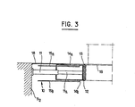
- the bridge damping means C are constituted by a damping device 10 fixed to the platform B 2 and having a body 11 enclosing the damping means proper, for example a hydraulic fluid, a spring, Belleville washers and the like.
- the rod 11a of the damping device being substantially in line with the vertical wall of the platform, at the level of the waiting zone and has at its free end a stop element, for example a stop 12 covered with a pad of elastic material 13
- the stopper 12 extends parallel to the fixed floor 18 extending the waiting areas of the platform and slightly below the fixed floor, a movable floor 14 resting on its upper 14a and lower 14b faces on slides 15a, 15b respectively.
- the cabin In operation of the cable car system according to the invention, the cabin, when it comes into the docking position, engages by its towing cables 9 in the guide shoe D before coming into contact with the load-bearing damping device of the gangway or movable floor 14 which is located at the floor (19) of the cabin.
- the driver After stabilization of the latter, the driver only has to open, by automatic and / or pneumatic means, the front door of the cabin and the passengers can be quickly evacuated from the latter so that the subsequent filling of the passengers by waiting can be done in the best conditions before resuming the usual journey cycle of the cabin.
- the cable system of the invention provides the solution to the problem of the fluidity of passenger entry and exit, thanks to the front and rear position of the main cabin access doors.
- this design completely changes the conventional distribution of stresses between hanger and cabin which was, until now, particularly unfavorable.
Landscapes
- Engineering & Computer Science (AREA)
- Transportation (AREA)
- Mechanical Engineering (AREA)
- Body Structure For Vehicles (AREA)
- Insulated Conductors (AREA)
- Measurement And Recording Of Electrical Phenomena And Electrical Characteristics Of The Living Body (AREA)
- Medicines Containing Antibodies Or Antigens For Use As Internal Diagnostic Agents (AREA)
- Microscoopes, Condenser (AREA)
- Communication Cables (AREA)
Priority Applications (1)
| Application Number | Priority Date | Filing Date | Title |
|---|---|---|---|
| AT84402268T ATE29989T1 (de) | 1983-11-10 | 1984-11-09 | Pendelverkehr-kabelbahn. |
Applications Claiming Priority (2)
| Application Number | Priority Date | Filing Date | Title |
|---|---|---|---|
| FR8317957A FR2554774B1 (fr) | 1983-11-10 | 1983-11-10 | Systeme de telepherique a va-et-vient |
| FR8317957 | 1983-11-10 |
Publications (3)
| Publication Number | Publication Date |
|---|---|
| EP0142441A2 true EP0142441A2 (de) | 1985-05-22 |
| EP0142441A3 EP0142441A3 (en) | 1985-06-19 |
| EP0142441B1 EP0142441B1 (de) | 1987-09-30 |
Family
ID=9294015
Family Applications (1)
| Application Number | Title | Priority Date | Filing Date |
|---|---|---|---|
| EP84402268A Expired EP0142441B1 (de) | 1983-11-10 | 1984-11-09 | Pendelverkehr-Kabelbahn |
Country Status (3)
| Country | Link |
|---|---|
| EP (1) | EP0142441B1 (de) |
| AT (1) | ATE29989T1 (de) |
| FR (1) | FR2554774B1 (de) |
Cited By (3)
| Publication number | Priority date | Publication date | Assignee | Title |
|---|---|---|---|---|
| EP1034996A1 (de) * | 1999-03-10 | 2000-09-13 | Hölzl Construzioni Funivie S.r.l. | Abfahrts- und Ankunftstation für eine Zweiseilbahn wie auch Kabine zur Beförderung von in einer solchen Station aufzuladenden und abzuladenden Fahrgästen |
| RU2481213C2 (ru) * | 2008-12-08 | 2013-05-10 | Иннова Патент Гмбх | Устройство для перевозок по канатной дороге, оборудованное средствами амортизации |
| CN113459518A (zh) * | 2021-08-04 | 2021-10-01 | 江阴奇南机械有限公司 | 一种轻便型高强度缆车轿厢 |
Family Cites Families (7)
| Publication number | Priority date | Publication date | Assignee | Title |
|---|---|---|---|---|
| CH174505A (de) * | 1933-12-22 | 1935-01-15 | Constam Ernst | Seilschwebebahn mit bei einer Stütze angeordneter Haltestelle. |
| US2248960A (en) * | 1939-10-07 | 1941-07-15 | Collis Lloyd | Unloading and loading system |
| CH217921A (de) * | 1940-10-16 | 1941-11-15 | Von Roll Ag | Verfahren zum Transportieren von Gütern mittels Kabinen von Seilschwebebahnen und Seilschwebebahn hierzu. |
| FR2238626B1 (de) * | 1973-07-26 | 1976-04-30 | Aerotrain | |
| JPS5842060B2 (ja) * | 1979-02-05 | 1983-09-16 | 日産自動車株式会社 | 懸垂車両のロ−リング静定装置 |
| FR2453060A1 (fr) * | 1979-04-04 | 1980-10-31 | Mashkovsky Arkady | Transporteur aerien |
| FR2496029A1 (fr) * | 1980-12-15 | 1982-06-18 | Pomagalski Sa | Transporteur aerien sur cable a trajectoire courbe |
-
1983
- 1983-11-10 FR FR8317957A patent/FR2554774B1/fr not_active Expired
-
1984
- 1984-11-09 EP EP84402268A patent/EP0142441B1/de not_active Expired
- 1984-11-09 AT AT84402268T patent/ATE29989T1/de active
Cited By (3)
| Publication number | Priority date | Publication date | Assignee | Title |
|---|---|---|---|---|
| EP1034996A1 (de) * | 1999-03-10 | 2000-09-13 | Hölzl Construzioni Funivie S.r.l. | Abfahrts- und Ankunftstation für eine Zweiseilbahn wie auch Kabine zur Beförderung von in einer solchen Station aufzuladenden und abzuladenden Fahrgästen |
| RU2481213C2 (ru) * | 2008-12-08 | 2013-05-10 | Иннова Патент Гмбх | Устройство для перевозок по канатной дороге, оборудованное средствами амортизации |
| CN113459518A (zh) * | 2021-08-04 | 2021-10-01 | 江阴奇南机械有限公司 | 一种轻便型高强度缆车轿厢 |
Also Published As
| Publication number | Publication date |
|---|---|
| ATE29989T1 (de) | 1987-10-15 |
| EP0142441A3 (en) | 1985-06-19 |
| EP0142441B1 (de) | 1987-09-30 |
| FR2554774A1 (fr) | 1985-05-17 |
| FR2554774B1 (fr) | 1986-03-14 |
Similar Documents
| Publication | Publication Date | Title |
|---|---|---|
| EP1215098B1 (de) | Schienenfahrzeug mit einer Fahrerkabine mit einer Struktur zur Energieaufnahme während einer Kollision oberhalb des Fahrzeugrahmens | |
| EP1292476A1 (de) | Transport- und scrägverladesystem für waggons in einem bahnhof für den kombinierten schienen-/strassen- transport und zugehöriges verfahren | |
| FR2586984A1 (fr) | Voiture de funiculaire | |
| EP0207887A1 (de) | Öffentliche Transporteinrichtung welche auf einer Hängebahn rollt | |
| EP3335957B1 (de) | Schwenktür mit integrierter erhöhter schwelle | |
| CA2820145A1 (fr) | Siege de remontee mecanique avec verrouillage magnetique de garde-corps | |
| CA1284123C (fr) | Installation de transport a cables aeriens | |
| EP0142441B1 (de) | Pendelverkehr-Kabelbahn | |
| EP0227540B1 (de) | Seilschwebebahn mit Wagen mit mindestens zwei Seilkupplungen | |
| FR2496047A1 (fr) | Installation d'accostage pour des vehicules de transport de passagers entre un aerogare et un avion | |
| EP0148059B1 (de) | Seilbahnkabine | |
| FR2467159A1 (fr) | Poste de transbordement, notamment pour navires rouliers | |
| EP2356008B1 (de) | Kabeltransportvorrichtung mit stossdämpfendem mittel | |
| EP2780209A1 (de) | Mechanisches hubfahrzeug | |
| EP0207850A1 (de) | Schwebebahn für Lasten- oder Personentransport | |
| EP0002865B1 (de) | Vorrichtung zur beliebigen Umwandlung eines Saales | |
| FR2546836A1 (fr) | Station de telepherique | |
| EP3733997B1 (de) | Abnehmbare dachvorrichtung | |
| WO2012095606A1 (fr) | Dispositif de mise en contact d'un conducteur électrique avec un conducteur électrique embarqué sur un véhicule de remontée mécanique | |
| FR2610956A1 (fr) | Dispositif de passerelle, muni de systemes d'ascenseurs, notamment pour le franchissement des voies urbaines par les pietons | |
| FR3137043A1 (fr) | Gare d’une installation de transport par câble et procédé de maintenance d’une gare | |
| FR2739604A1 (fr) | Telesiege ou telecabine a dispositif aerodynamique de compensation de l'action du vent | |
| FR3105964A1 (fr) | Véhicule amorti pour le transport de passagers sur une voie de pente variable et installation comprenant ledit véhicule | |
| EP3235702B1 (de) | Anlage und verfahren zum transport über luftkabel | |
| FR2638439A1 (fr) | Ascenseur transbordeur notamment pour le franchissement des voies urbaines par les pietons |
Legal Events
| Date | Code | Title | Description |
|---|---|---|---|
| PUAI | Public reference made under article 153(3) epc to a published international application that has entered the european phase |
Free format text: ORIGINAL CODE: 0009012 |
|
| PUAL | Search report despatched |
Free format text: ORIGINAL CODE: 0009013 |
|
| AK | Designated contracting states |
Designated state(s): AT CH IT LI |
|
| AK | Designated contracting states |
Designated state(s): AT CH IT LI |
|
| 17P | Request for examination filed |
Effective date: 19851022 |
|
| 17Q | First examination report despatched |
Effective date: 19860410 |
|
| GRAA | (expected) grant |
Free format text: ORIGINAL CODE: 0009210 |
|
| AK | Designated contracting states |
Kind code of ref document: B1 Designated state(s): AT CH IT LI |
|
| PG25 | Lapsed in a contracting state [announced via postgrant information from national office to epo] |
Ref country code: IT Free format text: LAPSE BECAUSE OF FAILURE TO SUBMIT A TRANSLATION OF THE DESCRIPTION OR TO PAY THE FEE WITHIN THE PRESCRIBED TIME-LIMIT;WARNING: LAPSES OF ITALIAN PATENTS WITH EFFECTIVE DATE BEFORE 2007 MAY HAVE OCCURRED AT ANY TIME BEFORE 2007. THE CORRECT EFFECTIVE DATE MAY BE DIFFERENT FROM THE ONE RECORDED. Effective date: 19870930 Ref country code: AT Effective date: 19870930 |
|
| REF | Corresponds to: |
Ref document number: 29989 Country of ref document: AT Date of ref document: 19871015 Kind code of ref document: T |
|
| PLBE | No opposition filed within time limit |
Free format text: ORIGINAL CODE: 0009261 |
|
| STAA | Information on the status of an ep patent application or granted ep patent |
Free format text: STATUS: NO OPPOSITION FILED WITHIN TIME LIMIT |
|
| 26N | No opposition filed | ||
| PGFP | Annual fee paid to national office [announced via postgrant information from national office to epo] |
Ref country code: CH Payment date: 19891121 Year of fee payment: 6 |
|
| PG25 | Lapsed in a contracting state [announced via postgrant information from national office to epo] |
Ref country code: LI Effective date: 19901130 Ref country code: CH Effective date: 19901130 |
|
| REG | Reference to a national code |
Ref country code: CH Ref legal event code: PL |