EP0142568A1 - Procede et dispositif de calandrage de sections comportant un rebord - Google Patents
Procede et dispositif de calandrage de sections comportant un rebord Download PDFInfo
- Publication number
- EP0142568A1 EP0142568A1 EP84901807A EP84901807A EP0142568A1 EP 0142568 A1 EP0142568 A1 EP 0142568A1 EP 84901807 A EP84901807 A EP 84901807A EP 84901807 A EP84901807 A EP 84901807A EP 0142568 A1 EP0142568 A1 EP 0142568A1
- Authority
- EP
- European Patent Office
- Prior art keywords
- web
- rolling
- rolls
- flange
- width
- Prior art date
- Legal status (The legal status is an assumption and is not a legal conclusion. Google has not performed a legal analysis and makes no representation as to the accuracy of the status listed.)
- Granted
Links
Images


Classifications
-
- B—PERFORMING OPERATIONS; TRANSPORTING
- B21—MECHANICAL METAL-WORKING WITHOUT ESSENTIALLY REMOVING MATERIAL; PUNCHING METAL
- B21B—ROLLING OF METAL
- B21B1/00—Metal-rolling methods or mills for making semi-finished products of solid or profiled cross-section; Sequence of operations in milling trains; Layout of rolling-mill plant, e.g. grouping of stands; Succession of passes or of sectional pass alternations
- B21B1/08—Metal-rolling methods or mills for making semi-finished products of solid or profiled cross-section; Sequence of operations in milling trains; Layout of rolling-mill plant, e.g. grouping of stands; Succession of passes or of sectional pass alternations for rolling structural sections, i.e. work of special cross-section, e.g. angle steel
- B21B1/088—H- or I-sections
Definitions
- the present invention relates to a rolling method and apparatus for forming sections having a flange, such as H-sections, thin sections, and other similar shapes.
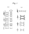
- Fig. 1 illustrates the arrangements of conventional rolling equipment rows, and the shapes of the grooves of the rolls attached to this rolling equipment. More specifically, Fig. 1-(a) shows an example in which two-high or three-high rolling mills are arranged from the roughing zone to the finishing zone, wherein I-beams and channels are formed by rolling, Figs.
- l-(b) and l-(c) show examples in which two-high or three-high rolling mills are arranged in the roughing zone and universal rolling mills are arranged in the intermediate rolling and finishing zones, wherein H-beams and channels are formed by rolling
- Fig. l-(d) shows an example in which two-high or three-high rolling mills and universal mills are appropriately arranged in the roughing, intermediate rolling and finishing zones, and straight web-type sheet piles are formed by rolling.
- exclusive rolls and accessory guides to be used from the roughing zone to the finishing zone should, in principle, be provided for the respective products independently, according to the kind and size of the products. Accordingly, as the sizes of the products are increased and the production range is broadened, the manufacturing costs are increased, and it becomes difficult to satisfy the needs of the customers in a simple way.
- H-beam As an example. Recently, production of so-called build-up H-beams through bonding and assembling steel sheets by welding has increased in line with the progress made in new welding techniques. This is because H-beams having optional sizes can be freely prepared according to customer needs. Typical products produced by this method are H-beams having a relatively small thickness and series of H-beams differing in flange thickness but having a constant web outer width.
- H-Beams having a constant web outer width but differing in flange thickness are adapted for bonding and working operation when used in a beam construction.
- these H-beams are not prepared according to conventional rolling methods, for the following reasons.
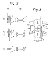
- Figure 2-(a) shows a typical example of a conventional H-beam forming rolling equipment row, which comprises one breakdown rolling mill 1 (BD), a subsequent mill group 2 (RU-E) of a 4-roll universal rolling mill (RU) and an edger rolling mill (E), and a finishing 4-roll universal rolling mill 3 (FU).
- BD breakdown rolling mill 1
- RU-E subsequent mill group 2
- E edger rolling mill
- FU finishing 4-roll universal rolling mill 3
- Figure 2-(b) shows shapes 4, 5, and 6 of rolled materials shaped by the rolling mills 1, 2 and 3, respectively.
- Figure 3 shows the relationship between the rolls and the rolled materials in the universal rolling method for forming H-beams. Because of the functional limitations of the universal rolling mill, sizes that can be freely changed by a pair of rolls of the same set during the rolling operation are restricted to a gap 9 between upper and lower horizontal rolls 7 and 8 and gaps 12 and 13 between left and right vertical rolls 10 and 11. Accordingly, the web thickness 9 and flange thicknesses 12 and 13 of the H-beam can be changed, but the inner width IW of the web must remain constant.
- a series of H-beams prepared according to the conventional rolling method are produced with a constant inner width of the web in which the inner width IW of the web is constant and the outer widths OW1 and OW2 of the web are changed according to changes of the flange thicknesses Tfl and Tf2, and it is very difficult for the conventional rolling method to prepare a series of products in which the outer width of the web is constant.
- a roll falling in contact with the inner side of the flange of the material and having an axis inclined at a predetermined angle 6h to a direction horizontally rectangular to the rolling direction is arranged, and engagement of the roll with the flange and web causes the web to be expanded in the widthwise direction.
- the roll may be arranged so that the roll falls in engagement with the upper and lower faces of the web.
- the axis of the roll may be vertically inclined at a predetermined angle ev to the horizontal plane.
- 8v is in the range of from 0 to 30° and preferably smaller than 5°.
- angle eh is in the range of 0 to 50° and preferably smaller than 15°.
- Figure 1 is a diagram of conventional rolling equipment rows and groove shapes of rolls of rolling mills for roughing, intermediate rolling and finishing zones
- Fig. 2 is a diagram of typical example of the conventional rolling equipment for forming H-beams, sectional shapes of materials rolled by roughing, intermediate and finishing rolling mills (BD), (RU-E), and (FU), and gives definitions of terms
- Fig. 3 is a diagram of the function of a universal rolling mill with reference to the relationship between a roll and a material rolled in the universal rolling method for forming H-beams
- Fig. 4 is a diagram of changes of sectional shapes in a series of products having a constant inner width of the web according to one embodiment of the present invention, and gives definitions of terms
- FIG. 5 is a diagram of an embodiment of a rolling equipment row in which sizing mills of the inclined roll system according to the present invention are arranged;
- Fig. 6-(a) is a front view of the roll construction showing the mechanism and function of the present invention, and Fig. 6-(b) is a side view of the roll construction seen obliquely from above;
- Fig. 7 is a plane view of one embodiment of a sizing mill of the inclined roll system according to the present invention, showing details of the function of the mill;
- Fig. 8 is a front view of one embodiment of a sizing mill of the inclined roll system according to the present invention, showing the structure in which the axis of the inclined roll can be three-dimensionally changed;
- FIG. 9 is a front view showing the operation of expanding the web width of an H-beam according to the conventional rolling method, showing the problems arising when rolling is performed while expanding the web width;
- Fig. 10 is a diagram showing in detail an embodiment of the present invention in which H-beams having a constant outer width of the web are formed by rolling;
- Fig. 11 is a diagram of an example of the calculation of conditions for expanding the web width of an H-beam in one embodiment of a sizing mill of the inclined roll system according to the present invention;
- Fig. 12 is a diagram showing parts of a product, the sizes of which are shown in Table 1.
- Fig. 5 shows an example of the rolling equipment row for the production of H-beams, in which reference numeral 14 represents an embodiment of a sizing mill of the inclined roll system. The function of this mill will now be described.
- the structure and function of rolls attached to the sizing mill of the inclined roll system are diagrammatically shown in Fig. 6.
- the sizing mill of the inclined roll system according to the present invention is characterized in that, as shown in the front view (a) and the side view (b) seen obliquely from above, the sizing mill comprises two upper inclined rolls 15 and 16 and two lower inclined rolls 15' and 16'.
- an inclined roll falls in contact with a web portion close to a flange of a material 17 having an H-shaped section on the inlet side and the width of the web is expanded by an oblique force generated by pressure of the roll on the web portion.
- the inner side face of the flange is expanded by the outer side face of the inclined roll to expand the width of the web.
- These two web width-expanding functions are exerted independently or synergistically, according to the quantity of expansion of the width of the web.
- the structure of the sizing mill of the inclined roll system according to the present invention differs greatly from the structure of the conventional rolling mill for the production of sections.
- the axes of the rolls are fixed so as to extend in a direction rectangular to the rolling direction.
- the directions of the axes S of the left and right rolls are not rectangular to the direction of advance of the material but are inclined at an angle 8h and are optionally changed.
- the left and right rolls are "inclined" in the form of "a wedge” to the direction of the material advance.
- these rolls are defined as inclined rolls.
- the rolls may be parallel to the horizontal plane, or they may be inclined at an optional angle 6v with respect to the horizontal plane.
- the outer side faces 19, 19', 20, and 20' of the inclined rolls 15, 15', 16, and 16' fall in contact with the inner side faces 21 and 22 of the flange of the material 17 on the inlet side, whereby a force expanding the inner side face of the flange horizontally in a direction rectangular to the direction of the material advance is imposed.
- This expanding force is another element of expanding the inner width IW1 of the web.
- the element of expanding the width of the web by pressing the web and the element of expanding the width of the web by acting on the flange exert their functions synergistically, whereby the web of the material to be rolled is easily and efficiently expanded.
- the inner width IW1 of the web of the material on the inlet side is expanded to IW2 in the material 23 on the outlet side and the outer width OWl of the web is expanded to OW2, whereby an expanded H-shaped section 24 is formed.
- Figure 9-(a) is a front view showing an example in which a material M to be rolled, which has a shape indicated by a solid line, is rolled according to the conventional rolling method while expanding the width of the web by pressing a part ⁇ w of the web.
- a metal flow deformation should be naturally caused in the part ⁇ W of the web to which a rolling force P is applied by the upper and lower horizontal rolls Ho and Hu.
- a metal flow is generated, not in the widthwise direction but in the direction of the material advance to be rolled, based on the propelling force transmitted from the roll only in the direction of the material advance, (2) a metal flow Sl is generated in the middle portion of the web, and (3) a metal flow So for expanding the width toward the exterior of the flange is generated.
- each of the metal flows (1) and (2) exerts an elongating action only in the advance direction of the material to be rolled, and only the metal flow (3) exerts an action of expanding the width of the web in a direction rectangular to the advance direction of the material to be rolled. Therefore, an unbalance of elongation is caused between the web and the flange which is not elongated in the advance direction because it is not rolled, with the result that undesirable phenomena such as waving of the web are caused.
- the restrained contact state can be maintained from the start of rolling to the end of rolling by the inclined faces of the rolls, and the size of the inner width of the web after expansion of the width is stable.
- Figure 9-(b) is a front view showing another example of expansion of the width of the web according to the conventional rolling method.
- a material having a bent web is provided so as to secure an allowance for expansion of the width in the web, and a rolling force P is supplied by the upper and lower horizontal rolls Ho and Hu of the conventional rolling sytem to expand the width of the web.
- a frictional force ⁇ P generated by the rolling force P acts as a force resistant against expansion of the width of the web while the bent portion of the web is rolled by applying the rolling force to the web by the upper and lower horizontal rolls Ho and Hu, and (2) the rolling is started in the restrained state where the inner side face Fl of the flange is kept in contact with the outer side faces of the horizontal rolls Ho and Hu, and then the inner side face Fl of the flange is not in contact with the side faces of the horizontal rolls and kept in the unrestrained free state until completion of the rolling.
- Figure 5 shows an example of a rolling equipment row for preparing a series of products of H-beams having a constant web outer width according to one embodiment of the present invention.
- the object of preparing H-beams having a constant web outer width is attained by arranging in combination an intermediate universal rolling mill (RU-E) 2, a sizing mill (SS) 14 of the inclined roll system, and a finishing rolling mill (FU) 3 as shown in Fig. 5.
- RU-E intermediate universal rolling mill
- SS sizing mill
- FU finishing rolling mill
- Fig. 10 Specific functions of the intermediate universal rolling mill (RU-E) 2, the sizing mill (SS) 14 of the inclined roll system, and the finishing rolling mill (FU) 3 are shown in Fig. 10.
- forming is conducted to sectional shapes 25 and 26 while taking the flange thickness and web thickness of the final product and the inner widths IW5, IW6, ... of the web into consideration, as shown in Fig. 10.
- the number of kinds of sectional shapes 25 and 26 thus formed is not particularly critical. Namely, since the material is rolled and shaped by the universal rolling mill at the intermediate rolling step, the web thickness and flange thickness can be freely changed, and a necessary number of different sectional shapes are formed according to the series of the product. However, the inner width IW1 of the web is constant, but the outer width OW1 of the web is not always constant.
- the rolled material having the sectional shapes 25 and 26 formed by the intermediate universal rolling mill 2 or having other shaped sections differing in the web thickness and flange thickness is fed to the sizing mill 14 of the inclined roll system.
- the rolled material is formed into a rolled material 27 having a necessary expanded inner width IW2 of the web expanded and rolled according to the series of the products by the sizing mill 14.
- This quantity 2a of expansion of the web width corresponds to the quantity 2a of the variation of the inner width of the web in the series of H-beam products having a constant outer width.
- the double of the variation a of the flange thickness is the variation 2 ⁇ of the inner width of the web of the product as follows:
- the quantity 2-a of necessary expansion of the web width varying according to the series of H-beam products having a constant outer width by the inclined rolls can be easily determined by adjusting (a) the inclination angle eh of the inclined rolls, (b) the distance L between the left and right inclined rolls, and (c) the rolling reduction of the web.
- the rolled material 27 individually prepared by the sizing mill of the inclined roll system according to the present invention is shaped and rolled to a section 28 having an inner width I4 of the web varying according to the series of the products by the finishing rolling mill 3 and is formed into a product 29 having a constant outer width of the web and an inner width IW6 of the web varying according to the series of the products.
- a product 31 having a maximum flange thickness and a minimum inner width of the web among the series of the products can be prepared by adjusting the quantity of expansion of the web width by the inclined rolls to zero, and, as is seen from the section 30 of this product 31, the inner width IW3 of the web corresponds to the inner width IW5 of the web of the product and is set at a value conforming to the inner width IW1 of the web of the sections 25 and 26 formed by the intermediate universal rolling mill (RU-E) 2.
- FIG. 11-(a) is a plane view of the inclined roll, in which the shape M of the material to be rolled and the state of expansion of the web width are indicated by dot lines
- Fig. ll-(b) is a front view of the inclined roll
- Fig. ll-(c) is a projection diagram of the inclined roll from the outer side face.
- the conditions for expanding the width of the web can be calculated according to the above formulae (1) and (2).
- the two elements af and aw for expanding the width of the web act synergistically, and hence, the web of the material to be rolled can be easily expanded.
- the quantity of expansion of the width of the web can be freely changed by adjusting the three factors L, 6h and ⁇ h/2 as indicated by the formulae (1) and (2).
- the foregoing coefficients can be appropriately selected according to the rolling conditions.
- the axis of the inclined roll may be parallel to the horizontal plane, or may be inclined at an optional angle ⁇ v to the horizontal plane.
- ⁇ v is adjusted to 0 in the foregoing embodiment, the pattern of the face of the contact between the outer side face of the inclined roll and the inner side face of the flange of the material to be rolled can be controlled by appropriately adjusting the values of the inclination angles ⁇ h and 6v.
- the width-expanding action due to 6h alone is utilized, the difference of the displacement in the widthwise direction of the flange, that is, the difference of the displacement between the portion close to the web and the top end of the flange, is increased, and the shape of the material to be rolled is readily deformed.
- an appropriate shape can be obtained by appropriately setting the 6v vlaue.
- the 8h value is in the range of 0 to 50° and preferably smaller than 15°.
- the 6v value is in the range of 0 to 30° and preferably smaller than 5°.
- the abrasion of the inclined rolls is not substantially different from the abrasion of rolls in the conventional rolling method, and even if certain abrasion is caused, the inclined rolls can resist a large quantity of rolling and be used for the production of a variety of products differing in size when the rolls are appropriately adjusted.
- H-beams having a constant outer width are produced.
- the present invention can be applied to the production of H-beams having a constant flange thickness but a varying outer width of the web, and two or three kinds of H-beams having a constant inner width of the web, which have heretofore been produced by mills, can be prepared individually without exchanging rolls and accessory members at the roughing and intermediate rolling steps.
- the application field of the present invention is very broad.
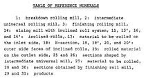
- Table 1 An example of the application range is shown in Table 1.
- Table 1-(a) shows some of the present standard sectional sizes stipulated in JIS
- Table l-(b) shows an example of the application range. Note, the symbols in Table l-(a) indicate the parts of the product shown in Fig. 12.
- Table 1-(a) in a series of H-beam products having nominal sizes of 400 x 200 mm and 450 x 200 mm, the inner width of the web is constant. For the production of these products, different rolls and accessory members are provided for the roughing, intermediate rolling, and finishing steps, respectively.
- Table 1-(b) there is shown an example of the application range of the rolling method using sizing mills of the inclined roll system, and it is demonstrated that if one set of rolls and accessory members are provided for each of the roughing and intermediate rolling steps, three kinds of H-beams differing in the size, that is, H-beams having a constant inner width of the web, H-beams having a constant outer width and H-beams having a novel intermediate size, can be prepared individually while maintaining the quality at the same level as in the conventional rolling method.
- the present invention has been described in detail mainly with reference to H-beams.
- the present invention can be applied to the production of other sections having a flange, such as channels, I-beams and sheet piles, by the web inner width-expanding rolling.
- the present invention can be applied to the productions of sections of not only hot steel but also aluminum or the like.
- the present invention relates to a rolling method and apparatus for forming sections having a flange, such as H-sections, channels , and other similar shapes.
- Fig. 1 illustrates the arrangements of conventional rnlling equipment rows, and the shapes of the grooves of the rolls attached to this rolling equipment. More specifically, Fig. l-(a) shows an example in which two-high or three-high rolling mills are arranged from the roughing zone to the finishing zone, wherein I-beams and channels are formed by rolling, Figs.
- Fig. l-(d) shows an example in which two-high or three-high rolling mills and universal mills are appropriately arranged in the roughing, intermediate rolling and finishing zones, and straight web-type sheet piles are formed by rolling.
- exclusive rolls and accessory guides to be used from the roughing zone to the finishing zone should, in principle, be provided for the respective products independently, according to the kind and size of the products. Accordingly, as the sizes of the products are increased and the production range is broadened, the manufacturing costs are increased, and it becomes difficult to satisfy the needs of the customers in a simple way.
- H-beam As an example. Recently, production of so-called build-up H-beams through bonding and assembling steel sheets by welding has increased in line with the progress made in new welding techniques. This is because H-beams having optional sizes can be freely prepared according to customer needs. Typical products produced by this method are H-beams having a relatively small thickness and series of H-beams differing in flange thickness but having a constant web outer width.
- H-Beams having a constant web outer width but differing in flange thickness are adapted for bonding and working operation when used in a beam construction.
- these H-beams are not prepared according to conventional rolling methods, for the following reasons.
- Figure 2-(a) shows a typical example of a conventional H-beam forming rolling equipment row, which comprises one breakdown rolling mill 1 (BD), a subsequent mill group 2 (RU-E) of a 4-roll universal rolling mill (RU) and an edger rolling mill (E), and a finishing 4-roll universal rolling mill 3 (FU).
- BD breakdown rolling mill 1
- RU-E subsequent mill group 2
- E edger rolling mill
- FU finishing 4-roll universal rolling mill 3
- Figure 2-(b) shows shapes 4, 5, and 6 of rolled materials shaped by the rolling mills 1, 2 and 3, respectively.
- Figure 3 shows the relationship between the rolls and the rolled materials in the universal rolling method for forming H-beams. Because of the functional limitations of the universal rolling mill, sizes that can be freely changed by a pair of rolls of the same set during the rolling operation are restricted to a gap 9 between upper and lower horizontal rolls 7 and 8 and gaps 12 and 13 between vertical rolls 1 0 and 11 and horizontal roll B 7 & 8.Accordingly, the web thickness 9 and flange thicknesses 12 and 13 of the H-beam can be changed, but the inner width IW of the web must remain constant.
- a series of H-beams prepared according to the conventional rolling method are produced with a constant inner width of the web in which the inner width IW of the web is constant and the outer widths OW1 and OW2 of the web are changed according to changes of the flange thicknesses Tfl and Tf2, and it is very difficult for the conventional rolling method to prepare a series of products in which the outer width of the web is constant.
- a roll falling in contact with the inner side of the flange of the material and having an axis inclined at a predetermined angle 6h to a direction horizontally rectangular to the rolling direction is arranged, and engagement of the roll with the flange and web causes the web to be expanded in the widthwise direction.
- the roll may be arranged so that the roll falls in engagement with the upper and lower faces of the web.
- the axis of the roll may be vertically inclined at a predetermined angle ev to the horizontal plane.
- ⁇ v is in the range of from 0 to 30° and preferably smaller than 5°.
- angle eh is in the range of 0 to 50° and preferably smaller than 15°.
- Figure 1 is a diagram of conventional rolling equipment rows and groove shapes of rolls of rolling mills for roughing, intermediate rolling and finishing zones
- Fig. 2 is a diagram of typical example of the conventional rolling equipment for forming H-beams, sectional shapes of materials rolled by roughing, intermediate and finishing rolling mills (BD), (RU-E), and (FU), and gives definitions of terms
- Fig. 3 is a diagram of the function of a universal rolling mill with reference to the relationship between a roll and a material rolled in the universal rolling method for forming H-beams
- Fig. 4 is a diagram of changes of sectional shapes in a series of products having a
Landscapes
- Engineering & Computer Science (AREA)
- Mechanical Engineering (AREA)
- Metal Rolling (AREA)
Abstract
Applications Claiming Priority (2)
| Application Number | Priority Date | Filing Date | Title |
|---|---|---|---|
| JP58077391A JPS59202101A (ja) | 1983-05-04 | 1983-05-04 | フランジを有する形材の圧延方法 |
| JP77391/83 | 1983-05-04 |
Publications (3)
| Publication Number | Publication Date |
|---|---|
| EP0142568A1 true EP0142568A1 (fr) | 1985-05-29 |
| EP0142568A4 EP0142568A4 (fr) | 1987-07-09 |
| EP0142568B1 EP0142568B1 (fr) | 1989-10-04 |
Family
ID=13632589
Family Applications (1)
| Application Number | Title | Priority Date | Filing Date |
|---|---|---|---|
| EP84901807A Expired EP0142568B1 (fr) | 1983-05-04 | 1984-05-04 | Procede et dispositif de calandrage de sections comportant un rebord |
Country Status (7)
| Country | Link |
|---|---|
| US (1) | US4685319A (fr) |
| EP (1) | EP0142568B1 (fr) |
| JP (1) | JPS59202101A (fr) |
| AU (1) | AU561482B2 (fr) |
| BR (1) | BR8406850A (fr) |
| DE (1) | DE3479970D1 (fr) |
| WO (1) | WO1984004263A1 (fr) |
Families Citing this family (17)
| Publication number | Priority date | Publication date | Assignee | Title |
|---|---|---|---|---|
| JPS62239482A (ja) * | 1986-04-10 | 1987-10-20 | Hitachi Electronics Eng Co Ltd | リ−ド/ライトヘツドのロ−デイング機構 |
| JPH0724841B2 (ja) * | 1986-05-30 | 1995-03-22 | 新日本製鐵株式会社 | フランジを有する形材の圧延方法 |
| JPS63315754A (ja) * | 1987-06-19 | 1988-12-23 | 三井建設株式会社 | 圧延h形鋼 |
| US5031435A (en) * | 1988-06-16 | 1991-07-16 | Kawasaki Steel Corporation | Adjustable width rolls for rolling mill |
| JPH0813361B2 (ja) * | 1988-09-20 | 1996-02-14 | 住友金属工業株式会社 | 平行フランジ形鋼の圧延方法 |
| US5056348A (en) * | 1989-06-01 | 1991-10-15 | Robertson-Ceco Corporation | Method of making a profiled sheet metal building unit |
| US4962622A (en) * | 1989-06-01 | 1990-10-16 | H. H. Robertson Company | Profiled sheet metal building unit and method for making the same |
| JPH0783885B2 (ja) * | 1990-01-12 | 1995-09-13 | 新日本製鐵株式会社 | ロール幅調整装置 |
| US5704998A (en) * | 1990-10-24 | 1998-01-06 | Consolidated Metal Products, Inc. | Hot rolling high-strength steel structural members |
| US5203193A (en) * | 1990-11-05 | 1993-04-20 | Kawasaki Steel Corporation | Method of rolling h-beams |
| DE19743093C1 (de) * | 1997-09-30 | 1998-12-17 | Thyssenkrupp Stahl Ag | Verfahren und Vorrichtung zum Herstellen eines Metallbandes mit über seine Breite verschieden dicken Bereichen |
| US6852181B2 (en) * | 2001-10-23 | 2005-02-08 | Consolidated Metal Products, Inc. | Flattened U-bolt and method |
| US7556454B2 (en) * | 2004-11-19 | 2009-07-07 | Nucor Yamato Steel Company | Irregularly surfaced H pile |
| RU2383401C2 (ru) * | 2007-10-01 | 2010-03-10 | ГОУ ВПО Пензенский государственный университет архитектуры и строительства | Двутавровый прокатный профиль |
| RU2411091C1 (ru) * | 2009-05-04 | 2011-02-10 | ГОУ ВПО Пензенский государственный университет архитектуры и строительства | Двутавровый горячекатаный колонный профиль |
| RU2486972C2 (ru) * | 2011-04-01 | 2013-07-10 | Государственное Образовательное Учреждение Высшего Профессионального Образования "Пензенский Государственный Университет Архитектуры И Строительства" | Способ проката двутаврового профиля сечения из низколегированной стали |
| JP6441159B2 (ja) | 2015-04-27 | 2018-12-19 | 三菱重工業株式会社 | 圧延加工装置 |
Family Cites Families (10)
| Publication number | Priority date | Publication date | Assignee | Title |
|---|---|---|---|---|
| US276322A (en) * | 1883-04-24 | ac aster | ||
| DE469821C (de) * | 1928-12-21 | Hermann Oberschulte | Walzvorrichtung fuer Walzgut mit unterschnittenen Profilen | |
| US1243051A (en) * | 1911-06-15 | 1917-10-16 | Louis F Dieter | Method or process of rolling or forming car-wheels or other circular bodies. |
| US2361729A (en) * | 1939-02-18 | 1944-10-31 | Nedden Gerhard Zur | Method of rolling strip irons |
| FR1528619A (fr) * | 1966-09-08 | 1968-06-14 | Wendel & Cie De | Procédé pour l'ébauchage de grosses poutrelles de grande largeur |
| GB1255240A (en) * | 1969-11-18 | 1971-12-01 | Anaconda American Brass Co | Method of producing dual gauge strip |
| SU505447A1 (ru) * | 1974-11-28 | 1976-03-05 | Способ прокатки листов | |
| JPS5931402B2 (ja) * | 1976-12-30 | 1984-08-02 | 新日本製鐵株式会社 | 粗形鋼片の胴部を引き伸ばす装置 |
| DE2813636C3 (de) * | 1978-03-30 | 1980-10-30 | Theodor Wuppermann Gmbh, 5090 Leverkusen | Verfahren und Einrichtung zur Herstellung von Profilen aus Metall, vornehmlich von Stahlprofilen |
| DE3012702A1 (de) * | 1980-04-01 | 1981-10-08 | Proizvodstvennoe ob"edinenie Uralmaš, Sverdlovsk | Verfahren zur herstellung von doppel-t-traegern |
-
1983
- 1983-05-04 JP JP58077391A patent/JPS59202101A/ja active Granted
-
1984
- 1984-05-04 US US06/693,267 patent/US4685319A/en not_active Expired - Lifetime
- 1984-05-04 BR BR8406850A patent/BR8406850A/pt not_active IP Right Cessation
- 1984-05-04 AU AU28645/84A patent/AU561482B2/en not_active Expired
- 1984-05-04 WO PCT/JP1984/000226 patent/WO1984004263A1/fr not_active Ceased
- 1984-05-04 EP EP84901807A patent/EP0142568B1/fr not_active Expired
- 1984-05-04 DE DE8484901807T patent/DE3479970D1/de not_active Expired
Also Published As
| Publication number | Publication date |
|---|---|
| US4685319A (en) | 1987-08-11 |
| BR8406850A (pt) | 1985-03-19 |
| JPS59202101A (ja) | 1984-11-15 |
| EP0142568A4 (fr) | 1987-07-09 |
| AU2864584A (en) | 1984-11-19 |
| JPH0342122B2 (fr) | 1991-06-26 |
| WO1984004263A1 (fr) | 1984-11-08 |
| DE3479970D1 (en) | 1989-11-09 |
| AU561482B2 (en) | 1987-05-07 |
| EP0142568B1 (fr) | 1989-10-04 |
Similar Documents
| Publication | Publication Date | Title |
|---|---|---|
| EP0142568B1 (fr) | Procede et dispositif de calandrage de sections comportant un rebord | |
| EP0498733B1 (fr) | Procédé pour laminer des profilés en acier | |
| US4385512A (en) | Tandem rolling mill train for metal plate and sheet | |
| EP0484854B1 (fr) | Procédé pour le laminage de poutrelles en H | |
| JPS59133902A (ja) | H形鋼の熱間圧延方法 | |
| JPH0318521B2 (fr) | ||
| CA1247405A (fr) | Methode et dispositif de laminage pour la mise en forme de sections a bride | |
| JP3310427B2 (ja) | H形鋼の圧延方法 | |
| JP3183077B2 (ja) | カットt形鋼の製造方法及び装置 | |
| JP3272856B2 (ja) | フランジを有する形鋼の圧延方法 | |
| EP0760263A1 (fr) | Procede et dispositif de laminage a chaud d'acier a profil en h | |
| JP2720750B2 (ja) | H形鋼の圧延機列 | |
| EP0559539A1 (fr) | Procédé pour la fabrication de poutrelles d'acier en H | |
| JPH0364201B2 (fr) | ||
| JPH026001A (ja) | 形鋼の圧延方法 | |
| JPH02112801A (ja) | フランジ付き形鋼のユニバーサル圧延方法と圧延機 | |
| JP3988586B2 (ja) | フランジ内面突起付形鋼の製造方法及びそれに使用される仕上ユニバーサル圧延機 | |
| JP3272879B2 (ja) | フランジを有する形鋼の圧延方法 | |
| KR100214730B1 (ko) | 에이치형 비임의 압연방법 | |
| JP2804346B2 (ja) | 形鋼の圧延方法 | |
| JPS62263801A (ja) | 中心偏りの小さなh形鋼の圧延方法およびh形鋼用ユニバ−サル圧延機 | |
| JPWO1995017269A1 (ja) | H形鋼の製造方法 | |
| JP2762904B2 (ja) | H形鋼の圧延方法 | |
| JPH06210302A (ja) | フランジを有する形鋼の圧延方法 | |
| JPH02147102A (ja) | H形鋼の圧延方法および圧延機 |
Legal Events
| Date | Code | Title | Description |
|---|---|---|---|
| PUAI | Public reference made under article 153(3) epc to a published international application that has entered the european phase |
Free format text: ORIGINAL CODE: 0009012 |
|
| 17P | Request for examination filed |
Effective date: 19850125 |
|
| AK | Designated contracting states |
Designated state(s): DE FR GB |
|
| A4 | Supplementary search report drawn up and despatched |
Effective date: 19870709 |
|
| 17Q | First examination report despatched |
Effective date: 19880519 |
|
| GRAA | (expected) grant |
Free format text: ORIGINAL CODE: 0009210 |
|
| AK | Designated contracting states |
Kind code of ref document: B1 Designated state(s): DE FR GB |
|
| REF | Corresponds to: |
Ref document number: 3479970 Country of ref document: DE Date of ref document: 19891109 |
|
| ET | Fr: translation filed | ||
| PLBE | No opposition filed within time limit |
Free format text: ORIGINAL CODE: 0009261 |
|
| STAA | Information on the status of an ep patent application or granted ep patent |
Free format text: STATUS: NO OPPOSITION FILED WITHIN TIME LIMIT |
|
| 26N | No opposition filed | ||
| REG | Reference to a national code |
Ref country code: GB Ref legal event code: IF02 |
|
| PGFP | Annual fee paid to national office [announced via postgrant information from national office to epo] |
Ref country code: GB Payment date: 20030430 Year of fee payment: 20 |
|
| PGFP | Annual fee paid to national office [announced via postgrant information from national office to epo] |
Ref country code: FR Payment date: 20030508 Year of fee payment: 20 |
|
| PGFP | Annual fee paid to national office [announced via postgrant information from national office to epo] |
Ref country code: DE Payment date: 20030515 Year of fee payment: 20 |
|
| PG25 | Lapsed in a contracting state [announced via postgrant information from national office to epo] |
Ref country code: GB Free format text: LAPSE BECAUSE OF EXPIRATION OF PROTECTION Effective date: 20040503 |
|
| REG | Reference to a national code |
Ref country code: GB Ref legal event code: PE20 |