EP0142685A2 - Mâchoires ou coquilles pour un appareil hydraulique de fracturation mécanique de la roche - Google Patents
Mâchoires ou coquilles pour un appareil hydraulique de fracturation mécanique de la roche Download PDFInfo
- Publication number
- EP0142685A2 EP0142685A2 EP84111848A EP84111848A EP0142685A2 EP 0142685 A2 EP0142685 A2 EP 0142685A2 EP 84111848 A EP84111848 A EP 84111848A EP 84111848 A EP84111848 A EP 84111848A EP 0142685 A2 EP0142685 A2 EP 0142685A2
- Authority
- EP
- European Patent Office
- Prior art keywords
- pressure jaws
- pressure
- jaws
- sliding wedge
- cylinder
- Prior art date
- Legal status (The legal status is an assumption and is not a legal conclusion. Google has not performed a legal analysis and makes no representation as to the accuracy of the status listed.)
- Granted
Links
Images


Classifications
-
- E—FIXED CONSTRUCTIONS
- E21—EARTH OR ROCK DRILLING; MINING
- E21C—MINING OR QUARRYING
- E21C37/00—Other methods or devices for dislodging with or without loading
- E21C37/04—Other methods or devices for dislodging with or without loading by devices with parts pressed mechanically against the wall of a borehole or a slit
Definitions
- the invention relates to pressure jaws or shells for a device for the mechanical dismantling of rock with a cylinder in which a hydraulically actuated piston with a piston rod is arranged to be longitudinally movable, by means of which a sliding wedge arranged between the pressure jaws can be displaced, the pressure jaws which can be inserted into boreholes in the cylinder block or in a detachably arranged on this lower cylinder part and since Lich limitedly movable and have a slope corresponding to the inclination of the sliding wedge on their sides facing the sliding wedge.
- Stone splitting devices of the type mentioned are generally known (DE-AS 1 254 562; DE-PS 1 783 155). Forces of the order of magnitude of 300 t and more can be generated with such relatively handy devices. The use of explosives is no longer necessary to remove rocks or break them up.
- the present invention has for its object to provide pressure jaws or shells for a device of the type mentioned, which can be used even with relative displacements of the rock in the direction of the row of holes, so that manually driven riving knife can be dispensed with.
- the pressure jaws are approximately spade or hammer-shaped.
- Fixing the cylinder or cylinder-bottom part need not be rotated or have at least as much pivot away from the sliding wedge that an F ixierfitung the D ruck bake up to 90 °.
- An advantageous embodiment of a stone splitting device is described below, which is particularly suitable for the use of the pressure jaws designed according to the invention.
- the sliding wedge is spade or hammer-shaped in accordance with the pressure jaws.
- the slide wedge preferably has a width corresponding to the width of the insert section of the pressure jaws over its entire length protruding from the cylinder or lower cylinder part in the retracted or retracted state.
- the width of the pressure jaws in the lower area of application corresponds to at least approximately twice the borehole diameter.
- the width of D is preferably smoothly baking in this area about three times borehole diameter.
- the measures according to claim 5 serve to further increase the stability of the "pressure jaw / sliding wedge" unit.
- Lower part 2 is guided in a longitudinally displaceable manner.
- a guide sleeve 5 made of wear-resistant bearing material is arranged at the free lower end of the piston rod 3. The bearing sleeve 5 is locked at the free lower end of the piston rod 3 by means of a retaining pin 31 and a helical spring 6.
- a sliding wedge 18 is fastened by means of a retaining bolt 4 which penetrates both it and the piston rod 3.
- the sliding wedge 18 acts on pressure jaws or shells 17 which can be inserted into boreholes, can be displaced laterally to a limited extent and are releasably connected to the lower cylinder part 2 by means of reinforced head pieces 32 and which have a slope corresponding to the inclination of the sliding wedge.
- the pressure jaws 17 are suspended on cross bolts 10 arranged diametrically in the lower cylinder part 2 and are elastically fixed and centered with spring elements 13, 14, 24 to be described in more detail.
- the laterally limited displaceability of the pressure jaws 17 is achieved in that they are mounted displaceably on the cross bolt 10, specifically on the inner portions 20 of the Cross bolts 10, which in the embodiment shown have a slightly smaller diameter than the outer sections 21, which serve as a threaded and bearing part.
- the cross bolts 10 are arranged displaceably in the longitudinal direction of the bolt between an outer pressure jaw release position (in FIG. 1 below) and an inner pressure jaw suspension position (FIG. 1 above) such that in the former the pressure jaws 17 are downward - in FIG. 1 to the right - Can be pulled out of the cylinder base 2 without rotation about its longitudinal axes or lateral pivoting and vice versa.
- the two transverse bolts 10 can be moved in the lower cylinder part 2 in the manner of a screw between the pressure jaw release position and the pressure jaw suspension position, with an approximately helical groove 23 on the circumference of the outer cross bolt portions 21 of larger diameter is milled into which a guide pin 11 engages, the rotational movement of the cross bolts 10 being limited by the end ends of the groove 23.
- the cross bolts 10 are locked in the pressure jaw release position or pressure jaw suspension position by a ball catch 7, 8, 9, the spring-loaded pressure ball 9 of which engages in corresponding recesses on the circumference of the cross bolt 10.
- the bias of the spring 8 loading the locking ball 9 can be varied by means of a threaded pin 7 acting on the end of the spring 8 opposite the ball 9.
- the bearing sleeve 19 for the cross bolt 10 is in the illustrated embodiment formed in one piece and consists of a highly wear-resistant bearing material, such as corrosion-resistant steel or a sintered material.
- the bearing sleeve 19 is shrunk in the lower cylinder part 2.
- spring elements are provided which, for example, consist of two pressure bolts which are arranged in the lower region of the lower cylinder part 2 and are pressed by pressure springs against the outer sides of the pressure jaws 17 and which simultaneously guide the D jerk 17 and thus serve the intermediate wedge 18.
- the spring elements for centering the pressure jaws 17 consist of two centering bolts 13 with bent ends 24 arranged in the cylinder lower part 2 for the longitudinal extension of the pressure jaws 17, which can be displaced against the action of prestressed springs 14 and which end under the action of the springs 14 rest on the outside of a pressure jaw 17, the centering bolts 13 designed in this way being rotatable about their own axis, so that their bent ends 24 for releasing the pressure jaws 17 are located approximately parallel to the latter (see FIGS. 2 to 5). 2 and 3 that the centering bolts 13 always hold the pressure jaws 17 in contact with the two inclined surfaces of the sliding wedge 18.
- the centering bolts 13 are rotated by the interaction of the bent ends 24 with correspondingly designed control sections on the pressure bake 17 when pulling them out or inserting them into or into the cylinder lower part 2.
- the control sections on the pressure jaws 17 are recesses 25 arranged on the outer sides of the pressure jaws 17, into which the bent ends 24 of the centering bolts 13 project laterally (see FIG.
- the sides of the recesses 25 facing the free end faces of the bent ends 24 of the centering bolts 13 being cam surfaces, which are defined by a straight linear section 26 starting from the head-side end of the pressure jaws 17 and a subsequent lower section 27 , which is limited in the direction of the free end of the pressure jaws 17 by a stop surface 28, which extends approximately transversely to the longitudinal direction of the pressure jaws, for the bent end 24 of the associated centering bolt 13 (FIGS. 4 and 5).
- the cam surfaces 25 have approximately the contour of a crane hook.
- the bent end 24 of the centering pin 13 can be pivoted through an angle of approximately 60 ° from a position transversely to the longitudinal direction of the pressure jaws into a position towards the free end of the pressure jaws 17, it being in the latter Position when pulling out the associated pressure jaw 17 from the lower cylinder part 2 can be brought by the flat cam section 26.
- the free section of the bent end 24 of the centering bolt 13 still protrudes somewhat into the pressure jaw receiving space 33, so that it can be detected by the stop surface 28 of the lower cam portion 27 when a pressure jaw is inserted into the lower cylinder part 2 or into this receiving space 33 and can be pivoted back into the position transverse to the longitudinal direction of the pressure jaw from a position in FIG. 5 to a position according to FIG. 4.
- the pivoting back of the bent end 24 into a position according to FIG. 4 is limited by a corresponding stop in the centering pin bearing 12.
- the centering spring is held in the centering pin bearing 12 by a washer 15 and screw 16.
- the circumferential grooves 23 of the two transverse bolts 10 each have an incline in the same direction.
- the cross bolts 10 are actuated or rotated by means of a screwdriver which can be inserted into a corresponding recess 56 on the outer end faces of the two cross bolts.
- the slope of the two circumferential grooves 23 is preferably directed in opposite directions, so that the outer end faces of the two cross bolts 10 are coupled to one another by means of a bracket 22 and thus both cross bolts simultaneously by pivoting movement of the bracket 22 about the common cross bolt center axis into the inner pressure jaws -Installation position or external pressure release position can be moved.
- the two legs of the bracket 22 are designed to be flexible, so that they can follow the translational movement of the two transverse bolts 10 unhindered.
- the free end faces of the bent ends 24 of the centering pin 13 are curved in the perpendicular to the plane defined by the bent centering pin in order to prevent jamming when the pressure jaws 17 are inserted between the bent ends 24 and the stop surface 28 avoid.
- the curved end faces of the bent ends 24 of the centering bolts 13 are identified in FIGS. 4 and 5 with the reference number 80. It is ensured by this design of the free end faces of the bent ends 24 of the centering bolts 13 that when the pressure jaws 17 are inserted into the cylinder lower part 2 or into the pressure jaw receiving space 33 in the cylinder lower part 2 on which Longitudinally extending stop surface 28 slides easily.
- the recess 25 on the outer sides of the pressure jaws 17 is open on three sides, namely at the head end, on the outside and on the the centering pin 13, 24 side facing.
- the recess 25 practically represents a cut corner at the head end of the pressure jaws 17.
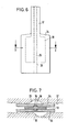
- the stone splitting device described is suitable, inter alia, for the use of approximately spade-shaped pressure jaws, as shown in FIGS. 6 and 7.
- the sliding wedge 18 is formed like a spade in accordance with the pressure jaws 17, the width corresponding approximately to the width of the lower insert area 34 of the pressure jaws 17.
- the sliding wedge is also spade-shaped. As a rule, you will even use a normal, relatively narrow sliding wedge that is adapted to the width of the pressure jaws normally used.
- the two opposite sliding surfaces of the sliding wedge 18 each have an axially extending spring 35 and the associated sliding or inclined surfaces of the pressure jaws 17 have corresponding grooves 36. In this way, a relative lateral displacement of the between the pressure jaws 17 and the sliding wedge 18 is reliably avoided during use.
- FIG. 7 a displacement of the rock in the direction of the fracture or in the direction of the row of boreholes is shown in FIG. 7. It is seen that in spite of this shift, the stone gap device thanks to the inventive design D ruck bake readily be inserted.
- the outer sides of the pressure jaws are preferably roughened, ribbed or knurled in the lower insert region 34 in order to prevent them sliding sideways within the gap 37.
- the width of the pressure jaws 17 in the lower area of use 34 corresponds to at least approximately twice the borehole diameter.
- the handling in particular the insertion of the pressure jaws 17 into the gap 37, can be facilitated by the fact that the outer sides of the pressure jaws 17 facing away from one another in the assembled state are slightly convex in section transversely to the axial direction.
- the lower area of use 34 of the pressure jaws 17 can also be hammer-shaped or sickle-shaped. This essentially depends on the depth of use and the rock to be broken. However, the most stable and effective is a spade-like shape of the pressure jaws.
Landscapes
- Engineering & Computer Science (AREA)
- Mining & Mineral Resources (AREA)
- Life Sciences & Earth Sciences (AREA)
- General Life Sciences & Earth Sciences (AREA)
- Geochemistry & Mineralogy (AREA)
- Geology (AREA)
- Earth Drilling (AREA)
- Drilling And Exploitation, And Mining Machines And Methods (AREA)
- Crushing And Grinding (AREA)
- Processing Of Stones Or Stones Resemblance Materials (AREA)
Priority Applications (1)
| Application Number | Priority Date | Filing Date | Title |
|---|---|---|---|
| AT84111848T ATE40845T1 (de) | 1983-10-21 | 1984-10-03 | Druckbacken bzw. -schalen fuer ein hydraulisch betaetigbares geraet zum mechanischen zerlegen von gestein. |
Applications Claiming Priority (2)
| Application Number | Priority Date | Filing Date | Title |
|---|---|---|---|
| DE3338368A DE3338368C2 (de) | 1983-10-21 | 1983-10-21 | Druckbacken bzw. -schalen für ein hydraulisch betätigbares Gerät zum mechanischen Zerlegen von Gestein |
| DE3338368 | 1983-10-21 |
Publications (3)
| Publication Number | Publication Date |
|---|---|
| EP0142685A2 true EP0142685A2 (fr) | 1985-05-29 |
| EP0142685A3 EP0142685A3 (en) | 1986-11-20 |
| EP0142685B1 EP0142685B1 (fr) | 1989-02-15 |
Family
ID=6212472
Family Applications (1)
| Application Number | Title | Priority Date | Filing Date |
|---|---|---|---|
| EP84111848A Expired EP0142685B1 (fr) | 1983-10-21 | 1984-10-03 | Mâchoires ou coquilles pour un appareil hydraulique de fracturation mécanique de la roche |
Country Status (3)
| Country | Link |
|---|---|
| EP (1) | EP0142685B1 (fr) |
| AT (1) | ATE40845T1 (fr) |
| DE (2) | DE3338368C2 (fr) |
Cited By (1)
| Publication number | Priority date | Publication date | Assignee | Title |
|---|---|---|---|---|
| FR2655587A1 (fr) * | 1989-12-11 | 1991-06-14 | Koehl Jean Marie | Tete d'outil a percussion tel que beche, burin, etc... avec gorge d'evacuation des poussieres. |
Families Citing this family (1)
| Publication number | Priority date | Publication date | Assignee | Title |
|---|---|---|---|---|
| CN103967491B (zh) * | 2014-04-21 | 2016-08-17 | 宁波奉金东旭工程机械科技有限公司 | 液压式岩石破碎枪 |
Family Cites Families (5)
| Publication number | Priority date | Publication date | Assignee | Title |
|---|---|---|---|---|
| US2328661A (en) * | 1941-03-10 | 1943-09-07 | Joseph F Maloney | Breaking device |
| DE1254562B (de) * | 1964-07-28 | 1967-11-23 | Helmut Darda | Hydraulisches Steinsprenggeraet |
| DE1239259B (de) * | 1965-11-29 | 1967-04-27 | Wilhelm Dahmen Tauch Und Spren | Treibmeissel fuer das Auseinandertreiben von mit Bohrloechern vorbereiteten Felsmassen |
| DE1783155C2 (de) * | 1965-12-07 | 1975-05-15 | Helmut 7712 Blumberg Darda | Hydraulisches Steinsprenggerät |
| DE3131639C2 (de) * | 1981-08-11 | 1984-12-20 | H. Bieri AG Maschinenfabrik, Liebefeld, Bern | Hydraulisches Spaltgerät |
-
1983
- 1983-10-21 DE DE3338368A patent/DE3338368C2/de not_active Expired
-
1984
- 1984-10-03 AT AT84111848T patent/ATE40845T1/de not_active IP Right Cessation
- 1984-10-03 EP EP84111848A patent/EP0142685B1/fr not_active Expired
- 1984-10-03 DE DE8484111848T patent/DE3476776D1/de not_active Expired
Cited By (1)
| Publication number | Priority date | Publication date | Assignee | Title |
|---|---|---|---|---|
| FR2655587A1 (fr) * | 1989-12-11 | 1991-06-14 | Koehl Jean Marie | Tete d'outil a percussion tel que beche, burin, etc... avec gorge d'evacuation des poussieres. |
Also Published As
| Publication number | Publication date |
|---|---|
| ATE40845T1 (de) | 1989-03-15 |
| EP0142685B1 (fr) | 1989-02-15 |
| EP0142685A3 (en) | 1986-11-20 |
| DE3338368A1 (de) | 1985-05-02 |
| DE3476776D1 (en) | 1989-03-23 |
| DE3338368C2 (de) | 1985-10-31 |
Similar Documents
| Publication | Publication Date | Title |
|---|---|---|
| DE2832429C2 (fr) | ||
| EP0220334A1 (fr) | Support de feuilles, accessoire de bureau, de planche à dessin, d'écran ou similaire | |
| DE2644290A1 (de) | Klemmvorrichtung | |
| DE827050C (de) | Loesbare Verbindung von Kappen fuer den Strebausbau | |
| DE3119605C2 (de) | Vorrichtung zum unterschneidenden Räumen von zylindrischen Bohrlöchern | |
| DE2915197C2 (de) | Werkzeug, insbesondere Bolzenziehergerät | |
| EP0142685B1 (fr) | Mâchoires ou coquilles pour un appareil hydraulique de fracturation mécanique de la roche | |
| DE2364509C2 (de) | Montagezange zum Spreizen oder Zusammendrücken von offenen Sicherungsringen | |
| DE2336063B1 (de) | Hydraulisch betaetigtes Geraet zum mechanischen Zerlegen von Gestein | |
| DE1481809B2 (de) | Vorrichtung zum Aufstellen und Umlegen von Masten, insbesondere eines Baukranmastes | |
| DE3303369A1 (de) | Wasserpumpenzange | |
| DE3228433C2 (de) | Steinspaltgerät zum mechanischen Zerlegen von Gestein | |
| AT390024B (de) | Klemmeinrichtung fuer eine auf einer saeule verschiebbare platte | |
| DE745160C (de) | Eiserner Grubenstempel | |
| DE2124675A1 (de) | Mechanische Anhebevorrichtung | |
| DE7430652U (de) | Hohlbohrkrone | |
| DE3152416A1 (en) | Torque transmitting device | |
| DE3249246C2 (de) | Hydraulisch betätigbares Gerät zum mechanischen Zerlegen von Gestein | |
| DE2237651C3 (de) | Bandspanner | |
| DE917542C (de) | Stabfoermiger, schraubenfoermig verdrillter Gebirgsanker | |
| DE3124896C2 (de) | Kettenschäkel für Rundgliederketten | |
| DE828690C (de) | Nachgiebiger Grubenstempel | |
| DE622498C (de) | Schubstangenverschluss fuer Maehmaschinen | |
| DE4329582C1 (de) | Vorrichtung zum Herstellen von Längskerben in der Wandung eines Bohrlochs | |
| DE2557097A1 (de) | Vorrichtung zum feststellen von tueren, toren, klappen u.dgl. in beliebiger stellung |
Legal Events
| Date | Code | Title | Description |
|---|---|---|---|
| PUAI | Public reference made under article 153(3) epc to a published international application that has entered the european phase |
Free format text: ORIGINAL CODE: 0009012 |
|
| AK | Designated contracting states |
Designated state(s): AT BE CH DE FR GB IT LI LU NL SE |
|
| PUAL | Search report despatched |
Free format text: ORIGINAL CODE: 0009013 |
|
| AK | Designated contracting states |
Kind code of ref document: A3 Designated state(s): AT BE CH DE FR GB IT LI LU NL SE |
|
| 17P | Request for examination filed |
Effective date: 19870115 |
|
| 17Q | First examination report despatched |
Effective date: 19871019 |
|
| ITF | It: translation for a ep patent filed | ||
| GRAA | (expected) grant |
Free format text: ORIGINAL CODE: 0009210 |
|
| AK | Designated contracting states |
Kind code of ref document: B1 Designated state(s): AT BE CH DE FR GB IT LI LU NL SE |
|
| PG25 | Lapsed in a contracting state [announced via postgrant information from national office to epo] |
Ref country code: NL Effective date: 19890215 Ref country code: BE Effective date: 19890215 |
|
| REF | Corresponds to: |
Ref document number: 40845 Country of ref document: AT Date of ref document: 19890315 Kind code of ref document: T |
|
| REF | Corresponds to: |
Ref document number: 3476776 Country of ref document: DE Date of ref document: 19890323 |
|
| GBT | Gb: translation of ep patent filed (gb section 77(6)(a)/1977) | ||
| NLV1 | Nl: lapsed or annulled due to failure to fulfill the requirements of art. 29p and 29m of the patents act | ||
| ET | Fr: translation filed | ||
| PG25 | Lapsed in a contracting state [announced via postgrant information from national office to epo] |
Ref country code: LU Free format text: LAPSE BECAUSE OF NON-PAYMENT OF DUE FEES Effective date: 19891031 Ref country code: LI Effective date: 19891031 Ref country code: CH Effective date: 19891031 |
|
| PLBE | No opposition filed within time limit |
Free format text: ORIGINAL CODE: 0009261 |
|
| STAA | Information on the status of an ep patent application or granted ep patent |
Free format text: STATUS: NO OPPOSITION FILED WITHIN TIME LIMIT |
|
| 26N | No opposition filed | ||
| REG | Reference to a national code |
Ref country code: CH Ref legal event code: PL |
|
| PGFP | Annual fee paid to national office [announced via postgrant information from national office to epo] |
Ref country code: GB Payment date: 19900921 Year of fee payment: 7 |
|
| PGFP | Annual fee paid to national office [announced via postgrant information from national office to epo] |
Ref country code: AT Payment date: 19901011 Year of fee payment: 7 |
|
| PGFP | Annual fee paid to national office [announced via postgrant information from national office to epo] |
Ref country code: SE Payment date: 19901012 Year of fee payment: 7 Ref country code: FR Payment date: 19901012 Year of fee payment: 7 |
|
| ITTA | It: last paid annual fee | ||
| PGFP | Annual fee paid to national office [announced via postgrant information from national office to epo] |
Ref country code: DE Payment date: 19901129 Year of fee payment: 7 |
|
| PG25 | Lapsed in a contracting state [announced via postgrant information from national office to epo] |
Ref country code: GB Effective date: 19911003 Ref country code: AT Effective date: 19911003 |
|
| PG25 | Lapsed in a contracting state [announced via postgrant information from national office to epo] |
Ref country code: SE Effective date: 19911004 |
|
| GBPC | Gb: european patent ceased through non-payment of renewal fee | ||
| PG25 | Lapsed in a contracting state [announced via postgrant information from national office to epo] |
Ref country code: FR Effective date: 19920630 |
|
| PG25 | Lapsed in a contracting state [announced via postgrant information from national office to epo] |
Ref country code: DE Effective date: 19920701 |
|
| REG | Reference to a national code |
Ref country code: FR Ref legal event code: ST |
|
| EUG | Se: european patent has lapsed |
Ref document number: 84111848.2 Effective date: 19920510 |