EP0142815A2 - Laser mit stabilisierter externer passiver Kavität - Google Patents
Laser mit stabilisierter externer passiver Kavität Download PDFInfo
- Publication number
- EP0142815A2 EP0142815A2 EP84113707A EP84113707A EP0142815A2 EP 0142815 A2 EP0142815 A2 EP 0142815A2 EP 84113707 A EP84113707 A EP 84113707A EP 84113707 A EP84113707 A EP 84113707A EP 0142815 A2 EP0142815 A2 EP 0142815A2
- Authority
- EP
- European Patent Office
- Prior art keywords
- cavity
- laser
- external
- mirror
- passive
- Prior art date
- Legal status (The legal status is an assumption and is not a legal conclusion. Google has not performed a legal analysis and makes no representation as to the accuracy of the status listed.)
- Granted
Links
Images


Classifications
-
- H—ELECTRICITY
- H01—ELECTRIC ELEMENTS
- H01S—DEVICES USING THE PROCESS OF LIGHT AMPLIFICATION BY STIMULATED EMISSION OF RADIATION [LASER] TO AMPLIFY OR GENERATE LIGHT; DEVICES USING STIMULATED EMISSION OF ELECTROMAGNETIC RADIATION IN WAVE RANGES OTHER THAN OPTICAL
- H01S3/00—Lasers, i.e. devices using stimulated emission of electromagnetic radiation in the infrared, visible or ultraviolet wave range
- H01S3/05—Construction or shape of optical resonators; Accommodation of active medium therein; Shape of active medium
- H01S3/08—Construction or shape of optical resonators or components thereof
- H01S3/081—Construction or shape of optical resonators or components thereof comprising three or more reflectors
- H01S3/082—Construction or shape of optical resonators or components thereof comprising three or more reflectors defining a plurality of resonators, e.g. for mode selection or suppression
-
- H—ELECTRICITY
- H01—ELECTRIC ELEMENTS
- H01S—DEVICES USING THE PROCESS OF LIGHT AMPLIFICATION BY STIMULATED EMISSION OF RADIATION [LASER] TO AMPLIFY OR GENERATE LIGHT; DEVICES USING STIMULATED EMISSION OF ELECTROMAGNETIC RADIATION IN WAVE RANGES OTHER THAN OPTICAL
- H01S3/00—Lasers, i.e. devices using stimulated emission of electromagnetic radiation in the infrared, visible or ultraviolet wave range
- H01S3/10—Controlling the intensity, frequency, phase, polarisation or direction of the emitted radiation, e.g. switching, gating, modulating or demodulating
- H01S3/13—Stabilisation of laser output parameters, e.g. frequency or amplitude
- H01S3/139—Stabilisation of laser output parameters, e.g. frequency or amplitude by controlling the mutual position or the reflecting properties of the reflectors of the cavity, e.g. by controlling the cavity length
-
- G—PHYSICS
- G01—MEASURING; TESTING
- G01N—INVESTIGATING OR ANALYSING MATERIALS BY DETERMINING THEIR CHEMICAL OR PHYSICAL PROPERTIES
- G01N15/00—Investigating characteristics of particles; Investigating permeability, pore-volume or surface-area of porous materials
- G01N15/02—Investigating particle size or size distribution
- G01N15/0205—Investigating particle size or size distribution by optical means
-
- G—PHYSICS
- G01—MEASURING; TESTING
- G01N—INVESTIGATING OR ANALYSING MATERIALS BY DETERMINING THEIR CHEMICAL OR PHYSICAL PROPERTIES
- G01N21/00—Investigating or analysing materials by the use of optical means, i.e. using sub-millimetre waves, infrared, visible or ultraviolet light
- G01N21/17—Systems in which incident light is modified in accordance with the properties of the material investigated
- G01N21/25—Colour; Spectral properties, i.e. comparison of effect of material on the light at two or more different wavelengths or wavelength bands
- G01N21/31—Investigating relative effect of material at wavelengths characteristic of specific elements or molecules, e.g. atomic absorption spectrometry
- G01N21/39—Investigating relative effect of material at wavelengths characteristic of specific elements or molecules, e.g. atomic absorption spectrometry using tunable lasers
- G01N2021/391—Intracavity sample
Definitions
- This invention relates to a stabilized laser cavity and method of stabilization of the laser cavity, and, more particularly, relates to a gas laser having a stabilized passive cavity and method of stabilizing such a cavity.
- Laser devices have been heretofore suggested and/or utilized, and such lasers have included gas lasers (see, for example, U.S. Patent Number 3,428,914) and multi-mode lasers (see, for example, U.S. Patent Number 4,089,964).
- open cavity gas lasers have heretofore been suggested and/or utilized, particularly in the field of particle size measurements (see, for example, U.S. Patent Number 3,406,289 wherein a device is described for sizing particles using extinction of laser energy). Refinements in extinction particle size measurement utilizing open cavity laser devices were also described by R.G. Knollenberg and B. Schuster in "Detection and Sizing of Small Particles in Open Cavity Gas Laser", Applied optics, Volume 11, Number 7, November, 1972, pages 1515-1520.
- This invention provides a stabilized laser cavity device and, more particularly a stabilized external passive cavity device.
- a stabilized laser cavity device By stabilizing the passive cavity, which is being fed by the active cavity, the advantages of an open cavity laser device is realized without incurring the disadvantages of such devices.
- the present invention accordingly provides for a stabilized laser device, comprising: laser beam generating means including body means defining an active cavity, said body means having first and second opposite end portions positioned in the path of a laser beam within said cavity with said laser beam being transmitted from said cavity in at least one direction through said first end portion; external reflection means spaced from said body means and positioned in the path of said laser beam transmitted from said cavity through said first end portion; and movement producing means connected with said external reflection means to cause sustained movement of said external reflection means to thereby stabilize said laser device.
- the present invention also provides for a method for stabilizing a laser, said method comprising: generating a laser beam within an active cavity of a laser device; transmitting said laser beam from said active cavity in a predetermined direction; positioning an external reflective device in the path of said transmitted laser beam to reflect the same; and effecting sustained movement of the reflective device to stabilize the laser.
- Lasers are basically resonant cavity devices with permissible lasing frequencies being basically limited to those frequencies which have exact integer number of half-wavelengths of mirror separation since the oscillating laser resonant coherant waves traveling in either direction must be in phase or be extinguished via destructive interference.
- This half-integer periodicity requirement limits laser frequencies to discrete, very narrrow laser lines (standing waves) the number and spectral range of which are further limited by the plasma's available Doppler-broadened spectrum. These laser lines are referred to as axial modes and have a frequency spacing of C/2L where C is the speed of light and L is the optical pathlength of the mirror separation.
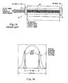
- a HeNe laser 14 with a cavity 16 having a length of 30 cm, as defined by the spacing between mirrors 18 and 20, has axial modes spaced at 500 MHz. Since the Doppler spectrum is typically only 1000 MHz in width for Neon (the lasing atom), only 2 axial modes can be present at any one time in a laser device of this length as indicated in FIGURE l(b).
- the laser When axial modes are present without the presence of off-axis transverse modes, the laser is said to be operating TEM . If only one axial mode is present, the laser is said to be operating single frequency.
- HeNe lasers Another characteristic of HeNe lasers is that the gain is very low ( ⁇ 1-5%), and thus the output extracted from the cavity is likewise only a small percentage of the resonating cavity energy density.
- intercavity use of such lasers have been developed. However, because of the low gain, intercavity losses introduced must likewise be small.
- One well developed intercavity use has been in the field of particle size measurements (other uses include measurements of extinction and refractivity of gases and reflectivity of optical surfaces.
- access to laser cavity 22 can be gained by terminating plasma tube 2 4 at one end with a Brewster's window 26.
- a photodetector 30 and preamplifier 32 are conventionally positioned along the laser beam axis outside mirror 28 to provide a measure of relative intensity of illumination.
- a sample block 38 is positioned above the particle injection area, and block 38 positions light collecting optical elements, such as a pair of lenses 40 and 41, above and close to the particle injection area.
- a scattering photodetector module 43 is positioned adjacent to block 38, and module 43 includes photodiode 45, conventionally located in the focal plane of lenses 40 and 41, and an amplifier 46.
- the output from scattering photodetector module 43 is coupled to readout 47 (which may be an oscilloscope, for example).
- readout 47 which may be an oscilloscope, for example.
- Photodetector 49 and preamplifier 50 may be optionally positioned along the laser beam axis at the other side of mirror 36 to provide the reference measurement as would photodector 30 and preamplifier 32 .
- Difficulties such as set forth hereinabove in, using open cavity resonant devices for sizing particles has resulted in attempts to use external cavities fed by standard lasers as indicated typically in FIGURE 3.
- a passive cavity 52 is established between external mirror 54 and output coupler mirror 56, while an active cavity 58 is established within tube 60 by mirror 56 at one end and mirror 62 at the opposite end.
- External mirror 54, output coupler mirror 56 and mirror 62 are beam shaping elements.
- External mirror 54 is of high reflectivity and this results in the retroreflection of the output power back toward output coupler 56.
- the energy builds up in the external (passive) cavity 52 to such a level that it feeds a certain percentage back into the active gain region 58 between mirrors 56 and 62. This can be observed by monitoring the leakage out of mirror 62 increasing as alignment of mirrors 54 and 56 is approached.
- the instabilities of arrangements render them undesirable as illumination devices for particle size or related measurements.
- the external . cavity is limited to Q values of 5 to 10, at best, due to the lack of exact phase locking and competition between the cavities having gain.
- the energy feedback is only exactly in phase at discrete spacings of mirrors 54 and 56, just as was the case of the above described open cavity laser device. These correspond to strong enhancements observed at mirror 62.
- Such an arrangement could be stable if operated single frequency and both cavities had precise half integral spacing with respect to the wavelength, or, if both cavities had exactly the same wavelength. Maintenance of such precise spacings, however, is virtually impossible.
- This invention stabilizes a passive cavity that is being fed by an active cavity (laser) regardless of cavity length.
- Q values of at least a hundred have easily been produced.
- the maximum Q value is limited solely by losses in the external cavity in the same manner as the active cavity. Normally, the Q value of the passive and active cavities will be nearly identical.
- Stabilization of the passive cavity is achieved by modulating external mirror 54 along the laser axis by use of suitable linear oscillation.
- the effect of movement of external mirror 54 is to sufficiently Doppler shift each reflected wave producing a new frequency that will not interfere with the stable axial modes of the active cavity. Subsequent reflections produce additional frequencies until a broad incoherent spectrum results in the passive cavity. An additional result is the destruction of gain within the third cavity defined by mirrors 54 and 62 (see FIGURE 4).
- FIGURE 4(a) illustrates an arrangment wherein sustained movement of external mirror 54 is effected by a common "woofer" audio speaker (voice coil) 66.
- mirror 54 is attached at the center of audio speaker 66 (mirrors 54 and 62 are high reflectivity mirrors ( ⁇ 0.1%) transmission) while mirror 56 is an output coupler mirror ( ⁇ 1%) transmission), and audio speaker 66 is oscillated by modulator 67.
- the translational velocity is the relevant parameter.
- a 4 inch voice coil can be driven by a 60Hz (common line AC) frequency at 2 to 3 volts (rms) to provide a few millimeters displacement. This correlates to the appropriate velocity range.
- sample block 81 is positioned above the particle injection area, and block 81 positions light collecting optical elements, such as a pair of lenses 83 and 84, above and close to the particle injection area.
- a scattering photodetector module 86 is positioned adjacent to block 81, and module 86 includes a photodiode 88 , conventionally located in the focal plane of lenses 83 and 84, and an amplifier 89. The output from scattering photodetector module 86 is coupled to readout 91 (which also may be an oscilloscope, for example).
- the laser is caused to generate the laser beam and the external mirror is caused to oscillate with the frequency and amplitude being adjusted to achieve passive cavity stabilization.
- the particles are then injected into the laser beam in the passive cavity as shown in FIGURES 4(a) and 4(c), and output readings are obtained at readout device 91. The fluctuations in such readings may then be utilized to provide size measurements as is known in the art.
- a laser device with stabilization of the passive caavity is particularly useful as an illumination device for particle size measurements and such use is nearly ideal.
- mirror 54 can also be an output coupler for coupling stabilized passive cavity energy from the device for use externally of the passive cavity.
- any laser can be used, even those with complex high-order multi-mode structures such as shown by the laser beam presentation and associated graphs of FIGURE 5.
- the passive cavity When the passive cavity is stabilized according to' this invention, the passive cavity exhibits (at mirror 54) little of the self-reproducing complex structure since the frequency and phase-shifting arising from modulation of external mirror 54 mixes many waves of differing frequency and phase content. This is shown by the laser beam presentation and associated graphs of FIGURE 6.
- a 5 mw multi-mode laser (30 cm cavity) was used to drive a passive cavity with a Q value of 200 producing an energy density of 1 watt.
- This passive cavity was used as a replacement for a conventional open cavity arrangement, and the same sensitivities were obtained with remarkable improvements in stability and reproducibility.
- the maximum Q value of the passive cavity is primarily limited by the quality of the anti-reflection (AR) coating on the transmitting face of the output coupler mirror 56. Mirrors can be fairly easily manufactured with losses of less than 0.01%, but anti-reflection coatings cannot. Furthermore, as previously mentioned, the passive cavity nominally has a Q similar to the active cavity. Consider an active cavity having a 99.99% reflectivity for mirror 62 and 99.81% reflectivity for mirror 56, its total transmission loss is 0.2% and its Q is thus 500 in the absence of additional unknown losses. The output feeds the external cavity which is defined by mirrors 54 and 56. If mirror 56 also has 99.99% reflectivity and the AR coating is perfect, then the passive cavity would also have a Q of 500. However, if the AR coating has 0.1% loss, then the external cavity would lose 0.4% for each round top reflection and lower the Q to 250.
- AR anti-reflection
- the beam width in the passive cavity can be tailored by constructing output coupler 56 so that the output is focused on mirror 54 or by appropriate choices of radii on the transmitting face.
- Use of a fairly short radius generates a short focus, and with mirror 54 positioned at the focus, the arrangement is very insensitive to alignment.
- the displacement of mirror 54 must, however, be small and therefore the modulating frequency increased to achieve sufficient desirable Doppler frequency shifting.
- modulation of the external mirror of an open cavity device also results in a filled Doppler envelope of frequencies and reduces annoying effects of exact - phase coherence and the resulting standing waves.
- this invention provides an improved laser device having a passive cavity stabilized by modulation of the external mirror.
Landscapes
- Physics & Mathematics (AREA)
- Electromagnetism (AREA)
- Engineering & Computer Science (AREA)
- Plasma & Fusion (AREA)
- Optics & Photonics (AREA)
- Lasers (AREA)
- Investigating Or Analysing Materials By Optical Means (AREA)
- Laser Surgery Devices (AREA)
- Optical Radar Systems And Details Thereof (AREA)
Priority Applications (1)
| Application Number | Priority Date | Filing Date | Title |
|---|---|---|---|
| AT84113707T ATE76704T1 (de) | 1983-11-17 | 1984-11-13 | Laser mit stabilisierter externer passiver kavitaet. |
Applications Claiming Priority (2)
| Application Number | Priority Date | Filing Date | Title |
|---|---|---|---|
| US06/552,689 US4594715A (en) | 1983-11-17 | 1983-11-17 | Laser with stabilized external passive cavity |
| US552689 | 1983-11-17 |
Publications (3)
| Publication Number | Publication Date |
|---|---|
| EP0142815A2 true EP0142815A2 (de) | 1985-05-29 |
| EP0142815A3 EP0142815A3 (en) | 1987-10-14 |
| EP0142815B1 EP0142815B1 (de) | 1992-05-27 |
Family
ID=24206377
Family Applications (1)
| Application Number | Title | Priority Date | Filing Date |
|---|---|---|---|
| EP84113707A Expired - Lifetime EP0142815B1 (de) | 1983-11-17 | 1984-11-13 | Laser mit stabilisierter externer passiver Kavität |
Country Status (6)
| Country | Link |
|---|---|
| US (1) | US4594715A (de) |
| EP (1) | EP0142815B1 (de) |
| JP (1) | JP2554614B2 (de) |
| AT (1) | ATE76704T1 (de) |
| CA (1) | CA1228148A (de) |
| DE (1) | DE3485749D1 (de) |
Cited By (1)
| Publication number | Priority date | Publication date | Assignee | Title |
|---|---|---|---|---|
| US10855047B1 (en) | 2018-11-06 | 2020-12-01 | United States Of America As Represented By The Secretary Of The Air Force | Passively cavity-dumped laser apparatus, system and methods |
Families Citing this family (43)
| Publication number | Priority date | Publication date | Assignee | Title |
|---|---|---|---|---|
| US4798465B2 (en) * | 1986-04-14 | 1994-08-30 | Particle Measuring Syst | Particle size detection device having high sensitivity in high molecular scattering environment |
| DE3930642C2 (de) * | 1988-09-13 | 1999-09-23 | Particle Measuring Syst | Hochempfindlicher Teilchengrößendetektor mit Rauschunterdrückung |
| US5135304A (en) * | 1990-05-11 | 1992-08-04 | Boc Health Care, Inc. | Gas analysis system having buffer gas inputs to protect associated optical elements |
| US5153671A (en) * | 1990-05-11 | 1992-10-06 | Boc Health Care, Inc. | Gas analysis system having buffer gas inputs to protect associated optical elements |
| US5245405A (en) * | 1990-05-11 | 1993-09-14 | Boc Health Care, Inc. | Constant pressure gas cell |
| JP3564705B2 (ja) * | 1992-03-02 | 2004-09-15 | ソニー株式会社 | レーザ光発生装置 |
| US5315603A (en) * | 1993-01-11 | 1994-05-24 | The United States Of America As Represented By The Secretary Of The Air Force | Backscatter absorption for laser diodes |
| US5751422A (en) * | 1996-02-26 | 1998-05-12 | Particle Measuring Systems, Inc. | In-situ particle detection utilizing optical coupling |
| US5726753A (en) * | 1996-02-26 | 1998-03-10 | Research Electro-Optics, Inc. | Intracavity particle detection using optically pumped laser media |
| US5642193A (en) * | 1996-03-08 | 1997-06-24 | Met One, Inc. | Particle counter employing a solid-state laser with an intracavity view volume |
| US5920388A (en) * | 1996-10-15 | 1999-07-06 | Research Electro-Optics, Inc. | Small particle characteristic determination |
| US5946092A (en) * | 1998-02-27 | 1999-08-31 | Pacific Scientific Instruments Company | Dual laser heterodyne optical particle detection technique |
| US7796255B2 (en) * | 2007-03-23 | 2010-09-14 | Particle Measuring Systems, Inc. | Optical particle sensor with exhaust-cooled optical source |
| CN101910821B (zh) | 2007-12-04 | 2012-09-05 | 粒子监测系统有限公司 | 非正交粒子检测系统和方法 |
| US8800383B2 (en) | 2009-08-24 | 2014-08-12 | Particle Measuring Systems, Inc. | Flow monitored particle sensor |
| KR102104987B1 (ko) | 2011-12-01 | 2020-04-28 | 파티클 머슈어링 시스템즈, 인크. | 입자 크기 및 농도 측정을 위한 검출 스킴 |
| US12044611B2 (en) | 2013-03-15 | 2024-07-23 | Particles Plus, Inc. | Particle counter with integrated bootloader |
| US10983040B2 (en) | 2013-03-15 | 2021-04-20 | Particles Plus, Inc. | Particle counter with integrated bootloader |
| US11579072B2 (en) | 2013-03-15 | 2023-02-14 | Particles Plus, Inc. | Personal air quality monitoring system |
| US9677990B2 (en) | 2014-04-30 | 2017-06-13 | Particles Plus, Inc. | Particle counter with advanced features |
| US10352844B2 (en) | 2013-03-15 | 2019-07-16 | Particles Plus, Inc. | Multiple particle sensors in a particle counter |
| ITRM20130128U1 (it) | 2013-07-23 | 2015-01-24 | Particle Measuring Systems S R L | Dispositivo per il campionamento microbico dell'aria |
| WO2015148148A1 (en) | 2014-03-14 | 2015-10-01 | Particle Measuring Systems, Inc. | Pressure-based airflow sensing in particle impactor systems |
| US9631222B2 (en) | 2014-03-14 | 2017-04-25 | Particle Measuring Systems, Inc. | Filter and blower geometry for particle sampler |
| KR102601473B1 (ko) | 2017-10-26 | 2023-11-10 | 파티클 머슈어링 시스템즈, 인크. | 입자 측정을 위한 시스템 및 방법 |
| JP2021535999A (ja) | 2018-08-31 | 2021-12-23 | パーティクル・メージャーリング・システムズ・インコーポレーテッド | 流体屈折率最適化粒子計数器 |
| JP7504866B2 (ja) | 2018-09-04 | 2024-06-24 | パーティクル・メージャーリング・システムズ・インコーポレーテッド | 生産機器および表面上のナノ粒子の検出 |
| US11385161B2 (en) | 2018-11-12 | 2022-07-12 | Particle Measuring Systems, Inc. | Calibration verification for optical particle analyzers |
| WO2020102038A1 (en) | 2018-11-12 | 2020-05-22 | Particle Measuring Systems, Inc. | Calibration verification for optical particle analyzers |
| KR102779340B1 (ko) | 2018-11-16 | 2025-03-07 | 파티클 머슈어링 시스템즈, 인크. | 슬러리 모니터 커플링 벌크 크기 분포 및 단일 입자 검출 |
| KR102880992B1 (ko) | 2018-11-16 | 2025-11-03 | 파티클 머슈어링 시스템즈, 인크. | 로봇 제어된 제조 장벽 시스템을 위한 입자 샘플링 시스템 및 방법 |
| US11237095B2 (en) | 2019-04-25 | 2022-02-01 | Particle Measuring Systems, Inc. | Particle detection systems and methods for on-axis particle detection and/or differential detection |
| WO2021071793A1 (en) | 2019-10-07 | 2021-04-15 | Particle Measuring Systems, Inc. | Antimicrobial particle detectors |
| JP7520961B2 (ja) | 2019-10-07 | 2024-07-23 | パーティクル・メージャーリング・システムズ・インコーポレーテッド | 遠隔警報監視及び制御を有する粒子検出器 |
| IT201900020248A1 (it) | 2019-11-04 | 2021-05-04 | Particle Measuring Systems S R L | Dispositivo di monitoraggio mobile per aree a contaminazione controllata |
| EP4062146A4 (de) | 2019-11-22 | 2024-02-28 | Particle Measuring Systems, Inc. | Fortgeschrittene systeme und verfahren zur interferometrischen teilchendetektion und detektion von teilchen mit kleinen abmessungen |
| TWI829492B (zh) | 2020-01-21 | 2024-01-11 | 美商粒子監測系統有限公司 | 撞擊器及用於對來自一流體流之生物顆粒取樣之方法 |
| US11988591B2 (en) | 2020-07-01 | 2024-05-21 | Particles Plus, Inc. | Modular optical particle counter sensor and apparatus |
| EP4356053A4 (de) | 2021-06-15 | 2025-05-28 | Particle Measuring Systems, Inc. | Kondensationspartikelzähler und verfahren zur verwendung |
| WO2022266052A1 (en) | 2021-06-15 | 2022-12-22 | Particle Measuring Systems, Inc. | Modular particle counter with docking station |
| EP4356099A4 (de) | 2021-06-15 | 2025-06-18 | Particle Measuring Systems, Inc. | Kompakter intelligenter aerosol- und flüssigkeitsverteiler |
| WO2023141488A2 (en) | 2022-01-21 | 2023-07-27 | Particle Measuring Systems, Inc. | Enhanced dual-pass and multi-pass particle detection |
| US12461010B2 (en) | 2023-11-16 | 2025-11-04 | Particle Measuring Systems, Inc. | Systems and methods for reducing false positive particle detection events in a particle detector |
Family Cites Families (9)
| Publication number | Priority date | Publication date | Assignee | Title |
|---|---|---|---|---|
| US3406289A (en) * | 1965-11-10 | 1968-10-15 | Univ Iowa State Res Found Inc | Laser small-particle detector and method |
| US3534289A (en) * | 1967-02-06 | 1970-10-13 | Xerox Corp | Laser system with optical discriminator |
| US3718868A (en) * | 1970-07-20 | 1973-02-27 | Univ Case Western Reserve | I{11 {11 {11 {11 INVERTED LAMB DIP STABILIZED He-Ne LASER |
| BE789352A (fr) * | 1971-09-27 | 1973-01-15 | Siemens Ag | Procede pour la stabilisation de la frequence d'un laser |
| US3833308A (en) * | 1973-08-01 | 1974-09-03 | Mead Corp | Binder fixture |
| JPS5229912A (en) * | 1975-09-03 | 1977-03-07 | Hitachi Ltd | Slipping detection system for induction motor |
| JPS5837712B2 (ja) * | 1975-09-23 | 1983-08-18 | 三洋電機株式会社 | キタイレ−ザソウチ |
| JPS5424277A (en) * | 1977-07-26 | 1979-02-23 | Mitsubishi Heavy Ind Ltd | Wet desulfurizing method for exhaust combustion gas |
| GB2057181B (en) * | 1979-08-16 | 1983-08-24 | Plessey Co Ltd | Gas laser arrangements |
-
1983
- 1983-11-17 US US06/552,689 patent/US4594715A/en not_active Expired - Lifetime
-
1984
- 1984-11-13 JP JP59237708A patent/JP2554614B2/ja not_active Expired - Fee Related
- 1984-11-13 AT AT84113707T patent/ATE76704T1/de not_active IP Right Cessation
- 1984-11-13 EP EP84113707A patent/EP0142815B1/de not_active Expired - Lifetime
- 1984-11-13 DE DE8484113707T patent/DE3485749D1/de not_active Expired - Lifetime
- 1984-11-16 CA CA000467983A patent/CA1228148A/en not_active Expired
Cited By (1)
| Publication number | Priority date | Publication date | Assignee | Title |
|---|---|---|---|---|
| US10855047B1 (en) | 2018-11-06 | 2020-12-01 | United States Of America As Represented By The Secretary Of The Air Force | Passively cavity-dumped laser apparatus, system and methods |
Also Published As
| Publication number | Publication date |
|---|---|
| EP0142815B1 (de) | 1992-05-27 |
| EP0142815A3 (en) | 1987-10-14 |
| JP2554614B2 (ja) | 1996-11-13 |
| DE3485749D1 (de) | 1992-07-02 |
| CA1228148A (en) | 1987-10-13 |
| JPS60160190A (ja) | 1985-08-21 |
| US4594715A (en) | 1986-06-10 |
| ATE76704T1 (de) | 1992-06-15 |
Similar Documents
| Publication | Publication Date | Title |
|---|---|---|
| EP0142815B1 (de) | Laser mit stabilisierter externer passiver Kavität | |
| US11131626B2 (en) | Optical absorption spectroscopy based gas analyzer systems and methods | |
| Stewart et al. | An investigation of an optical fibre amplifier loop for intra-cavity and ring-down cavity loss measurements | |
| US8659759B2 (en) | Laser based cavity enhanced optical absorption gas analyzer | |
| CN113008829B (zh) | 一种基于光学反馈的近红外线性腔增强吸收光谱装置 | |
| CN118483178B (zh) | 一种获得脉冲里德堡原子光谱的装置和方法 | |
| CN112098737A (zh) | 一种微波电场强度的测量方法及装置 | |
| JPH10300853A (ja) | コヒーレント検出を使用するレーザ速度計および測距計 | |
| CN115825592B (zh) | 基于量子传感的电场精密测量新型分布式系统 | |
| CN117368148A (zh) | 时间分辨腔衰荡光谱测量装置 | |
| JPH0732294B2 (ja) | コヒ−レント放射発生方法および装置 | |
| JPH07270308A (ja) | 光学式ガス分析装置 | |
| US4156571A (en) | Laser mirror scatter and reflectivity measuring system | |
| CN116256675A (zh) | 一种基于激光光源的光泵磁强计 | |
| US4208129A (en) | Sensitive laser spectroscopy measurement system | |
| CN117452084A (zh) | 基于光纤相位调制器和光学超稳腔线性扫频的装置 | |
| US3644841A (en) | Frequency-stabilized single mode ring lasers | |
| JP3165956B2 (ja) | 微粒子測定装置 | |
| RU2054773C1 (ru) | Частотно-стабилизированный лазер | |
| JP4589620B2 (ja) | 光波長基準装置 | |
| JPH10246694A (ja) | ガスセンサ及びそれを用いた気体検出方法 | |
| Yan et al. | Frequency stabilization of a CO2 laser using Lamb-dip from a photo-acoustic cell | |
| Cheon et al. | Design of a far-infrared interferometer/polarimeter system for Korea Superconducting Tokamak Advanced Research | |
| US6574252B1 (en) | Radio frequency excited slab waveguide laser comprising detector and method of stabilizing the laser power and frequency using optogalvanic effect | |
| JPH0549055B2 (de) |
Legal Events
| Date | Code | Title | Description |
|---|---|---|---|
| PUAI | Public reference made under article 153(3) epc to a published international application that has entered the european phase |
Free format text: ORIGINAL CODE: 0009012 |
|
| AK | Designated contracting states |
Designated state(s): AT BE CH DE FR GB IT LI LU NL SE |
|
| PUAL | Search report despatched |
Free format text: ORIGINAL CODE: 0009013 |
|
| AK | Designated contracting states |
Kind code of ref document: A3 Designated state(s): AT BE CH DE FR GB IT LI LU NL SE |
|
| 17P | Request for examination filed |
Effective date: 19880412 |
|
| 17Q | First examination report despatched |
Effective date: 19900123 |
|
| GRAA | (expected) grant |
Free format text: ORIGINAL CODE: 0009210 |
|
| AK | Designated contracting states |
Kind code of ref document: B1 Designated state(s): AT BE CH DE FR GB IT LI LU NL SE |
|
| PG25 | Lapsed in a contracting state [announced via postgrant information from national office to epo] |
Ref country code: SE Free format text: THE PATENT HAS BEEN ANNULLED BY A DECISION OF A NATIONAL AUTHORITY Effective date: 19920527 Ref country code: NL Effective date: 19920527 Ref country code: LI Effective date: 19920527 Ref country code: IT Free format text: LAPSE BECAUSE OF FAILURE TO SUBMIT A TRANSLATION OF THE DESCRIPTION OR TO PAY THE FEE WITHIN THE PRESCRIBED TIME-LIMIT;WARNING: LAPSES OF ITALIAN PATENTS WITH EFFECTIVE DATE BEFORE 2007 MAY HAVE OCCURRED AT ANY TIME BEFORE 2007. THE CORRECT EFFECTIVE DATE MAY BE DIFFERENT FROM THE ONE RECORDED. Effective date: 19920527 Ref country code: FR Effective date: 19920527 Ref country code: CH Effective date: 19920527 Ref country code: BE Effective date: 19920527 Ref country code: AT Effective date: 19920527 |
|
| REF | Corresponds to: |
Ref document number: 76704 Country of ref document: AT Date of ref document: 19920615 Kind code of ref document: T |
|
| REF | Corresponds to: |
Ref document number: 3485749 Country of ref document: DE Date of ref document: 19920702 |
|
| REG | Reference to a national code |
Ref country code: CH Ref legal event code: PL |
|
| EN | Fr: translation not filed | ||
| NLV1 | Nl: lapsed or annulled due to failure to fulfill the requirements of art. 29p and 29m of the patents act | ||
| PG25 | Lapsed in a contracting state [announced via postgrant information from national office to epo] |
Ref country code: LU Free format text: LAPSE BECAUSE OF NON-PAYMENT OF DUE FEES Effective date: 19921130 |
|
| PLBE | No opposition filed within time limit |
Free format text: ORIGINAL CODE: 0009261 |
|
| STAA | Information on the status of an ep patent application or granted ep patent |
Free format text: STATUS: NO OPPOSITION FILED WITHIN TIME LIMIT |
|
| 26N | No opposition filed | ||
| REG | Reference to a national code |
Ref country code: GB Ref legal event code: IF02 |
|
| PGFP | Annual fee paid to national office [announced via postgrant information from national office to epo] |
Ref country code: GB Payment date: 20021007 Year of fee payment: 19 |
|
| PGFP | Annual fee paid to national office [announced via postgrant information from national office to epo] |
Ref country code: DE Payment date: 20021025 Year of fee payment: 19 |
|
| PG25 | Lapsed in a contracting state [announced via postgrant information from national office to epo] |
Ref country code: GB Free format text: LAPSE BECAUSE OF NON-PAYMENT OF DUE FEES Effective date: 20031113 |
|
| PG25 | Lapsed in a contracting state [announced via postgrant information from national office to epo] |
Ref country code: DE Free format text: LAPSE BECAUSE OF NON-PAYMENT OF DUE FEES Effective date: 20040602 |
|
| GBPC | Gb: european patent ceased through non-payment of renewal fee |
Effective date: 20031113 |