EP0142843A2 - Elément de support pour échafaudage suspendu - Google Patents
Elément de support pour échafaudage suspendu Download PDFInfo
- Publication number
- EP0142843A2 EP0142843A2 EP84113924A EP84113924A EP0142843A2 EP 0142843 A2 EP0142843 A2 EP 0142843A2 EP 84113924 A EP84113924 A EP 84113924A EP 84113924 A EP84113924 A EP 84113924A EP 0142843 A2 EP0142843 A2 EP 0142843A2
- Authority
- EP
- European Patent Office
- Prior art keywords
- support
- hook
- scaffolding
- parts
- vertical
- Prior art date
- Legal status (The legal status is an assumption and is not a legal conclusion. Google has not performed a legal analysis and makes no representation as to the accuracy of the status listed.)
- Withdrawn
Links
Images
Classifications
-
- E—FIXED CONSTRUCTIONS
- E04—BUILDING
- E04G—SCAFFOLDING; FORMS; SHUTTERING; BUILDING IMPLEMENTS OR AIDS, OR THEIR USE; HANDLING BUILDING MATERIALS ON THE SITE; REPAIRING, BREAKING-UP OR OTHER WORK ON EXISTING BUILDINGS
- E04G3/00—Scaffolds essentially supported by building constructions, e.g. adjustable in height
- E04G3/28—Mobile scaffolds; Scaffolds with mobile platforms
- E04G3/30—Mobile scaffolds; Scaffolds with mobile platforms suspended by flexible supporting elements, e.g. cables
-
- E—FIXED CONSTRUCTIONS
- E04—BUILDING
- E04G—SCAFFOLDING; FORMS; SHUTTERING; BUILDING IMPLEMENTS OR AIDS, OR THEIR USE; HANDLING BUILDING MATERIALS ON THE SITE; REPAIRING, BREAKING-UP OR OTHER WORK ON EXISTING BUILDINGS
- E04G3/00—Scaffolds essentially supported by building constructions, e.g. adjustable in height
- E04G3/22—Scaffolds essentially supported by building constructions, e.g. adjustable in height supported by roofs or ceilings
Definitions
- the invention relates to a support element for hanging scaffolding for lifting, lowering and in the position of use holding scaffolding parts and / or work platforms with a traction device and with an adjoining hook-shaped supporting part for hanging, inserting and supporting scaffolding parts.
- Suspended scaffolds are suspended structures for supporting and erecting mostly temporarily used work platforms or work platforms.
- Such suspended scaffolds are required above all when working near covered supporting structures, such as under roofs, under bridges, but also in chemical plants and when working on ship hulls or other work in which a work platform has to be suspended from above.
- Such work platforms generally have floor parts on which the users can stand, walk and put down their equipment. These floor parts are covering boards or wooden planks. They are supported by a support system that is connected to the suspension structure, which in turn is supported by the support systems located above.
- Such support systems can be the beams or beams of a permanent construction, such as a roof or the like.
- the working platforms mentioned here are used a lot, especially in the petrochemical industry, especially for laying on, maneuvering, aligning, isolating and / or painting, connecting and connecting pipelines etc. via I-beams.
- the hanging scaffolds are usually made entirely of scaffolding material, which is also used for erection or side installation. Scaffold tubes, lattice girders, couplings, special hooks and the other usual scaffolding materials are usually used for such suspended scaffolding.
- horizontal scaffold tubes can be guided over the supports of the building or the like to which the work platform to be used temporarily is to be attached.
- the supporting element of the hanging structure is essentially constructed in three parts, namely on the one hand with a supporting part, which allows support compared to other supporting structures, on the other hand a movable and height-adjustable traction means and, on the other hand, a hook-shaped supporting part, which allows the scaffolding parts to be connected.
- a group of inventions are to be treated which are interlinked in such a way that they implement a single general inventive idea, the one therein consists of designing the means of attack for the scaffolding parts and the supporting structure in hanging scaffolding of the type mentioned in such a way that they do justice to the most varied of applications and scaffolding part combinations and supports.
- special attention must be paid to the hook and, despite being suspended on a movable traction device, such as a chain or a rope, the horizontal and vertical alignment of the connected parts must always be possible without pivoting.
- the lower support area of the hook-shaped support part of the hook has symmetrically stepped support and contact surfaces with respect to the center line passing through the suspension for supporting as thickly as possible without side and torsional forces.
- This makes it possible to support the scaffold part, for example a scaffold tube or a lattice girder with tubular upper and lower chords, on the center line, as well as a thicker beam or two folded planks.
- the gradation can be formed by corner pieces running symmetrically to the center line and equipped with vertical and horizontal support and contact surfaces, which preferably consist of angle or hollow tube parts. So you can easily implement the desired gradation with distance and height dimensions that correspond to the standard scaffolding parts in a square receiving area of the hook that is also to be dealt with further below.
- the hook-shaped support part is designed as a hook which has vertically and / or horizontally running hollow areas or tubes which have at least one end opening.
- Scaffold tubes, scaffold tube parts or other profile parts can then be inserted or pushed through into such hollow areas or pipes, thereby holding the hook in the desired position on the one hand, even if lateral forces or torsional forces occur, and on the other hand can be quickly installed and, for example, create supports for the covering panels or back protection or form railings directly or insert railing rods.
- Such hollow areas are. Appropriately intended for horizontal and vertical insertion, and their dimensions are chosen so that the inside diameter of the hollow areas or tubes correspond to the outside diameter of standardized or standardized scaffolding tubes, for example inside dimensions of about 50 mm.
- a hollow area can consist of a continuous, preferably open on both sides, horizontal tube piece directly below the fastening part for the traction means.
- a scaffold tube can then be pushed through the horizontal hollow areas of two hooks, thereby preventing their mutual rotation. It can be used to support covering panels or directly as back protection or railing.
- a further hollow area can be formed by a vertical tube piece that delimits the preferably stepped receiving space on one side and is open at the top and vertical in the position of use.
- Such an open hollow area allows rods to be inserted for connecting railings or back guards.
- vertically inserted pipes or stems can also be used to connect other scaffolding parts, for example with step scaffolding.
- a hook of a suspended scaffold designed in accordance with the invention can then furthermore have a vertical connecting part between the upper horizontal pipe piece and the lower support area, which runs at the same distance from the center line as the vertical pipe piece open at the top and is longer than the vertical pipe piece by the insertion opening of the hook. In this way, the receiving space is automatically formed between the two vertical parts and is to be designed accordingly.
- the hook also otherwise consists of hollow parts, it is expedient to also make the vertical connecting part hollow and to form a side opening in its upper region, the diameter of which is at least the outer dimensions of the largest chain link or the rope end of the traction means. Then you can insert the respective end of the traction device into the cavity of the hook and keep it there so that it does not interfere with use.
- the tubes can be round tubes, however, due to the formation of the contact surfaces and the like, square tubes are expediently used:
- a hanging scaffold with hooks of the type described above can be attached to a wide variety of supports with the traction device depending on the application. Since such suspended scaffolding is often immediate hanging under roof structures with double-T beams, which are also referred to simply as 'I beams' below, it is advisable to assign a beam clamp to it.
- a beam clamp of this type which is expediently designed as part of the overall task of rationally assembling suspended scaffolding in different applications, provides according to the invention that the beam clamp is formed with articulated clamp arms which have contact surfaces for the lower flanges of preferably I-shaped beams and wherein the clamp arms are connected by a bolt which limits the maximum opening movement and is lockable in the position of use, and in that a longitudinally extending alignment part is provided on at least one of the clamp arms in the region of the support surfaces.
- Such a carrier clamp can simply be opened, placed around the lower flange and then closed. The locking ensures a secure hold and the alignment part ensures that the beam clamp is not rotated and thus both flanges are loaded evenly and the beam clamp cannot slip off.
- the bolt or its engaging elements can be designed so that it has locking means.
- a beam clamp can be attached much more easily from below while standing on a ladder than a scaffold part construction.
- it is of great advantage if the worker sits on the I-beam running at a great height and, if necessary, pulls the support element up together with other connected parts and then has to fasten it to the lower flange in the sitting position. It is particularly important to ensure a lock that automatically locks into the position of use.
- the distance between the alignment parts and the design of the bracket arm corners in the lower area must be such that the thickest web of the I-beam that occurs in a certain size range can be accommodated in between without the contact surface reaching the corner rounding.
- a simple and safe-functioning design for a locking device that takes this thickness range into account can be used.
- a lock with an L-shaped slot is particularly suitable for such a lock, which engages automatically, and a pin serving as a locking pin enters the short leg of the lock when it reaches the position of use due to the dead weight of the lock.
- the device is simple, easy to see from the outside, whether it has reached its resting position and easy to open when dismantling.
- Such a carrier clamp can also be combined with other connection means for scaffolding and scaffolding parts.
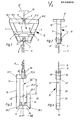
- the support element of a suspended scaffold shown in FIGS. 1 to 4 consists of a support clamp 15, a traction means in the form of a chain 8 and the hook 10, which can be used together and also individually and can be connected to one another by the chain at different distances.
- the carrier clamp forming the upper part consists of two clamp arms 1 originally referred to as main lower parts, which are connected in their lower region to a joint 2.
- a bolt 3 limits the possibilities of movement of the clamp arms 1 with one another in such a way that it permits an open state and a working state.
- the bolt 3 is articulated with a joint 4 on the left bracket arm 1 during the right clamp arm 1 has a pin 14 which engages through an L-shaped slot 5 in the bolt 3, the L-shaped slot being placed so that the bolt 3 falls into its locked position by its own weight in the working state shown, so that the Bracket arms 1 are mutually secured.
- the clamp arms 1 have upper support arms 16.1 and 16.2, which form the support surfaces 17.1 and 17.2, with which they rest on the flange 18 of an I-beam 20, for example a roof structure, under which the suspended scaffold is to be hung. They have the web 19 of the I-beam 20 between their ends. To rest against the web 19, both support arms 16 have alignment parts 6 at their ends, which are welded in the form of angle profiles to their upper regions, for example, and - as in FIG. 1 can be seen - on the web 19 of the I-beam 20 in the use position of the clamp arms lie so snugly that the clamp can neither be shifted laterally in the plane of FIG. 1 nor pivoted about its supports, so that they are certainly the ones intended for them Introduces forces evenly into the flange 18.
- the alignment parts 6 have the function of restricting the possibility of angular rotation with regard to the position of the I-beam.
- a ring 7 is attached to the joint 2.
- the traction device here in the form of the chain 8 is attached to it with a normal shackle.
- a chain link is hung in the corresponding position in the special chain hook 9, which is also on the ring 7 is attached.
- FIGS. 3 and 4 show the hook 10.
- this essentially consists of a plurality of square tube pieces welded together, namely an upper horizontal tube piece 22, a vertical connecting part 23, a support tube 24 and a vertical tube piece 25 attached a round piece of pipe 11, which serves as a loop bearing for the chain 8.
- the two end faces 22.1 and 22.2 of the horizontal tube piece 22 are open.
- the horizontal tube piece 22 has inner edge lengths of the profile of about 50 mm, so that a conventional scaffold tube of 48.3 mm outer diameter can be pushed through the horizontal tube piece 22 easily. For example, it can be pushed together with its pipe pieces 22 by two mutually facing hooks, so that the hooks are also prevented from rotating.
- the vertical pipe section 25 delimits the receiving space 27 on the right side in FIG. 3. It is connected to the support tube 24 in the lower corner according to the miter line 28, for example welded. Its upper end face 25.1 is open. Since the vertical tube piece 25 also has an inner edge length of the profile of approximately 50 mm, a scaffold tube of, for example, 48.3 mm diameter can be inserted comfortably.
- the inner contact line 25.2 is indicated and it can be seen that the horizontal pipe section 22 only extends up to this contact line 25.2, so that a scaffold tube can also be inserted of greater length.
- the vertical connecting part 23 is connected in the miter line 28.2 to the support pipe piece 24 and welded in the upper area under the horizontal pipe piece 22.
- the vertical connecting part 23 also consists of a hollow square tube. In its upper area it has a side opening 13, which was originally called a hole. Their diameter is such that the largest chain link or rope end with its corresponding reinforcements can be pushed through, so that the unused part of the chain or rope is housed in the vertical tube piece 23 for storage during use.
- the receiving space 27 is formed between the vertical pipe sections 23 and 25. Through this goes from the center of the round pipe section 11 center line M. The arrangement is such that both pipe sections 23 and 25 are at the same distance from the center line, so that appropriately inserted bars or double planks are supported in the middle.
- the length of the vertical connecting part 23 is made taking into account the length of the vertical pipe section 25 so that an insertion opening 29 remains at the distance E.
- the vertical pipe section 25 is selected to be long enough to ensure good lateral support in the receiving space 27 for beams or planks.
- the distance E corresponds to the largest part of the scaffold to be inserted laterally.
- Corner pieces 12 are provided so that thinner parts can also be inserted centrally. These are welded into the corners as angular parts or pipe parts and have horizontal contact surfaces and vertical contact surfaces. They are arranged symmetrically to the center line M, so that there is a narrower central receiving space 27.1, which is dimensioned such that a conventional scaffold tube or the tube of a lattice girder can be inserted centrally. Such Pipes or lattice girders can then connect at least two hooks accordingly and be supported on them so that the platforms can be formed with covering panels and / or planks. Each part to be inserted is therefore symmetrical with respect to the center line M, so that this line runs vertically or almost vertically when the hook is loaded, regardless of whether wider bars or parts or narrower ones are inserted.
- the hook can also be formed with round tubes or can be formed in a suitable molding process to create the cavities. It allows the diverse insertion, placement and fastening of scaffolding parts for hanging scaffolding.
- a scaffold pre-assembled on the ground with the aid of several such hooks can be raised to the desired height and secured by hooking the chain into the hook 9.
- the connection options on the hook are advantageously in almost the same working position. For example, if a worker sits on an I-beam, he can first easily clamp the beam clamp securely after pulling up the corresponding parts and then insert the further supporting parts, such as pipes, lattice beams or planks, from the side into the insertion opening 29 without his working position to have to leave.
- the carrier clamp and the design of the hook because both together are advantageous for the many applications in chemical plants and it is also possible to insert vertical or horizontal pipe sections or profile parts in the hook without a significant change in assembly space.
Landscapes
- Engineering & Computer Science (AREA)
- Architecture (AREA)
- Mechanical Engineering (AREA)
- Civil Engineering (AREA)
- Structural Engineering (AREA)
- Movable Scaffolding (AREA)
- Control Of Vending Devices And Auxiliary Devices For Vending Devices (AREA)
- Measurement Of The Respiration, Hearing Ability, Form, And Blood Characteristics Of Living Organisms (AREA)
- Toys (AREA)
Applications Claiming Priority (2)
| Application Number | Priority Date | Filing Date | Title |
|---|---|---|---|
| NL8303998 | 1983-11-21 | ||
| NL8303998A NL8303998A (nl) | 1983-11-21 | 1983-11-21 | Hangconstructie. |
Publications (2)
| Publication Number | Publication Date |
|---|---|
| EP0142843A2 true EP0142843A2 (fr) | 1985-05-29 |
| EP0142843A3 EP0142843A3 (fr) | 1987-03-04 |
Family
ID=19842747
Family Applications (1)
| Application Number | Title | Priority Date | Filing Date |
|---|---|---|---|
| EP84113924A Withdrawn EP0142843A3 (fr) | 1983-11-21 | 1984-11-17 | Elément de support pour échafaudage suspendu |
Country Status (5)
| Country | Link |
|---|---|
| EP (1) | EP0142843A3 (fr) |
| DE (1) | DE8433755U1 (fr) |
| DK (1) | DK549084A (fr) |
| NL (1) | NL8303998A (fr) |
| NO (1) | NO844607L (fr) |
Family Cites Families (7)
| Publication number | Priority date | Publication date | Assignee | Title |
|---|---|---|---|---|
| US1577617A (en) * | 1925-09-25 | 1926-03-23 | Nat Mfg Co | Scaffold hoist |
| FR1116397A (fr) * | 1954-12-23 | 1956-05-07 | Pantz Ernest Ets | Perfectionnements aux échafaudages pour constructions |
| BE545561A (fr) * | 1955-03-04 | |||
| US2926880A (en) * | 1955-06-22 | 1960-03-01 | John B Bourgeois | Scaffolding supports |
| DE1965404U (de) * | 1967-02-23 | 1967-08-03 | Fritz Wilms | Haengegeruest od. dgl. |
| US3767010A (en) * | 1972-06-20 | 1973-10-23 | J Newlan | Scaffold device |
| US3945462A (en) * | 1975-06-18 | 1976-03-23 | Griswold James D | Hanger brackets |
-
1983
- 1983-11-21 NL NL8303998A patent/NL8303998A/nl not_active Application Discontinuation
-
1984
- 1984-11-17 EP EP84113924A patent/EP0142843A3/fr not_active Withdrawn
- 1984-11-17 DE DE19848433755 patent/DE8433755U1/de not_active Expired
- 1984-11-20 DK DK549084A patent/DK549084A/da unknown
- 1984-11-20 NO NO844607A patent/NO844607L/no unknown
Also Published As
| Publication number | Publication date |
|---|---|
| DK549084D0 (da) | 1984-11-20 |
| NL8303998A (nl) | 1985-06-17 |
| DK549084A (da) | 1985-05-22 |
| EP0142843A3 (fr) | 1987-03-04 |
| NO844607L (no) | 1985-05-22 |
| DE8433755U1 (de) | 1985-05-30 |
Similar Documents
| Publication | Publication Date | Title |
|---|---|---|
| EP3721028B1 (fr) | Équipement comprenant un dispositif anti-soulèvement et procédé pour empêcher un plancher d'échafaudage de se soulever | |
| DE2814930C2 (de) | Klettergerüst | |
| DE2704398A1 (de) | Keilverbindung | |
| EP2253764A2 (fr) | Treillis en forme de cadre | |
| EP4538481A1 (fr) | Dispositif pour la fixation de protections contre les chutes à des échafaudages | |
| DE2050516A1 (de) | Senkrecht verstellbare Plattform fur Baugerüste | |
| DE2217584C3 (de) | Kletterschalung für eine Betonwandschalung | |
| DE3200939A1 (de) | Deckentische zum giessen von betondecken | |
| CH657888A5 (de) | Metallgeruest mit zur sicherung dienenden, eine drahtgeflechtbespannung aufweisenden metallrahmen. | |
| DE820963C (de) | Baugeruest mit aus Rohren bestehenden Staendern | |
| DE9110828U1 (de) | Gerüst | |
| DE3341031A1 (de) | Geruestkonsole zum herstellen eines an den zur dachkonstruktion gehoerenden sparren, pfetten, riegel usw. befestigten in der hoehe u. breite verstellbaren konsolengeruestes | |
| DE3502659C2 (fr) | ||
| EP0142843A2 (fr) | Elément de support pour échafaudage suspendu | |
| EP1845215B1 (fr) | Poutre profilée en U pour toiture, tribune, escalier, échafaudage ou podium | |
| EP0736648A1 (fr) | Echafaudage | |
| DE4219732C2 (de) | Montagegerüst | |
| DE888161C (de) | Aus einzelnen vorher gefertigten Rahmen gebildetes Rohrbaugeruest | |
| DE3616838A1 (de) | Auf baustellen verwendbare vorrichtung zum anbringen von gelaenderbrettern od. dgl. | |
| EP0165946A1 (fr) | Dispositif porteur pour echafaudage | |
| DE102022114668B4 (de) | Bewehrungsvorrichtung | |
| EP3839172B1 (fr) | Longeron garde-corps destiné au montage d'un garde-corps avant, garde-corps avant destiné à la protection temporaire contre les chutes d'un nouvel étage d'un échafaudage à créer, échafaudage pour travaux de construction, de réparation et/ou de montage et processus de construction d'un échafaudage | |
| DE9110251U1 (de) | Gerüst | |
| DE1918773C3 (de) | Aus Bauteilen zusammensetzbare, aufhängbare und in Abschnitten verlängerbare Arbeltsbühne | |
| DE202023104730U1 (de) | Gerüstsystem zur Errichtung einer weiteren Gerüstetage mit vorlaufender Absturzsicherung |
Legal Events
| Date | Code | Title | Description |
|---|---|---|---|
| PUAI | Public reference made under article 153(3) epc to a published international application that has entered the european phase |
Free format text: ORIGINAL CODE: 0009012 |
|
| AK | Designated contracting states |
Designated state(s): AT BE CH DE FR GB IT LI LU NL SE |
|
| PUAL | Search report despatched |
Free format text: ORIGINAL CODE: 0009013 |
|
| AK | Designated contracting states |
Kind code of ref document: A3 Designated state(s): AT BE CH DE FR GB IT LI LU NL SE |
|
| STAA | Information on the status of an ep patent application or granted ep patent |
Free format text: STATUS: THE APPLICATION IS DEEMED TO BE WITHDRAWN |
|
| 18D | Application deemed to be withdrawn |
Effective date: 19870905 |
|
| RIN1 | Information on inventor provided before grant (corrected) |
Inventor name: BOELHOUWER, EDUARD HALK |