EP0143021A1 - Procédé d'aluminisation de la face interne de l'écran d'un tube de télévision en couleurs - Google Patents
Procédé d'aluminisation de la face interne de l'écran d'un tube de télévision en couleurs Download PDFInfo
- Publication number
- EP0143021A1 EP0143021A1 EP84401895A EP84401895A EP0143021A1 EP 0143021 A1 EP0143021 A1 EP 0143021A1 EP 84401895 A EP84401895 A EP 84401895A EP 84401895 A EP84401895 A EP 84401895A EP 0143021 A1 EP0143021 A1 EP 0143021A1
- Authority
- EP
- European Patent Office
- Prior art keywords
- layer
- deposited
- aluminum
- solution
- phosphors
- Prior art date
- Legal status (The legal status is an assumption and is not a legal conclusion. Google has not performed a legal analysis and makes no representation as to the accuracy of the status listed.)
- Granted
Links
- XAGFODPZIPBFFR-UHFFFAOYSA-N aluminium Chemical compound [Al] XAGFODPZIPBFFR-UHFFFAOYSA-N 0.000 title claims abstract description 37
- 229910052782 aluminium Inorganic materials 0.000 title claims abstract description 36
- 239000004411 aluminium Substances 0.000 title description 3
- 238000000576 coating method Methods 0.000 title 1
- AUTNMGCKBXKHNV-UHFFFAOYSA-P diazanium;3,7-dioxido-2,4,6,8,9-pentaoxa-1,3,5,7-tetraborabicyclo[3.3.1]nonane Chemical compound [NH4+].[NH4+].O1B([O-])OB2OB([O-])OB1O2 AUTNMGCKBXKHNV-UHFFFAOYSA-P 0.000 claims abstract description 16
- 239000013081 microcrystal Substances 0.000 claims abstract description 9
- 239000010410 layer Substances 0.000 claims description 31
- 239000012044 organic layer Substances 0.000 claims description 8
- 238000010438 heat treatment Methods 0.000 claims description 7
- 238000000034 method Methods 0.000 claims description 5
- 238000001035 drying Methods 0.000 claims description 4
- 238000007664 blowing Methods 0.000 claims description 3
- 239000000725 suspension Substances 0.000 claims description 3
- 238000000354 decomposition reaction Methods 0.000 abstract description 9
- 239000007789 gas Substances 0.000 abstract description 7
- 239000000463 material Substances 0.000 abstract description 6
- 238000009499 grossing Methods 0.000 abstract 1
- 239000000243 solution Substances 0.000 description 12
- 208000002352 blister Diseases 0.000 description 9
- 239000011521 glass Substances 0.000 description 8
- XLYOFNOQVPJJNP-UHFFFAOYSA-N water Substances O XLYOFNOQVPJJNP-UHFFFAOYSA-N 0.000 description 8
- 230000015572 biosynthetic process Effects 0.000 description 7
- 239000004327 boric acid Substances 0.000 description 7
- KGBXLFKZBHKPEV-UHFFFAOYSA-N boric acid Chemical compound OB(O)O KGBXLFKZBHKPEV-UHFFFAOYSA-N 0.000 description 6
- 239000011368 organic material Substances 0.000 description 6
- 238000010894 electron beam technology Methods 0.000 description 5
- 238000004519 manufacturing process Methods 0.000 description 5
- VBIXEXWLHSRNKB-UHFFFAOYSA-N ammonium oxalate Chemical compound [NH4+].[NH4+].[O-]C(=O)C([O-])=O VBIXEXWLHSRNKB-UHFFFAOYSA-N 0.000 description 4
- 230000000052 comparative effect Effects 0.000 description 4
- 238000010586 diagram Methods 0.000 description 4
- JKWMSGQKBLHBQQ-UHFFFAOYSA-N diboron trioxide Chemical compound O=BOB=O JKWMSGQKBLHBQQ-UHFFFAOYSA-N 0.000 description 4
- 230000004580 weight loss Effects 0.000 description 4
- 229910021538 borax Inorganic materials 0.000 description 3
- 239000005416 organic matter Substances 0.000 description 3
- 230000000750 progressive effect Effects 0.000 description 3
- 239000004328 sodium tetraborate Substances 0.000 description 3
- 235000010339 sodium tetraborate Nutrition 0.000 description 3
- 239000000126 substance Substances 0.000 description 3
- QGZKDVFQNNGYKY-UHFFFAOYSA-N Ammonia Chemical compound N QGZKDVFQNNGYKY-UHFFFAOYSA-N 0.000 description 2
- QGZKDVFQNNGYKY-UHFFFAOYSA-O Ammonium Chemical compound [NH4+] QGZKDVFQNNGYKY-UHFFFAOYSA-O 0.000 description 2
- OAICVXFJPJFONN-UHFFFAOYSA-N Phosphorus Chemical compound [P] OAICVXFJPJFONN-UHFFFAOYSA-N 0.000 description 2
- 239000007864 aqueous solution Substances 0.000 description 2
- 239000000839 emulsion Substances 0.000 description 2
- 230000008020 evaporation Effects 0.000 description 2
- 238000001704 evaporation Methods 0.000 description 2
- 229910052698 phosphorus Inorganic materials 0.000 description 2
- 239000011574 phosphorus Substances 0.000 description 2
- 239000004925 Acrylic resin Substances 0.000 description 1
- 229920000178 Acrylic resin Polymers 0.000 description 1
- 208000031968 Cadaver Diseases 0.000 description 1
- 229910004844 Na2B4O7.10H2O Inorganic materials 0.000 description 1
- MUBZPKHOEPUJKR-UHFFFAOYSA-L Oxalate Chemical compound [O-]C(=O)C([O-])=O MUBZPKHOEPUJKR-UHFFFAOYSA-L 0.000 description 1
- 239000004372 Polyvinyl alcohol Substances 0.000 description 1
- 239000002253 acid Substances 0.000 description 1
- 229910021529 ammonia Inorganic materials 0.000 description 1
- 150000003863 ammonium salts Chemical class 0.000 description 1
- 125000005619 boric acid group Chemical group 0.000 description 1
- 150000001875 compounds Chemical class 0.000 description 1
- 239000013078 crystal Substances 0.000 description 1
- 230000008021 deposition Effects 0.000 description 1
- 229940082150 encore Drugs 0.000 description 1
- 230000005284 excitation Effects 0.000 description 1
- 238000002474 experimental method Methods 0.000 description 1
- 230000001788 irregular Effects 0.000 description 1
- 150000002894 organic compounds Chemical class 0.000 description 1
- 230000002093 peripheral effect Effects 0.000 description 1
- 229920002451 polyvinyl alcohol Polymers 0.000 description 1
- 238000002310 reflectometry Methods 0.000 description 1
- 239000007787 solid Substances 0.000 description 1
- 239000007921 spray Substances 0.000 description 1
- 238000005507 spraying Methods 0.000 description 1
Images
Classifications
-
- H—ELECTRICITY
- H01—ELECTRIC ELEMENTS
- H01J—ELECTRIC DISCHARGE TUBES OR DISCHARGE LAMPS
- H01J29/00—Details of cathode-ray tubes or of electron-beam tubes of the types covered by group H01J31/00
- H01J29/02—Electrodes; Screens; Mounting, supporting, spacing or insulating thereof
- H01J29/10—Screens on or from which an image or pattern is formed, picked up, converted or stored
- H01J29/18—Luminescent screens
- H01J29/28—Luminescent screens with protective, conductive or reflective layers
Definitions
- the invention relates to a method of illuminating the internal face of the screen of a color television tube.
- a cathode ray tube for color display in particular a television tube, has a glass front panel the internal face of which is covered with phosphors, that is to say luminescent substances which emit light when they are excited by electron beams produced by electron guns inside the tube.
- phosphors are deposited on the glass in the form of bands or dots and are covered by a layer of aluminum. This layer, connected to ground, is intended to evacuate the incident electrons and to constitute a mirror reflecting forward the light emitted towards the rear of the tube. Since the phosphors form an irregular layer, if the aluminum were deposited directly on them, the reflection coefficient of this layer would be low, which would go against the aim sought.
- the invention makes it possible to reduce the probability of the formation of such blisters.
- the roughness of the surface of the layer of organic material covering the phosphors and the glass around these phosphors is obtained by spraying a solution, in particular an aqueous solution, or a suspension of ammonium tetraborate, preferably hydrated, [NH 4 HB 4 O 7 ⁇ x H 2 0 J.
- the probability of blistering of the aluminum layer is particularly low and that the quantity of product to be sprayed onto the organic material can also be low, which reduces the cost of manufacturing.
- boric anhydride B 2 0 3 which has the advantage of increasing the adhesion between aluminum and phosphorus and between aluminum and glass.
- boric anhydride remains stable at maximum temperatures, generally of the order of 450 to 480 ° C, to which the tube is subjected during its manufacture and, at these temperatures, this material forms a paste of great viscosity which is distributed evenly between aluminum and glass and between the luminescent material and aluminum.
- this property of improving adhesion is not specific to ammonium tetraborate because, when using, according to a known technique, acid boric, a residue of boric anhydride B 2 O 3 is also obtained, after treatment.
- the quantity of product used can be very reduced, the residue, after heat treatment, is minimal. This minimization of the vitrified residue ensures better excitation of the phosphors (the residue forming a screen of reduced thickness for the electron beam) and greater reflection of light by the aluminum layer.
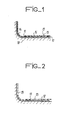
- a color television tube comprises a thick glass envelope having a front panel 10 on the internal surface 11 of which are deposited the phosphors 12, in points or in bands, which are selectively excited by three electron beams (not shown) generated by three electron guns inside the glass bulb.
- the color of each excited point triplet depends on the relative intensities of the electron beams.
- a hole mask (not shown) is usually provided near the phosphors inside the vacuum tube.
- the phosphors 12 are deposited directly on the internal surface II of the panel 10 and they are covered by a layer of aluminum 13 which has a double role: on the one hand to evacuate towards the mass the electrons striking the screen, and, on the other hand, reflect towards the front, that is to say towards the outside of the tube, the light emitted by the phosphors 12 towards the rear, that is to say towards the inside of the tube.
- the aluminum is also deposited around the screen so that this peripheral part 14, which is very often outside the case of the television, is opaque. In this way the tube does not have a transparent part, unsightly for the spectator.
- a layer 15 of organic material is deposited on the phosphors 12, comprising for example an emulsion of acrylic resins, polyvinyl alcohol and water.
- This layer 15, disposed on the face phosphors receiving the electrons have a smooth surface which makes it possible to obtain a substantially flat aluminum deposit 13.
- the tube is subjected to a heat treatment so that the internal deposits reach a temperature above 350 ° C. for which the microcrystals 16 and the organic layer 15 decompose.
- the gases resulting from this decomposition escape through the holes formed by the microcrystals 16. In this way the probability of blistering in the aluminum layer 13 ( Figure 2) is reduced.
- the aqueous solution which is sprayed onto the surface of the organic layer 15 is a solution of ammonium tetraborate, preferably hydrated ammonium tetraborate ENH 4 HB 4 O 7 ⁇ xH 2 O].
- This sprayed solution is then dried by blowing hot air or by different heating. At the end of this drying, microcrystals remain. Then, as already described, the aluminum layer 13 is deposited.
- the microcrystals of hydrated ammonium tetraborate undergo a significant reduction in volume because the water H 2 0 and the ammonia NH 3 escape in gaseous form. This leaves only a residue 17 of boric anhydride B 2 0 3 of small volume. This minimum residual volume makes it possible to reduce as much as possible the surface of the holes which remains obscured, which gives easier passage to the gases resulting from the decomposition of the organic layer 15.
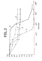
- Figure 3 is a diagram illustrating these comparative tests and other tests.
- the treatment temperature is plotted in d ° Celsius and on the ordinate, in%, the weight loss of the various layers.
- Curve 20 relates to hydrated ammonium tetraborate
- curve 21 represents the weight loss of boric acid, under the same concentration conditions.
- Curve 22 shows the weight loss of the borax of chemical formula [Na 2 B 4 O 7 .10 H 20J.
- Curve 23 relates to the use of ammonium oxalate and curve 24 shows the weight loss as a function of the temperature of layer 15.
- ammonium oxalate is an organic compound which evaporates completely and does not give rise to a residue making it possible to improve the adhesion between the phosphors and the aluminum layer and between glass and that layer of aluminum.
- curve 23 shows, the ammonium oxalate evaporates quickly; the risk of blistering is therefore high.
- borax Na 2 B 4 O 7 .10H 2 O
- ammonium tetraborate see curve 22.
- the residue left by the borax does not have the bonding properties of the residue B 2 0 3 '
Landscapes
- Formation Of Various Coating Films On Cathode Ray Tubes And Lamps (AREA)
- Cathode-Ray Tubes And Fluorescent Screens For Display (AREA)
Abstract
Description
- L'invention est relative à un procédé d'aluminisation de la face interne de l'écran d'un tube de télévision en couleurs.
- Un tube à rayons cathodiques pour la visualisation en couleurs, notamment un tube de télévision, présente un panneau frontal en verre dont la face interne est recouverte de phosphores, c'est-à-dire de substances luminescentes qui émettent de la lumière lorsqu'elles sont excitées par des faisceaux d'électrons produits par des canons à électrons à l'intérieur du tube. Ces phosphores sont déposés sur le verre sous forme de bandes ou de points et sont recouverts par une couche d'aluminium. Cette couche, connectée à la masse, est destinée à évacuer les électrons incidents et à constituer un miroir réfléchissant vers l'avant la lumière émise vers l'arrière du tube. Les phosphores formant une couche irrégulière, si l'on déposait directement l'aluminium sur ceux-ci le coefficient de réflexion de cette couche serait faible, ce qui irait à l'encontre du but recherché. C'est pourquoi sur les phosphores on dépose, avant la couche d'aluminium, une couche d'un matériau organique en solution (ou en émulsion dans l'eau) qui présente une surface lisse à l'opposé des phosphores et c'est sur cette surface lisse qu'on dépose ensuite l'aluminium. La matière organique est ensuite éliminée par traitement thermique à une température supérieure à 350° C. Au cours de ce traitement, cette matière se décompose en divers gaz qui s'échappent à travers l'aluminium qui est relativement poreux du fait de sa faible épaisseur. Mais cette porosité de l'aluminium est en général insuffisante. C'est pourquoi il peut se former des cloques ou boursouflures qui altèrent la réflectivité, et des parties de la couche métallique peuvent même se détacher, et ainsi perturber le fonctionnement des canons à électrons et/ou bloquer des trous du masque généralement utilisé pour la sélection des couleurs.
- Pour remédier à cet Inconvénient (la formation de cloques) on a déjà proposé (brevet US 3 821 009) de projeter sur la matière organique, une solution formant des cristaux destinés à percer la couche d'aluminium afin de faciliter l'échappement des gaz résultant de la décomposition de la matière organique.
- Mais les produits utilisés jusqu'à présent pour rendre rugueuse la surface de la matière organique sur laquelle doit être déposée la couche d'aluminium n'ont pas donné entière satisfaction car on a constaté, après fabrication d'un grand nombre de tubes, qu'une proportion non négligeable de ceux-ci présentait encore des cloques de la couche d'aluminium.
- L'invention permet de réduire la probabilité de formation de telles cloques.
- Elle est caractérisée en ce que la rugosité de la surface de la couche de matière organique recouvrant les phosphores et le verre autour de ces phosphores est obtenue par projection d'une solution, notamment aqueuse, ou d'une suspension de tétraborate d'ammonium, de préférence hydraté, [NH4 H B4O7·x H 2 0J.
- On a constaté qu'avec le procédé selon l'invention la probabilité de formation de cloques de la couche d'aluminium est particulièrement faible et que la quantité de produit à projeter sur la matière organique peut également être faible, ce qui réduit le coût de fabrication.
- En outre il subsiste, après traitement, un résidu d'anhydride bo rique B203 qui présente l'avantage d'augmenter l'adhérence entre l'aluminium et les phosphores et entre l'aluminium et le verre. En effet, l'anhydride borique reste stable aux températures maximales, généralement de l'ordre de 450 à 480° C, auquel le tube est soumis au cours de sa fabrication et, à ces températures, ce matériau forme une pâte d'une grande viscosité qui se répartit de façon uniforme entre l'aluminium et le verre et entre le matériau luminescent et l'aluminium. Toutefois, cette propriété d'amélioration de l'adhérence n'est pas spécifique au tétraborate d'ammonium car, lorsqu'on utilise, conformément à une technique connue, de l'acide borique, on obtient aussi, après traitement, un résidu d'anhydride borique B2O3.
- La diminution de la probabilité de formation de cloques de la couche d'aluminium et la diminution de la quantité de matériau projeté sur la matière organique résulte, selon les expériences effectuées par les inventeurs, des propriétés suivantes du tétraborate d'ammonium :
- Après projection et séchage, les microcristaux, qui percent la couche d'aluminium, sont plus petits et mieux répartis qu'avec les corps utilisés antérieurement. Il en résulte un plus grand nombre de trous dans la couche d'aluminium et donc une meilleure évacuation des gaz, d'où un moindre risque de formation de cloques. A cette minimisation du risque de formation de cloques contribue aussi le fait que, lorsque la température s'élève, le tétraborate d'ammonium hydraté se décompose, notamment par évaporation de l'eau, de façon progressive, sans discontinuité ; au contraire avec l'acide borique ou l'oxalate d'ammonium, ou encore le composé Na2 B4O7·IOH20, la décomposition est beaucoup plus rapide, la probabilité de formation de cloques étant d'autant plus grande que la vitesse de décomposition ou d'évaporation est importante.
- Par ailleurs on notera que la quantité de produit utilisé pouvant être très réduite, le résidu, après traitement thermique, est minime. Cette minimisation du résidu vitrifié assure une meilleure excitation des phosphores (le résidu formant un écran d'épaisseur réduite pour le faisceau d'électrons) et une plus grande réflexion de la lumière par la couche d'aluminium.
- D'autres caractéristiques et avantages de l'invention apparaîtront avec la description de certains de ses modes de réalisation, celle-ci étant effectuée en se référant aux dessins ci-annexés sur lesquels :
- - la figure 1 est un schéma partiel en coupe d'un tube de télévision en couleurs en cours de fabrication,
- - la figure 2 est un schéma analogue à celui de la figure 1 après traitement thermique, et
- - la figure 3 est un diagramme comparatif.
- Un tube de télévision en couleurs comprend une enveloppe en verre épais présentant un panneau frontal 10 sur la surface interne 11 duquel sont déposés les phosphores 12, en points ou en bandes, qui sont excités sélectivement par trois faisceaux d'électrons (non représentés) engendrés par trois canons à électrons à l'intérieur de l'ampoule de verre. La couleur de chaque triplet de points excité dépend des intensités relatives des faisceaux d'électrons. Pour qu'un faisceau d'électrons ne frappe qu'un phosphore de la couleur qu'il doit exciter on prévoit habituellement un masque à trous (non représenté) à proximité des phosphores à l'intérieur du tube sous vide.
- Les phosphores 12 sont déposés directement sur la surface interne Il du panneau 10 et ils sont recouverts par une couche d'aluminium 13 qui a un double rôle : d'une part évacuer vers la masse les électrons frappant l'écran, et, d'autre part, réfléchir vers l'avant, c'est-à-dire vers l'extérieur du tube, la lumière émise par les phosphores 12 vers l'arrière, c'est-à-dire vers l'intérieur du tube. L'aluminium est également déposé autour de l'écran afin que cette partie périphérique 14, qui est très souvent à l'extérieur du boîtier du téléviseur, soit opaque. De cette manière le tube ne présente pas de partie transparente, inesthétique pour le spectateur.
- Préalablement au dépôt de la couche d'aluminium on dépose sur les phosphores 12 une couche 15 d'une matière organique, comprenant par exemple une émulsion de résines acryliques, d'alcool polyvinylique et d'eau.Cette couche 15, disposée sur la face des luminophores recevant les électrons, présente une surface lisse qui permet d'obtenir un dépôt d'aluminium 13 sensiblement plat.
- Sur cette surface lisse de la couche 15 on projette une solution d'une matière cristallisable qui, après séchage, forme des microcristaux 16 d'une hauteur plus importante que l'épaisseur de la couche d'aluminium 13 qui sera déposée afin que celle-ci présente des trous.
- Après dépôt de la couche d'aluminium 13 le tube est soumis à un traitement thermique de façon que les dépôts internes atteignent une température supérieure à 350° C pour laquelle les microcristaux 16 et la couche organique 15 se décomposent. Les gaz résultant de cette décomposition s'échappent par les trous formés par les microcristaux 16. De cette manière la probabilité de formation de cloques dans la couche d'aluminium 13 (figure 2) est réduite.
- Conformément à l'invention la solution aqueuse qui est projetée sur la surface de la couche organique 15 est une solution de tétraborate d'ammonium, de préférence le tétraborate d'ammonium hydraté ENH4 H B4O7·xH2O].
- Cette solution projetée est ensuite séchée par soufflage d'air chaud ou par un chauffage différent. A l'issue de ce séchage il subsiste des microcristaux 16. Ensuite, comme déjà décrit, on dépose la couche d'aluminium 13.
- Au cours du traitement thermique les microcristaux de tétraborate d'ammonium hydraté subissent une réduction de volume importante car l'eau H20 et l'ammoniac NH3 s'échappent sous forme gazeuse. Il ne reste ainsi qu'un résidu 17 d'anhydride borique B203 de petit volume. Ce volume résiduel minimum permet de réduire au maximum la surface des trous qui reste occultée, ce qui donne un passage plus aisé aux gaz résultant de la décomposition de la couche organique 15.
- Ainsi la formation de cloques, tant sur l'écran proprement dit qu'autour de ce dernier, est moins probable avec un sel d'ammonium hydraté qu'avec les produits utilisés antérieurement.
- Dans des essais comparatifs entre une solution d'acide borique et une solution de tétraborate d'ammonium on a relevé les résultats suivants :
- - pour un panneau frontal,
- - avec des solutions à 3 % dans les deux cas,

- On constate ainsi que l'invention réduit considérablement le poids de résidus solides.
- Au cours des essais comparatifs on a constaté que les soufflages de cloques sous la couche d'aluminium étaient principalement provoqués par une brutale perte en eau dans la solution d'acide borique. Entre 100° C et 150° C, cette perte brutale provoque un flux de vapeur d'eau responsable de la formation de cloques. Une solution selon l'invention, en concentrations comparables, subit une perte en eau beaucoup plus progressive.
- La figure 3 est un diagramme illustrant ces essais comparatifs et d'autres essais. En abscisses on a porté la température de traitement en d° Celsius et en ordonnées, en %, la perte en poids des diverses couches. La courbe 20 se rapporte au tétraborate d'ammonium hydraté, la courbe 21 représente la perte de poids d'acide borique, dans les mêmes conditions de concentration. La courbe 22 montre la perte en poids du borax de formule chimique [Na2B4O7.10 H 20J. La courbe 23 se rapporte à l'utilisation de l'oxalate d'ammonium et la courbe 24 montre la perte de poids en fonction de la température de la couche 15.
- Les recherches effectuées par les inventeurs ont montré que l'oxalate d'ammonium est un composé organique qui s'évapore complètement et ne donne pas lieu à un résidu permettant d'améliorer l'adhérence entre les phosphores et la couche d'aluminium et entre le verre et cette couche d'aluminium. De plus, comme le montre la courbe 23 l'oxalate d'ammonium s'évapore rapidement ; le risque de formation de cloques est donc élevé.
- L'acide borique laisse, après décomposition, un résidu B203 améliorant ladite adhérence. Le tétraborate d'ammonium laisse le même résidu. Toutefois, l'avantage de cette dernière substance par rapport à l'acide borique est, comme on peut le voir à l'examen des courbes 20 et 21, que la vitesse de décomposition du tétraborate d'ammonium est moins importante que la vitesse de décomposition de l'acide borique ; ainsi avec le tétraborate d'ammonium le risque de formation de cloques est moins élevé.
- Enfin, le borax [Na2B4O7.10H2O] se décompose également plus rapidement que le tétraborate d'ammonium (voir courbe 22). Le risque de formation de cloques est ainsi plus élevé. De plus, le résidu laissé par le borax n'a pas les propriétés de collage du résidu B2 03'
Claims (2)
Applications Claiming Priority (2)
| Application Number | Priority Date | Filing Date | Title |
|---|---|---|---|
| FR8315338A FR2552584B1 (fr) | 1983-09-27 | 1983-09-27 | Procede d'aluminisation de la face interne de l'ecran d'un tube de television en couleurs |
| FR8315338 | 1983-09-27 |
Publications (2)
| Publication Number | Publication Date |
|---|---|
| EP0143021A1 true EP0143021A1 (fr) | 1985-05-29 |
| EP0143021B1 EP0143021B1 (fr) | 1987-05-06 |
Family
ID=9292576
Family Applications (1)
| Application Number | Title | Priority Date | Filing Date |
|---|---|---|---|
| EP84401895A Expired EP0143021B1 (fr) | 1983-09-27 | 1984-09-21 | Procédé d'aluminisation de la face interne de l'écran d'un tube de télévision en couleurs |
Country Status (5)
| Country | Link |
|---|---|
| US (1) | US4590092A (fr) |
| EP (1) | EP0143021B1 (fr) |
| JP (1) | JPH067455B2 (fr) |
| DE (1) | DE3463587D1 (fr) |
| FR (1) | FR2552584B1 (fr) |
Families Citing this family (10)
| Publication number | Priority date | Publication date | Assignee | Title |
|---|---|---|---|---|
| CA1267684A (fr) * | 1985-09-12 | 1990-04-10 | Hiroshi Kato | Ecran cathodique couleur du type a indexation |
| JPH0227636A (ja) * | 1988-07-15 | 1990-01-30 | Sony Corp | 受像管螢光面の形成方法 |
| EP0382554A3 (fr) * | 1989-02-10 | 1992-09-30 | Matsushita Electric Industrial Co., Ltd. | Procédé pour la construction d'un revêtement arrière métallique et procédé pour le montage d'une anode |
| US5264478A (en) * | 1991-08-21 | 1993-11-23 | Samsung Electron Devices Co., Ltd. | Filming liquid composition for color braun tubes |
| JP2536409B2 (ja) * | 1993-06-08 | 1996-09-18 | 日本電気株式会社 | 陰極線管の蛍光面形成方法 |
| AU2110199A (en) | 1998-01-09 | 1999-07-26 | Metabolix, Inc. | Polymer compositions providing low residue levels and methods of use thereof |
| ITMI991155A1 (it) | 1999-05-25 | 2000-11-25 | Videocolor Spa | Metodo per metallizzare uno schermo luminescente |
| KR100331452B1 (ko) * | 2000-05-29 | 2002-04-09 | 김순택 | 잔류 유기물 저감을 위한 형광체 스크린 형성 방법 |
| JP2002343241A (ja) * | 2001-05-10 | 2002-11-29 | Toshiba Corp | メタルバック付き蛍光面の形成方法および画像表示装置 |
| JP4952974B2 (ja) * | 2005-11-18 | 2012-06-13 | カシオ計算機株式会社 | レンズカバー及びデジタルカメラ |
Citations (3)
| Publication number | Priority date | Publication date | Assignee | Title |
|---|---|---|---|---|
| US3821009A (en) * | 1972-04-28 | 1974-06-28 | Zenith Radio Corp | Method of aluminizing a cathode-ray tube screen |
| US4123563A (en) * | 1977-02-23 | 1978-10-31 | Hitachi, Ltd. | Process for the production of color television picture tubes |
| US4339475A (en) * | 1979-03-23 | 1982-07-13 | Hitachi, Ltd. | Method of forming a fluorescent screen for cathode-ray tube |
Family Cites Families (2)
| Publication number | Priority date | Publication date | Assignee | Title |
|---|---|---|---|---|
| US2910376A (en) * | 1957-03-27 | 1959-10-27 | Rca Corp | Method of aluminizing phosphor screens |
| US4025661A (en) * | 1972-11-13 | 1977-05-24 | Rca Corporation | Method of making viewing-screen structure for a cathode-ray tube |
-
1983
- 1983-09-27 FR FR8315338A patent/FR2552584B1/fr not_active Expired
-
1984
- 1984-09-21 DE DE8484401895T patent/DE3463587D1/de not_active Expired
- 1984-09-21 EP EP84401895A patent/EP0143021B1/fr not_active Expired
- 1984-09-25 JP JP59198741A patent/JPH067455B2/ja not_active Expired - Lifetime
- 1984-09-26 US US06/654,614 patent/US4590092A/en not_active Expired - Lifetime
Patent Citations (3)
| Publication number | Priority date | Publication date | Assignee | Title |
|---|---|---|---|---|
| US3821009A (en) * | 1972-04-28 | 1974-06-28 | Zenith Radio Corp | Method of aluminizing a cathode-ray tube screen |
| US4123563A (en) * | 1977-02-23 | 1978-10-31 | Hitachi, Ltd. | Process for the production of color television picture tubes |
| US4339475A (en) * | 1979-03-23 | 1982-07-13 | Hitachi, Ltd. | Method of forming a fluorescent screen for cathode-ray tube |
Non-Patent Citations (1)
| Title |
|---|
| PATENT ABSTRACTS OF JAPAN, vol. 4, no. 28 (E-1)(510), 8 mars 1980, page 36 E 1; & JP-A-55 001 035 (MATSUSHITA DENSHI KOGYO K.K.) 07-01-1980 * |
Also Published As
| Publication number | Publication date |
|---|---|
| JPH067455B2 (ja) | 1994-01-26 |
| US4590092A (en) | 1986-05-20 |
| DE3463587D1 (en) | 1987-06-11 |
| JPS60150537A (ja) | 1985-08-08 |
| EP0143021B1 (fr) | 1987-05-06 |
| FR2552584A1 (fr) | 1985-03-29 |
| FR2552584B1 (fr) | 1986-03-21 |
Similar Documents
| Publication | Publication Date | Title |
|---|---|---|
| EP0143021B1 (fr) | Procédé d'aluminisation de la face interne de l'écran d'un tube de télévision en couleurs | |
| KR930000389B1 (ko) | 섬광 감소 및 정전 방지성 규산염 코팅을 가진 음극선관 | |
| FR2713825A1 (fr) | Source lumineuse à filtre optique interférentiel, procédé de formation d'un tel filtre et système d'éclairage muni d'une telle source lumineuse. | |
| US4201797A (en) | Process for applying a light-absorbing, electron permeable layer within an image intensifier tube | |
| FR2512273A1 (fr) | Lampe a vapeur de metal alcalin haute pression | |
| FR2462020A1 (fr) | Ecran luminescent a structure en forme de trame et utilisation de ce dernier | |
| FR2482139A1 (fr) | Procede permettant de munir une piece metallique d'une surface noire, et cathode obtenue par ce procede | |
| FR2757311A1 (fr) | Recipient a vide | |
| FR2509090A1 (fr) | Procede de fabrication d'un tube a rayons cathodiques | |
| JP4164992B2 (ja) | 陰極線管及びその製造方法 | |
| US5723170A (en) | Method of forming fluorescent screen of cathode ray tube | |
| FR2515423A1 (fr) | Ecran d'entree pour tube amplificateur de brillance et procede pour la realisation d'un tel ecran | |
| EP1173877B1 (fr) | Dispositif a emission de champ utilisant un gaz reducteur et fabrication d'un tel dispositif | |
| DE2045198A1 (de) | Verfahren und Vorrichtung zur Erzeu gung dunner Schichten auf Oberflachen durch Verdampfen des die Schicht bildenden Stoffes im Vakuum | |
| US4547699A (en) | Green luminescing cathode-ray tube device | |
| US2106754A (en) | Electric discharge device | |
| FR2847904A1 (fr) | Luminophore de couleurs chaudes lumineuses et disositif d'affichage fluorescent. | |
| FR2657619A1 (fr) | Procede pour fabriquer un element convertisseur transformant une lumiere d'une longueur d'onde donnee en une lumiere de longueur d'onde differente. | |
| FR2564638A1 (fr) | Tube a rayons cathodiques a canon en ligne | |
| FR2481515A1 (fr) | Procede de preparation d'un ecran luminescent, notamment pour un tube cathodique | |
| JPS6032234A (ja) | 陰極線管のフィルミング膜形成法 | |
| CN102378512A (zh) | 壳体及其制作方法 | |
| BE474818A (fr) | ||
| JPS5828696B2 (ja) | イメ−ジ管用螢光面の製造方法 | |
| JPS6036058B2 (ja) | 陰極線管の映像スクリ−ン形成方法 |
Legal Events
| Date | Code | Title | Description |
|---|---|---|---|
| PUAI | Public reference made under article 153(3) epc to a published international application that has entered the european phase |
Free format text: ORIGINAL CODE: 0009012 |
|
| AK | Designated contracting states |
Designated state(s): DE FR GB IT NL |
|
| 17P | Request for examination filed |
Effective date: 19850601 |
|
| 17Q | First examination report despatched |
Effective date: 19860228 |
|
| GRAA | (expected) grant |
Free format text: ORIGINAL CODE: 0009210 |
|
| AK | Designated contracting states |
Kind code of ref document: B1 Designated state(s): DE FR GB IT NL |
|
| ITF | It: translation for a ep patent filed | ||
| REF | Corresponds to: |
Ref document number: 3463587 Country of ref document: DE Date of ref document: 19870611 |
|
| PLBE | No opposition filed within time limit |
Free format text: ORIGINAL CODE: 0009261 |
|
| STAA | Information on the status of an ep patent application or granted ep patent |
Free format text: STATUS: NO OPPOSITION FILED WITHIN TIME LIMIT |
|
| 26N | No opposition filed | ||
| ITTA | It: last paid annual fee | ||
| PGFP | Annual fee paid to national office [announced via postgrant information from national office to epo] |
Ref country code: GB Payment date: 19980727 Year of fee payment: 15 |
|
| PGFP | Annual fee paid to national office [announced via postgrant information from national office to epo] |
Ref country code: FR Payment date: 19980803 Year of fee payment: 15 |
|
| PGFP | Annual fee paid to national office [announced via postgrant information from national office to epo] |
Ref country code: DE Payment date: 19980915 Year of fee payment: 15 |
|
| PGFP | Annual fee paid to national office [announced via postgrant information from national office to epo] |
Ref country code: NL Payment date: 19980930 Year of fee payment: 15 |
|
| PG25 | Lapsed in a contracting state [announced via postgrant information from national office to epo] |
Ref country code: GB Free format text: LAPSE BECAUSE OF NON-PAYMENT OF DUE FEES Effective date: 19990921 |
|
| PG25 | Lapsed in a contracting state [announced via postgrant information from national office to epo] |
Ref country code: NL Free format text: LAPSE BECAUSE OF NON-PAYMENT OF DUE FEES Effective date: 20000401 |
|
| GBPC | Gb: european patent ceased through non-payment of renewal fee |
Effective date: 19990921 |
|
| PG25 | Lapsed in a contracting state [announced via postgrant information from national office to epo] |
Ref country code: FR Free format text: LAPSE BECAUSE OF NON-PAYMENT OF DUE FEES Effective date: 20000531 |
|
| NLV4 | Nl: lapsed or anulled due to non-payment of the annual fee |
Effective date: 20000401 |
|
| PG25 | Lapsed in a contracting state [announced via postgrant information from national office to epo] |
Ref country code: DE Free format text: LAPSE BECAUSE OF NON-PAYMENT OF DUE FEES Effective date: 20000701 |
|
| REG | Reference to a national code |
Ref country code: FR Ref legal event code: ST |