EP0143549A1 - Mécanisme de rotation en précision pour la rotation légère d'un objet - Google Patents
Mécanisme de rotation en précision pour la rotation légère d'un objet Download PDFInfo
- Publication number
- EP0143549A1 EP0143549A1 EP84307340A EP84307340A EP0143549A1 EP 0143549 A1 EP0143549 A1 EP 0143549A1 EP 84307340 A EP84307340 A EP 84307340A EP 84307340 A EP84307340 A EP 84307340A EP 0143549 A1 EP0143549 A1 EP 0143549A1
- Authority
- EP
- European Patent Office
- Prior art keywords
- members
- driving
- sections
- fixing
- movable
- Prior art date
- Legal status (The legal status is an assumption and is not a legal conclusion. Google has not performed a legal analysis and makes no representation as to the accuracy of the status listed.)
- Granted
Links
- 230000007246 mechanism Effects 0.000 title claims description 28
- 230000008878 coupling Effects 0.000 claims abstract description 9
- 238000010168 coupling process Methods 0.000 claims abstract description 9
- 238000005859 coupling reaction Methods 0.000 claims abstract description 9
- 230000008602 contraction Effects 0.000 claims description 13
- 230000003247 decreasing effect Effects 0.000 description 4
- 238000001015 X-ray lithography Methods 0.000 description 1
- 239000000853 adhesive Substances 0.000 description 1
- 230000001070 adhesive effect Effects 0.000 description 1
- 238000010894 electron beam technology Methods 0.000 description 1
- 238000009413 insulation Methods 0.000 description 1
- 238000005259 measurement Methods 0.000 description 1
- 238000012986 modification Methods 0.000 description 1
- 230000004048 modification Effects 0.000 description 1
- 239000004065 semiconductor Substances 0.000 description 1
- 239000000758 substrate Substances 0.000 description 1
Images

Classifications
-
- H—ELECTRICITY
- H02—GENERATION; CONVERSION OR DISTRIBUTION OF ELECTRIC POWER
- H02N—ELECTRIC MACHINES NOT OTHERWISE PROVIDED FOR
- H02N2/00—Electric machines in general using piezoelectric effect, electrostriction or magnetostriction
- H02N2/10—Electric machines in general using piezoelectric effect, electrostriction or magnetostriction producing rotary motion, e.g. rotary motors
- H02N2/101—Electric machines in general using piezoelectric effect, electrostriction or magnetostriction producing rotary motion, e.g. rotary motors using intermittent driving, e.g. step motors
Definitions
- This invention relates to a fine or precise rotation mechanism for rotating, with high precision, an object to a desired position.
- an electron beam drawing system a reduction projection type transfer system and an X-ray lithography system have been developed as systems for forming a fine pattern on an object such as a semiconductor wafer and a mask substrate.
- This type of apparatus requires a driving mechanism for slightly and precisely moving a sample on the order of submicrons. High precision, fine driving mechanisms are required not only for the systems mentioned above, but also in technical fields where precise measurements are required.
- Fine driving mechanisms include those in which an object is moved linearly in one direction and those in which an object is rotated.
- the prior art fine rotation mechanisms for causing a rotating motion have the following problems. With a driving mechanism where the rotating stroke is large, it is difficult to obtain slight motion. On the other hand, with a driving mechanism where slight motion is possible, it is impossible to provide a large rotating stroke.
- Rotational driving members i.e., piezoelectric elements which can be elongated and contracted according to the voltage applied to them, are arranged on a rotating table, and high voltage cords are connected to the rotational driving members to drive them.
- the rotating table can be rotated at any speed.
- the cords are twisted, and the rotating table can be rotated only by a predetermined number of revolutions.
- the cords are brought into slidable contact with fixed members to be damaged thereby, resulting in incomplete electric insulation.
- a precise rotation mechanism comprising: a base member; a rotatable member; means for rotatably supporting said rotatable member; first and second driving members capable of elongation and contraction; first and second supporting members fixed on said base member, for supporting said first and second driving members fixed thereon; first and second movable sections driving on said first and second fixed members and moved by contraction and elongation of said first and second driving members, respectively; first and second fixing members for fixing said first and second movable sections to said first and second rotatable members respectively; and energizing means for energizing said first and second driving members and said first and second fixing members to rate the rotatable member.
- said first fixing member in a first step, is energized to fix said first movable section to said rotatable member, and said first driving member is energized to cause said first driving member to elongate or contract so as to slightly rotate said rotatable member together with said first movable section.
- said second fixing member is energized to fix said second movable .section to said rotatable member, and said first fixing member is deenergized to release said first movable section from said rotatable member.
- said second fixing member is energized to fix said second movable section to said rotatable member
- said second driving member is energized to cause said second driving member to elongate or contract so as to slightly rotate said rotatable member together with said second movable section.
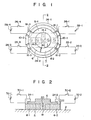
- a precise rotation mechanism which slightly rotates, with high precision, an object to a desired position according to an embodiment of the present invention, will be described with reference to Figs. 1 and 2.
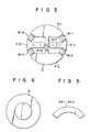
- a drive disk 4 shown in Fig. 3 is placed on a flat and smooth surface of a base 2, and a rotating disk 6 shown in Fig. 4 is rotatably mounted on the disk surface of the drive disk 4.
- the drive disk 4 comprises movable sections 8-1 and 8-2 and fixed sections 10-1 and 10-2, coupled by a coupling section 12 located at the center of the drive disk 4 as shown in Fig. 3.
- the fixed sections 10-1 and 10-2 are fixed on the base 2 with bolts or the like.
- the movable sections 8-1 and .8-2 are coupled to the coupling section 12 of the drive disk 4 through elastic hinges 14-1 and 14-2 so as to swing on the base 2 about the center of the drive disk 4.
- the movable sections 8-1 and 8-2 are coupled to the fixed sections 10-1 and 10-2 by driving members 16-1, 16-2, 16-3 and 16-4 made of piezoelectric elements, which are elongated/contracted upon application of a voltage to slightly move the movable sections 8-1 and 8-2.
- the driving members 16-1, 16-2, 16-3 and 16-4 are supported by an adhesive or screws in spaces between the moving sections and the fixed sections.
- the rotating disk 6 mounted on the drive disk 4 is rotatably supported by a pivot bearing.
- This pivot bearing is obtained such that a pivot 18 fixed on the coupling section 12 is rotatably inserted in a recess 20 formed at the center of the lower surface of the rotating disk 6.
- Fixing members 24-1 and 24-2 are arranged around the movable sections 8-1 and 8-2 and are made of the piezoelectric elements subjected to elongation and contraction along the axial direction (indicated by arrow 22) of the mechanism upon application of a voltage, as shown in Fig. 5.
- the fixing members 24-1 and 24-2 are respectively fixed to the movable sections 8-1 and 8-2.
- the rotating disk 6 is urged by one of the fixing members 24-1 and 24-2 against the movable sections 8-1 and 8-2 and is movable together with the movable sections 8-1 and 8-2.
- the driving members 16-1, 16-2, 16-3 and 16-4 are connected to power sources 28-1, 28-1, 28-3 and 28-4 through switching elements 26-1, 26-2, 26-3 and 26-4, respectively.
- the fixing members 24-1 and 24-2 are connected to power sources 32-1 and 32-2 through switching elements 30-1 and 30-2, respectively.
- the switching element 30-1 is closed at time tl, and a voltage is applied to the fixing member 24-1, as shown in Fig. 6A.
- the fixing member 24-1 is contracted to fix the rotating disk 6 to the movable section 8-1.
- Fig. 6B to the voltage applied to the driving member 16-1 is gradually decreased.
- a voltage applied to the driving member 16-4 is gradually increased, so that the driving member 16-4 is contracted. Therefore, the movable section 8-1 and the rotating disk 6 fixed thereto are slightly rotated counterclockwise in accordance with elongation and contraction of the driving members 16-1 and 16-4.
- a voltage applied to the driving member 16-2 through the switching element 26-2 is gradually decreased, as shown in Fig. 6D, so that the driving member 16-2 is elongated.
- a voltage applied to the driving member 16-3 through the switching element 26-3 is gradually increased to contract the driving member 16-3. Therefore, the movable section 8-2 is slightly rotated clockwise opposite to the rotational direction of the movable section 8-1 upon elongation and contraction of the driving members 16-4 and 16-2.
- the fixing member 24-2 will not be contracted but is kept elongated so as to guarantee rotation of the rotating disk 6.
- the switching element 30-2 is closed at time t2, and a voltage is applied to the fixing member 24-2, as shown in Fig. 6F.
- the fixing member 24-2 is contracted, and the rotating disk 6 is fixed to the movable section 8-2.
- the switching element 30-1 is opened to deenergize the fixing member 24-1, so that the fixing member 24-1 is elongated, and the rotating disk 6 is released from the movable section 8-1.
- a voltage applied to the driving member 16-2 is gradually increased, as shown in Fig. 6D.
- the driving member 16-2 is contracted.
- a voltage applied to the driving member 16-3 is gradually decreased, thereby elongating the driving member 16-3.
- the movable section 8-2 and the rotating disk 6 fixed thereto are slightly rotated counterclockwise upon contraction and elongation of the driving members 16-2 and 16-4.
- the voltage applied to the driving member 16-4 through-the switching element 26-4 is gradually decreased, as shown in Fig. 6C, so that the driving member 16-4 is elongated.
- the voltage applied to the driving member 16-1 through the switching element 26-1 is gradually increased, thereby contracting the driving member 16-1. Therefore, the movable section 8-1 is slightly rotated counterclockwise opposite to the rotational direction of the movable section 8-1 upon elongation and contraction of the driving members 16-1 and 16-4.
- the rotating disk 6 continues to slightly rotate around the pivot bearing due to the movement of the movable sections 8-1 and 8-2.
- the rotating disk 6 can be rotated clockwise upon application of voltages to the driving members 16-1, 16-2, 16-3 and 16-4 in such a manner that they can alternate between elongation and contraction.
- the rotating disk 6 can rotate as many times as possible without being interfered with by cords or the like and can also be slightly rotated.
- the level of the voltage applied to the driving member can be adjusted to perform coarse and fine rotation of the rotating disk.
- the cycle of contraction and elongation of the driving member can be shortened to vibrate movable sections 8-1 and 8-2 at a relatively high speed, thereby rotating the rotating disk at high speed.
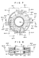
- bearings 38-1 and 38-2 comprising ball bearings are fixed in a hollow cylindrical housing 34.
- a rotating cylinder 36 having a rotating disk 40 adapted to receive the driving force is rotatably supported by the bearings 38-1 and 38-2.
- Bearings 42-1, 42-2, 42-3 and 42-4 comprising ball bearings are fixed to the rotating cylinder 36.
- Movable sections 44-1, 44-2, 44-3 and 44-4 symmetrical about the axis of the rotating cylinder 36 are mounted on the bearings 42-1, 42-2, 42-3 and 42-4, respectively, and can be supported by the rotating cylinder 36 to be slightly rotated around the rotating cylinder 36.
- Fixing members 46-1, 46-2, 46-3 and 46-4 made of piezoelectric elements, which are elongated and contracted upon application of voltages thereto, are arranged in the movable sections 44-1, 44-2, 44-3 and 44-4, respectively.
- the fixing members 46-1, 46-2, 46-3 and 46-4 are connected to power sources 50-1, 50-2, 50-3 and 50-4 through switching elements 48-1, 48-2, 48-3 and 48-4, respectively.
- Fixing sections 52-1, 52-2, 52-3 and 52-4 corresponding to the movable sections 44-1, 44-2, 44-3 and 44-4 are formed on the inner surface of the hollow cylindrical housing 34.
- the fixing sections 52-1, 52-2, 52-3 and 52-4 are coupled to the movable sections 44-1, 44-2, 44-3 and 44-4 through driving members 16-1, 16-2, 16-3 and 16-4 made of piezoelectric elements, which are contracted and elongated upon application voltages thereto, respectively.
- the rotating cylinder 34 is rotated in the following manner.
- Switching elements 48-1 and 48-2 are opened to elongate the fixing members 46-1 and 46-2, so that the movable sections 44-1 and 44-4 are coupled to the rotating disk 40 by the fixing members 46-1 and .46-4.
- the driving members 16-1 and 16-4 are elongated to slightly rotate the rotating disk 40 together with the movable sections 44-1 and 44-4.
- the rotating cylinder 36 is slightly rotated in a counterclockwise direction.
- the switching elements 48-2 and 48-3 are opened to elongate the fixing members 46-2 and 46-3, so that the movable sections 44-2 and 44-3 are coupled to the rotating disk 40 by the fixing members 46-2 and 46-3.
- the switching elements 48-1 and 48-4 are closed to contract the fixing members 46-1 and 46-4, so that the movable sections 44-1 and 44-4 are released from the rotating disk 40.
- the driving members 16-1 and 16-4 are contracted, and at the same time, the driving members 16-2 and 16-3 are contracted while the movable sections 44-2 and 44-3 are coupled to the rotating disk 40, so that the rotating disk 40 is slightly rotated together with the movable'sections 44-2 and 44-3.
- the rotating cylinder 36 is slightly rotated in the counterclockwise direction.
- the rotating cylinder 36 continues to slightly rotate upon movement of the movable sections.
- the rotating cylinder can be rotated clockwise by applying the voltages to the driving members 16-1, 16-2, 16-3 and 16-4 in such a manner elongation and contraction are alternated.
- the rotating cylinder 36 can rotate as many times as possible without being interfered with by cords or the like and can be slightly rotated.
- the level of the voltage applied to the driving member can be adjusted to perform coarse and fine rotation of the rotating disk.
- the cycle of contraction and elongation of the driving member can be shortened to vibrate movable sections at a relatively high speed, thereby rotating the rotating disk at high speed.
- the present invention is not limited to the particular embodiments described above. Various changes and modifications may be made within the spirit and scope of the invention.
- an electrostatic chuck may be used in place of the fixing members.
- the centering means is not limited to the pivot bearing or ball bearing, but may be extended to a roller bearing, an air bearing or any other bearing.
- at least two driving members need to be used to move the movable section, so that the number of driving members is not limited.
Landscapes
- General Electrical Machinery Utilizing Piezoelectricity, Electrostriction Or Magnetostriction (AREA)
- Control Of Position Or Direction (AREA)
Applications Claiming Priority (2)
| Application Number | Priority Date | Filing Date | Title |
|---|---|---|---|
| JP225701/83 | 1983-11-30 | ||
| JP58225701A JPS60118072A (ja) | 1983-11-30 | 1983-11-30 | 回転微動機構 |
Publications (2)
| Publication Number | Publication Date |
|---|---|
| EP0143549A1 true EP0143549A1 (fr) | 1985-06-05 |
| EP0143549B1 EP0143549B1 (fr) | 1987-09-02 |
Family
ID=16833440
Family Applications (1)
| Application Number | Title | Priority Date | Filing Date |
|---|---|---|---|
| EP84307340A Expired EP0143549B1 (fr) | 1983-11-30 | 1984-10-25 | Mécanisme de rotation en précision pour la rotation légère d'un objet |
Country Status (4)
| Country | Link |
|---|---|
| US (1) | US4578607A (fr) |
| EP (1) | EP0143549B1 (fr) |
| JP (1) | JPS60118072A (fr) |
| DE (1) | DE3465837D1 (fr) |
Cited By (2)
| Publication number | Priority date | Publication date | Assignee | Title |
|---|---|---|---|---|
| GB2160026A (en) * | 1984-04-21 | 1985-12-11 | Deutsche Forsch Luft Raumfahrt | Rotational virbration drive for a ring laser gyroscope |
| CN105391337A (zh) * | 2015-11-26 | 2016-03-09 | 西安交通大学 | 压电堆及马达混合驱动的大扭矩大行程旋转作动器及方法 |
Families Citing this family (14)
| Publication number | Priority date | Publication date | Assignee | Title |
|---|---|---|---|---|
| JPH0648910B2 (ja) * | 1987-02-12 | 1994-06-22 | 日本電気株式会社 | 圧電モ−タ |
| US5969464A (en) * | 1989-04-18 | 1999-10-19 | Minolta Co., Ltd. | Drive device using electromechanical transducer and an apparatus employing the drive device |
| US5041753A (en) * | 1990-10-11 | 1991-08-20 | The United States Of America As Represented By The Secretary Of The Navy | High torque magnetic angular positioning motor |
| US5341056A (en) * | 1991-01-18 | 1994-08-23 | The United States Of America As Represented The Secretary Of The Navy | Magnetostrictive motor system |
| JPH04372324A (ja) * | 1991-06-21 | 1992-12-25 | Toyoda Mach Works Ltd | 送り装置 |
| US5281884A (en) * | 1992-06-03 | 1994-01-25 | At&T Bell Laboratories | Adjustable X-Y stage |
| US5432395A (en) * | 1993-08-02 | 1995-07-11 | Bonneville Scientific Incorporated | Direct-drive field actuator motors |
| JP3233901B2 (ja) * | 1998-05-22 | 2001-12-04 | セントラル技研工業株式会社 | 超音波振動によるスクリューロッド駆動機構 |
| US6518689B2 (en) * | 2000-02-18 | 2003-02-11 | Honeywell Federal Manufacturing & Technologies, Llc | Piezoelectric wave motor |
| GB2369489B (en) * | 2000-11-23 | 2004-03-10 | Khaled Karrai | Inertial rotation device |
| DE10156836B4 (de) * | 2001-11-20 | 2004-01-29 | Fraunhofer-Gesellschaft zur Förderung der angewandten Forschung e.V. | Vorrichtung zur Erzeugung einer rotatorischen Bewegung und Verwendung derselben |
| US7196453B2 (en) * | 2005-05-23 | 2007-03-27 | United States Of America As Represented By The Secretary Of The Army | High-efficiency radial piezoelectric motor |
| JP5563581B2 (ja) * | 2008-10-09 | 2014-07-30 | ニューカッスル イノベイション リミテッド | 位置決めシステムおよび方法 |
| US9482928B2 (en) | 2013-03-15 | 2016-11-01 | Quantel USA, Inc. | Apparatus for facilitating micro-rotational calibration for an NLO crystal enabled laser system |
Citations (5)
| Publication number | Priority date | Publication date | Assignee | Title |
|---|---|---|---|---|
| US3377489A (en) * | 1964-11-06 | 1968-04-09 | Int Standard Electric Corp | Position control device |
| DE1933205A1 (de) * | 1969-06-26 | 1971-01-07 | Siemens Ag | Mikroschritt-Motor |
| US3952215A (en) * | 1971-04-21 | 1976-04-20 | Hitachi, Ltd. | Stepwise fine adjustment |
| EP0085745A2 (fr) * | 1982-02-09 | 1983-08-17 | Kabushiki Kaisha Toshiba | Mécanisme fin de rotation |
| FR2522216A1 (fr) * | 1982-02-25 | 1983-08-26 | Toshiiku Sashida | Dispositif moteur utilisant une oscillation ultrasonore |
Family Cites Families (7)
| Publication number | Priority date | Publication date | Assignee | Title |
|---|---|---|---|---|
| JPS5112497A (en) * | 1974-07-22 | 1976-01-31 | Kyoritsu Kk | Chensoono hanpatsubooshisoochi |
| JPS5315060A (en) * | 1976-07-28 | 1978-02-10 | Hitachi Ltd | Inching device |
| US4219755A (en) * | 1977-03-18 | 1980-08-26 | Physics International Company | Electromotive actuator |
| EP0071666B1 (fr) * | 1981-08-10 | 1985-02-06 | International Business Machines Corporation | Support mobile électrique |
| US4455501A (en) * | 1982-02-09 | 1984-06-19 | Tokyo Shibaura Denki Kabushiki Kaisha | Precision rotation mechanism |
| JPS6044838B2 (ja) * | 1982-04-28 | 1985-10-05 | 株式会社東芝 | 回転微動機構 |
| JPS5976184A (ja) * | 1982-10-22 | 1984-05-01 | Hitachi Ltd | アクチユエ−タ |
-
1983
- 1983-11-30 JP JP58225701A patent/JPS60118072A/ja active Pending
-
1984
- 1984-10-25 EP EP84307340A patent/EP0143549B1/fr not_active Expired
- 1984-10-25 DE DE8484307340T patent/DE3465837D1/de not_active Expired
- 1984-10-26 US US06/664,964 patent/US4578607A/en not_active Expired - Fee Related
Patent Citations (5)
| Publication number | Priority date | Publication date | Assignee | Title |
|---|---|---|---|---|
| US3377489A (en) * | 1964-11-06 | 1968-04-09 | Int Standard Electric Corp | Position control device |
| DE1933205A1 (de) * | 1969-06-26 | 1971-01-07 | Siemens Ag | Mikroschritt-Motor |
| US3952215A (en) * | 1971-04-21 | 1976-04-20 | Hitachi, Ltd. | Stepwise fine adjustment |
| EP0085745A2 (fr) * | 1982-02-09 | 1983-08-17 | Kabushiki Kaisha Toshiba | Mécanisme fin de rotation |
| FR2522216A1 (fr) * | 1982-02-25 | 1983-08-26 | Toshiiku Sashida | Dispositif moteur utilisant une oscillation ultrasonore |
Cited By (3)
| Publication number | Priority date | Publication date | Assignee | Title |
|---|---|---|---|---|
| GB2160026A (en) * | 1984-04-21 | 1985-12-11 | Deutsche Forsch Luft Raumfahrt | Rotational virbration drive for a ring laser gyroscope |
| CN105391337A (zh) * | 2015-11-26 | 2016-03-09 | 西安交通大学 | 压电堆及马达混合驱动的大扭矩大行程旋转作动器及方法 |
| CN105391337B (zh) * | 2015-11-26 | 2017-09-12 | 西安交通大学 | 压电堆及马达混合驱动的大扭矩大行程旋转作动器及方法 |
Also Published As
| Publication number | Publication date |
|---|---|
| DE3465837D1 (en) | 1987-10-08 |
| US4578607A (en) | 1986-03-25 |
| EP0143549B1 (fr) | 1987-09-02 |
| JPS60118072A (ja) | 1985-06-25 |
Similar Documents
| Publication | Publication Date | Title |
|---|---|---|
| US4578607A (en) | Piezoelectric precise rotation mechanism for slightly rotating an object | |
| EP0166499B1 (fr) | Mécanisme de déplacement de précision | |
| US4455501A (en) | Precision rotation mechanism | |
| EP0160707B1 (fr) | Dispositif de déplacement rotatif pas à pas piézo-électrique | |
| EP0085745B1 (fr) | Mécanisme fin de rotation | |
| KR920002244A (ko) | 소경금속관 굴곡 방법 및 장치 | |
| JPS61159349A (ja) | 微小変位移動装置 | |
| JPS6044838B2 (ja) | 回転微動機構 | |
| JPH0527034Y2 (fr) | ||
| US7309946B2 (en) | Motion actuator | |
| JPH0358855B2 (fr) | ||
| JPS63274894A (ja) | 送り装置 | |
| JPH0412838B2 (fr) | ||
| JPS61244432A (ja) | 回動装置 | |
| JPH02142365A (ja) | バイモルフモータ | |
| JP3173261B2 (ja) | 静電アクチュエータ | |
| JPS5983581A (ja) | 回転微動機構 | |
| JP2603239Y2 (ja) | 表面分析装置 | |
| JPS58190079A (ja) | 微動機構 | |
| SU1018265A1 (ru) | Устройство дл ориентированного перемещени изделий | |
| JPS60145614A (ja) | 回転微動機構 | |
| JPS60130124A (ja) | 回転微動機構 | |
| JPH0350478Y2 (fr) | ||
| JPS60145615A (ja) | 回転微動機構 | |
| SU877509A1 (ru) | Устройство дл программного управлени |
Legal Events
| Date | Code | Title | Description |
|---|---|---|---|
| PUAI | Public reference made under article 153(3) epc to a published international application that has entered the european phase |
Free format text: ORIGINAL CODE: 0009012 |
|
| 17P | Request for examination filed |
Effective date: 19841109 |
|
| AK | Designated contracting states |
Designated state(s): DE FR GB |
|
| 17Q | First examination report despatched |
Effective date: 19860424 |
|
| GRAA | (expected) grant |
Free format text: ORIGINAL CODE: 0009210 |
|
| AK | Designated contracting states |
Kind code of ref document: B1 Designated state(s): DE |
|
| REF | Corresponds to: |
Ref document number: 3465837 Country of ref document: DE Date of ref document: 19871008 |
|
| PLBE | No opposition filed within time limit |
Free format text: ORIGINAL CODE: 0009261 |
|
| STAA | Information on the status of an ep patent application or granted ep patent |
Free format text: STATUS: NO OPPOSITION FILED WITHIN TIME LIMIT |
|
| 26N | No opposition filed | ||
| PGFP | Annual fee paid to national office [announced via postgrant information from national office to epo] |
Ref country code: DE Payment date: 19971031 Year of fee payment: 14 |
|
| PG25 | Lapsed in a contracting state [announced via postgrant information from national office to epo] |
Ref country code: DE Free format text: LAPSE BECAUSE OF NON-PAYMENT OF DUE FEES Effective date: 19990803 |