EP0143696A2 - Verkleidungsplatte - Google Patents
Verkleidungsplatte Download PDFInfo
- Publication number
- EP0143696A2 EP0143696A2 EP84402329A EP84402329A EP0143696A2 EP 0143696 A2 EP0143696 A2 EP 0143696A2 EP 84402329 A EP84402329 A EP 84402329A EP 84402329 A EP84402329 A EP 84402329A EP 0143696 A2 EP0143696 A2 EP 0143696A2
- Authority
- EP
- European Patent Office
- Prior art keywords
- block
- facing
- edges
- insulating material
- panel
- Prior art date
- Legal status (The legal status is an assumption and is not a legal conclusion. Google has not performed a legal analysis and makes no representation as to the accuracy of the status listed.)
- Granted
Links
Images
Classifications
-
- E—FIXED CONSTRUCTIONS
- E04—BUILDING
- E04G—SCAFFOLDING; FORMS; SHUTTERING; BUILDING IMPLEMENTS OR AIDS, OR THEIR USE; HANDLING BUILDING MATERIALS ON THE SITE; REPAIRING, BREAKING-UP OR OTHER WORK ON EXISTING BUILDINGS
- E04G23/00—Working measures on existing buildings
- E04G23/02—Repairing, e.g. filling cracks; Restoring; Altering; Enlarging
-
- E—FIXED CONSTRUCTIONS
- E04—BUILDING
- E04F—FINISHING WORK ON BUILDINGS, e.g. STAIRS, FLOORS
- E04F13/00—Coverings or linings, e.g. for walls or ceilings
- E04F13/07—Coverings or linings, e.g. for walls or ceilings composed of covering or lining elements; Sub-structures therefor; Fastening means therefor
- E04F13/08—Coverings or linings, e.g. for walls or ceilings composed of covering or lining elements; Sub-structures therefor; Fastening means therefor composed of a plurality of similar covering or lining elements
- E04F13/12—Coverings or linings, e.g. for walls or ceilings composed of covering or lining elements; Sub-structures therefor; Fastening means therefor composed of a plurality of similar covering or lining elements of metal or with an outer layer of metal or enameled metal
-
- E—FIXED CONSTRUCTIONS
- E04—BUILDING
- E04G—SCAFFOLDING; FORMS; SHUTTERING; BUILDING IMPLEMENTS OR AIDS, OR THEIR USE; HANDLING BUILDING MATERIALS ON THE SITE; REPAIRING, BREAKING-UP OR OTHER WORK ON EXISTING BUILDINGS
- E04G23/00—Working measures on existing buildings
- E04G23/02—Repairing, e.g. filling cracks; Restoring; Altering; Enlarging
- E04G23/0296—Repairing or restoring facades
Definitions
- the present invention relates to elements or cladding panels, intended to constitute exterior cladding of buildings.
- Such panels consist of a block of insulating material on which a protective covering of synthetic material is bonded (see for example FR-A-2,512,094).
- FR-A-2,512,094 a protective covering of synthetic material is bonded
- Such panels are not very resistant and can be easily degraded.
- they are fixed by nails or other fixing members, the head of which is simply masked by a rim of the plastic covering, so that these nails are not insulated and constitute thermal bridges which make the function considerably less effective. insulation of these panels.
- the flanges covering the heads of the fixing nails can easily be torn off so that the panels can also be easily removed or torn off during acts of vandalism.
- the object of this invention is to remedy the aforementioned drawbacks of existing devices and in particular to provide a cladding element or panel whose construction and implementation are simple and whose insulation efficiency is improved.
- the subject of the invention is a covering element or panel comprising a block of insulating material of roughly parallelepiped shape and a metal facing of generally rectangular shape constituting the external face of the panel, as well as means for fixing this panel on the wall to be coated, characterized in that the block of insulating material is shaped so as to delimit two recessed edges - arranged along two of its adjacent side faces, and two projecting edges arranged along its two other lateral faces, the metal facing comprising two flanges disposed opposite the two flanges set back from the block of insulating material, and in that the fastening members extend into orifices formed in the edges of the facing and in the recessed edges of the block of insulating material, these fixing members being covered, after mounting by the projecting edges and by the facing of adjacent panels.
- the invention also relates to a method of replacing a panel as defined above, characterized in that the two edges of the metal facing are sawed, the main part of this facing is torn off, the part of the block disposed behind this main part of the facing, a new block of insulating material having no recessed edges is put in place and fixed, and a facing having no edges is bonded to this new block.
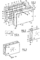
- a cladding panel according to the invention having, for example, dimensions of 600 x 400 mm.
- This panel has two main parts, namely a block 1 of insulating material and a facing 2 made of sheet steel.
- the block of insulating material has a generally parallelepiped shape but, according to the invention, it is shaped so as to delimit along two of its adjacent lateral faces a flange 3 and 4 which is set back with respect to the front face 5 of the block.
- a flange 3 and 4 which is set back with respect to the front face 5 of the block.
- two protruding flanges 6 and 7 are provided along the two other lateral faces of this block.
- the dimensions of the two recessed parts and of the two protruding parts are such that the protruding parts of a panel can come lodge in the recessed parts of another panel.
- this block 1 consists of two parallelepipeds 1a, 1b coming from molding, one of which is offset in translation relative to the other according to a oblique direction with respect to the two perpendicular directions of the sides of this block, for example along the direction of a diagonal of one of the main faces.
- Ventilation channels 8 are provided in the front face 5 of the block of insulating material. oriented, in the example shown, parallel to the sides of this block. These channels open on the one hand into channels formed in the recessed edges 3, 4, and on the other hand at the free edges of the two projecting edges 6 and 7.
- this same front face of the block can open out holes 10 for the passage of fixing members 11, these orifices ending in a rebate 12 of larger diameter making it possible to receive the heads 11a of these fixing members, as shown in phantom in Figure 1.
- holes 13 are provided for the passage of fixing members constituted in the example chosen by nail 14 and insulating plug 15 assemblies.
- the block of insulating material can be made for example of molded polystyrene.
- the metal facing 2 which can be made of prepainted steel, consists of a stamped sheet in the form of an open parallelepiped whose depth corresponds to the thickness of the front part 1b of the insulating block.
- This facing comprises along two of its adjacent lateral faces two flanges 16, 17 arranged exactly opposite the two flanges 3, 4 of the insulating block, and in which are provided fixing holes 18 and ventilation openings 19 arranged opposite channels 9.
- Each metal facing also includes along the lower edge of its lateral face opposite the rim 17, fixing lugs 20 which preferably have a T shape. These fixing lugs engage in corresponding housings 21, 22 provided respectively at the base of the face side of the facing adjacent to the rim 17 and at the base of the front part 5 of the block of insulating material.
- Each panel is fixed to the support wall by means of nails and dowels 14, 15 as shown in FIG. 1, the lower fixing lugs 20 engaging in the corresponding housings 21, 22 of the panel or panels located immediately below . Furthermore, a seal 23 having an L-shape is disposed between the metal facings of adjacent panels.
- the T-shaped legs 20 ensure, by means of their upper horizontal branches 20a, regular spacing between the panels ( Figure 4).
- fixing members are perfectly protected and inaccessible so that the panels cannot be dismantled easily by people who do not have a minimum of tools.
- a saw blade is used which will make it possible to saw the two edges 16 and 17 of the metal facing.
- a guide 30 is used, shown in the Figure 2, which has on its rear side legs 31 engaging in the gap between the panels and which defines a slot 32 for the saw.
- the guide 30 furthermore comprises, at one end of the slot 32, an end-of-travel stop 33. This sawing operation is carried out on the one hand on the vertical edge and on the other hand on the horizontal edge by means of a similar guide, following the line shown in phantom in Figure 1.
- One or more holes 34 are then made in the metal facing to allow the introduction of a tear-off key 35, as shown in FIG. 3.
- the device according to the invention makes it possible to effectively solve the problem posed, and this by particularly simple and economical means, the implementation of which is very easy.
- this panel can easily be adapted according to the desired insulation characteristics by providing panels whose rear parts 1a have more or less thicknesses, the front parts 1b on the other hand having constant thicknesses.
Landscapes
- Engineering & Computer Science (AREA)
- Architecture (AREA)
- Civil Engineering (AREA)
- Structural Engineering (AREA)
- Chemical Kinetics & Catalysis (AREA)
- Mechanical Engineering (AREA)
- Electrochemistry (AREA)
- Chemical & Material Sciences (AREA)
- Finishing Walls (AREA)
- Load-Bearing And Curtain Walls (AREA)
- Building Environments (AREA)
- Chemical And Physical Treatments For Wood And The Like (AREA)
- Laminated Bodies (AREA)
- Glass Compositions (AREA)
Priority Applications (1)
| Application Number | Priority Date | Filing Date | Title |
|---|---|---|---|
| AT84402329T ATE22340T1 (de) | 1983-11-25 | 1984-11-15 | Verkleidungsplatte. |
Applications Claiming Priority (2)
| Application Number | Priority Date | Filing Date | Title |
|---|---|---|---|
| FR8318860 | 1983-11-25 | ||
| FR8318860A FR2555628B1 (fr) | 1983-11-25 | 1983-11-25 | Perfectionnements aux panneaux de veture |
Publications (3)
| Publication Number | Publication Date |
|---|---|
| EP0143696A2 true EP0143696A2 (de) | 1985-06-05 |
| EP0143696A3 EP0143696A3 (de) | 1985-07-10 |
| EP0143696B1 EP0143696B1 (de) | 1986-09-17 |
Family
ID=9294552
Family Applications (1)
| Application Number | Title | Priority Date | Filing Date |
|---|---|---|---|
| EP84402329A Expired EP0143696B1 (de) | 1983-11-25 | 1984-11-15 | Verkleidungsplatte |
Country Status (4)
| Country | Link |
|---|---|
| EP (1) | EP0143696B1 (de) |
| AT (1) | ATE22340T1 (de) |
| DE (1) | DE3460773D1 (de) |
| FR (1) | FR2555628B1 (de) |
Cited By (1)
| Publication number | Priority date | Publication date | Assignee | Title |
|---|---|---|---|---|
| GB2202874A (en) * | 1987-03-18 | 1988-10-05 | Otford E P S Limited | Insulating panels with offset upper & lower faces |
Family Cites Families (3)
| Publication number | Priority date | Publication date | Assignee | Title |
|---|---|---|---|---|
| US1807667A (en) * | 1931-06-02 | Metai | ||
| US3482367A (en) * | 1968-04-12 | 1969-12-09 | Robertson Co H H | Field erected insulated wall structure |
| DE2623355A1 (de) * | 1976-05-25 | 1977-12-08 | Paul Kaiser | Fassadenplatte |
-
1983
- 1983-11-25 FR FR8318860A patent/FR2555628B1/fr not_active Expired
-
1984
- 1984-11-15 DE DE8484402329T patent/DE3460773D1/de not_active Expired
- 1984-11-15 AT AT84402329T patent/ATE22340T1/de not_active IP Right Cessation
- 1984-11-15 EP EP84402329A patent/EP0143696B1/de not_active Expired
Cited By (1)
| Publication number | Priority date | Publication date | Assignee | Title |
|---|---|---|---|---|
| GB2202874A (en) * | 1987-03-18 | 1988-10-05 | Otford E P S Limited | Insulating panels with offset upper & lower faces |
Also Published As
| Publication number | Publication date |
|---|---|
| EP0143696B1 (de) | 1986-09-17 |
| DE3460773D1 (en) | 1986-10-23 |
| ATE22340T1 (de) | 1986-10-15 |
| EP0143696A3 (de) | 1985-07-10 |
| FR2555628B1 (fr) | 1987-05-15 |
| FR2555628A1 (fr) | 1985-05-31 |
Similar Documents
| Publication | Publication Date | Title |
|---|---|---|
| EP0685614A1 (de) | Befestigungsvorrichtung von Verkleidungsplatten | |
| FR2903707A1 (fr) | Element de fixation pour lame de couverture de surface et lame de couverture de surface adaptee a un tel element de fixation | |
| EP2791440B1 (de) | Wärmedämmungssystem mit zwischenlagern zum halten von vip-platten und entsprechendes montageverfahren | |
| EP2746489A1 (de) | Distanzstück zur thermischen und elektrolytischen Unterbrechung für Wandbefestigungswinkel eines Verkleidungspaneels und Verfahren zur Befestigung des Verkleidungspaneels | |
| EP0974706B1 (de) | Verstellbare Trennwand | |
| EP0143696B1 (de) | Verkleidungsplatte | |
| FR3065980B1 (fr) | Systeme d’habillage d’un bord d'ouverture dans une cloison | |
| FR2607171A1 (fr) | Lisse pour revetement de facade et revetement de facade utilisant de telles lisses | |
| FR2878875A1 (fr) | Module pour l'habillage de plafonds et de murs | |
| FR3060623A1 (fr) | Equerre de fixation d'un panneau isolant | |
| EP0931890A1 (de) | Befestigungsklammer und Gerüst mit einer solchen Klammer, z.B. Gerüst zum Befestigen von Isolationselementen auf einem Dach | |
| EP0937857B1 (de) | Feuerbeständige Trennwand mit Verglasungselementen | |
| EP0120788A1 (de) | Zusammensetzung in einer thermischen Aussenisolation | |
| FR2514388A1 (fr) | Cloison murale modulaire | |
| EP0791700A1 (de) | Befestigungshalterung und Abstandhalter zur Erstellung von Verkleidungen im Bausektor, und so hergestellte Verkleidungen | |
| FR2754302A1 (fr) | Dispositif de montage d'un vitrage dans un chassis de support pour porte, fenetre ou analogue | |
| FR2800405A1 (fr) | Cloison a double paroi modulaire transparente | |
| FR2664633A1 (fr) | Plafond suspendu. | |
| EP2501876B1 (de) | Aus einem satz montagefertiger separater teile geformtes geländer | |
| FR3026771A1 (fr) | Procede de pose d'un dormant adapte pour des ouvrants coulissants et dormant integre adapte pour ledit procede de pose | |
| FR2607167A1 (fr) | Profile pour cadre de panneau, en particulier de plafond suspendu, de cloison ou d'habillage mural | |
| WO2012052625A1 (fr) | Bardage métallique à capot sécurisé | |
| FR2689541A1 (fr) | Ensemble de construction pour la réalisation de cloisons amovibles. | |
| FR2739122A1 (fr) | Dispositif pour la finition par recouvrement de la zone de jonction entre deux surfaces contigues, par exemple entre une paroi verticale et un sol, ou entre deux revetements muraux | |
| EP3916168A1 (de) | Abstandhalter für die auskleidung einer wand |
Legal Events
| Date | Code | Title | Description |
|---|---|---|---|
| PUAI | Public reference made under article 153(3) epc to a published international application that has entered the european phase |
Free format text: ORIGINAL CODE: 0009012 |
|
| PUAL | Search report despatched |
Free format text: ORIGINAL CODE: 0009013 |
|
| AK | Designated contracting states |
Designated state(s): AT BE CH DE FR GB IT LI LU NL SE |
|
| AK | Designated contracting states |
Designated state(s): AT BE CH DE FR GB IT LI LU NL SE |
|
| RTI1 | Title (correction) | ||
| 17P | Request for examination filed |
Effective date: 19850629 |
|
| GRAA | (expected) grant |
Free format text: ORIGINAL CODE: 0009210 |
|
| AK | Designated contracting states |
Kind code of ref document: B1 Designated state(s): AT BE CH DE FR GB IT LI LU NL SE |
|
| REF | Corresponds to: |
Ref document number: 22340 Country of ref document: AT Date of ref document: 19861015 Kind code of ref document: T |
|
| ITF | It: translation for a ep patent filed | ||
| REF | Corresponds to: |
Ref document number: 3460773 Country of ref document: DE Date of ref document: 19861023 |
|
| PLBE | No opposition filed within time limit |
Free format text: ORIGINAL CODE: 0009261 |
|
| STAA | Information on the status of an ep patent application or granted ep patent |
Free format text: STATUS: NO OPPOSITION FILED WITHIN TIME LIMIT |
|
| 26N | No opposition filed | ||
| ITTA | It: last paid annual fee | ||
| EPTA | Lu: last paid annual fee | ||
| EAL | Se: european patent in force in sweden |
Ref document number: 84402329.1 |
|
| PGFP | Annual fee paid to national office [announced via postgrant information from national office to epo] |
Ref country code: CH Payment date: 19971016 Year of fee payment: 14 |
|
| PGFP | Annual fee paid to national office [announced via postgrant information from national office to epo] |
Ref country code: DE Payment date: 19971024 Year of fee payment: 14 Ref country code: AT Payment date: 19971024 Year of fee payment: 14 |
|
| PGFP | Annual fee paid to national office [announced via postgrant information from national office to epo] |
Ref country code: NL Payment date: 19971029 Year of fee payment: 14 |
|
| PGFP | Annual fee paid to national office [announced via postgrant information from national office to epo] |
Ref country code: GB Payment date: 19971107 Year of fee payment: 14 |
|
| PGFP | Annual fee paid to national office [announced via postgrant information from national office to epo] |
Ref country code: SE Payment date: 19971124 Year of fee payment: 14 |
|
| PGFP | Annual fee paid to national office [announced via postgrant information from national office to epo] |
Ref country code: FR Payment date: 19971127 Year of fee payment: 14 |
|
| PGFP | Annual fee paid to national office [announced via postgrant information from national office to epo] |
Ref country code: BE Payment date: 19971212 Year of fee payment: 14 |
|
| PGFP | Annual fee paid to national office [announced via postgrant information from national office to epo] |
Ref country code: LU Payment date: 19971215 Year of fee payment: 14 |
|
| PG25 | Lapsed in a contracting state [announced via postgrant information from national office to epo] |
Ref country code: LU Free format text: LAPSE BECAUSE OF NON-PAYMENT OF DUE FEES Effective date: 19981115 Ref country code: GB Free format text: LAPSE BECAUSE OF NON-PAYMENT OF DUE FEES Effective date: 19981115 Ref country code: AT Free format text: LAPSE BECAUSE OF NON-PAYMENT OF DUE FEES Effective date: 19981115 |
|
| PG25 | Lapsed in a contracting state [announced via postgrant information from national office to epo] |
Ref country code: SE Free format text: LAPSE BECAUSE OF NON-PAYMENT OF DUE FEES Effective date: 19981116 |
|
| PG25 | Lapsed in a contracting state [announced via postgrant information from national office to epo] |
Ref country code: LI Free format text: LAPSE BECAUSE OF NON-PAYMENT OF DUE FEES Effective date: 19981130 Ref country code: CH Free format text: LAPSE BECAUSE OF NON-PAYMENT OF DUE FEES Effective date: 19981130 Ref country code: BE Free format text: LAPSE BECAUSE OF NON-PAYMENT OF DUE FEES Effective date: 19981130 |
|
| BERE | Be: lapsed |
Owner name: S.A. DE CONSTRUCTION ET DE GALVANISATION DE MOTAT Effective date: 19981130 |
|
| PG25 | Lapsed in a contracting state [announced via postgrant information from national office to epo] |
Ref country code: NL Free format text: LAPSE BECAUSE OF NON-PAYMENT OF DUE FEES Effective date: 19990601 |
|
| GBPC | Gb: european patent ceased through non-payment of renewal fee |
Effective date: 19981115 |
|
| REG | Reference to a national code |
Ref country code: CH Ref legal event code: PL |
|
| PG25 | Lapsed in a contracting state [announced via postgrant information from national office to epo] |
Ref country code: FR Free format text: LAPSE BECAUSE OF NON-PAYMENT OF DUE FEES Effective date: 19990730 |
|
| EUG | Se: european patent has lapsed |
Ref document number: 84402329.1 |
|
| NLV4 | Nl: lapsed or anulled due to non-payment of the annual fee |
Effective date: 19990601 |
|
| REG | Reference to a national code |
Ref country code: FR Ref legal event code: ST |
|
| PG25 | Lapsed in a contracting state [announced via postgrant information from national office to epo] |
Ref country code: DE Free format text: LAPSE BECAUSE OF NON-PAYMENT OF DUE FEES Effective date: 19990901 |