EP0143930A2 - Procédé de fabrication de brosses et machine pour la mise en oeuvre du procédé - Google Patents
Procédé de fabrication de brosses et machine pour la mise en oeuvre du procédé Download PDFInfo
- Publication number
- EP0143930A2 EP0143930A2 EP84111396A EP84111396A EP0143930A2 EP 0143930 A2 EP0143930 A2 EP 0143930A2 EP 84111396 A EP84111396 A EP 84111396A EP 84111396 A EP84111396 A EP 84111396A EP 0143930 A2 EP0143930 A2 EP 0143930A2
- Authority
- EP
- European Patent Office
- Prior art keywords
- bristle
- bundle
- gripper
- machine according
- separating device
- Prior art date
- Legal status (The legal status is an assumption and is not a legal conclusion. Google has not performed a legal analysis and makes no representation as to the accuracy of the status listed.)
- Granted
Links
- 238000004519 manufacturing process Methods 0.000 title claims abstract description 10
- 238000000034 method Methods 0.000 title claims description 7
- 238000004806 packaging method and process Methods 0.000 claims description 4
- 238000012546 transfer Methods 0.000 claims description 3
- 238000000926 separation method Methods 0.000 description 9
- 230000032258 transport Effects 0.000 description 6
- 230000000903 blocking effect Effects 0.000 description 2
- 238000013461 design Methods 0.000 description 2
- 238000006073 displacement reaction Methods 0.000 description 2
- 230000007257 malfunction Effects 0.000 description 2
- 239000000463 material Substances 0.000 description 2
- 238000012545 processing Methods 0.000 description 2
- 230000000284 resting effect Effects 0.000 description 2
- 230000006978 adaptation Effects 0.000 description 1
- 239000003086 colorant Substances 0.000 description 1
- 238000011161 development Methods 0.000 description 1
- 238000002474 experimental method Methods 0.000 description 1
Images


Classifications
-
- A—HUMAN NECESSITIES
- A46—BRUSHWARE
- A46D—MANUFACTURE OF BRUSHES
- A46D3/00—Preparing, i.e. Manufacturing brush bodies
- A46D3/08—Parts of brush-making machines
- A46D3/082—Magazines for bristles; Feeding bristles to magazines; Knot picking
Definitions
- the invention relates to a method for producing brushes, in which bristle bundles enclosed by a covering, packaging or the like are brought into the vicinity of a bristle supply and are there fed to the bristle supply after removal of their packaging, covering or the like.
- a knife for separating the sheathing.
- Such a knife can be guided radially and / or in the longitudinal direction through the casing.
- the disadvantages here are that damage to the bristles cannot be ruled out by the knife and that the bristles can also be pushed out of the bristle supply by the knife, which can lead to malfunctions.
- such knives become dull over time and have to be replaced.
- there is also the fact that such a blunt knife can also cause malfunctions.
- additional devices are required to remove the separated coverings, so that a total of one increased effort is given.
- the object of the present invention is to provide a method of the type mentioned at the outset, by means of which a trouble-free separation of sheaths from the bristles therein is possible even over a longer period.
- the coated bristle bundle is grasped on its covering and this is removed in sections, after which the exposed bundle section is gripped and the bristle bundle and the covering are separated from one another.
- the bundle of bristles is held alternately, preferably overlapping in time, when the sheath is removed. As a result, the bundle of bristles is held securely during the entire separation process.
- the invention also relates to a brush production machine with a device for supplying bristles to a tamping device or the like, a separating device for removing an envelope or the like initially encasing the individual bristle bundles and a subsequent transfer device for the bristles or the bristle supply are provided.
- Such a brush manufacturing machine is according to the invention in particular characterized in that the Separating device has a gripping device with at least one holding and pulling-off gripper for gripping the covered bristle bundle and for at least partially pulling off the covering and at least one removal gripper or the like for gripping the free bundle section and for removing or transporting the bundle.
- the covering is pulled off somewhat in some areas and the bundle, which is then partially exposed, is gripped by the removal gripper and pulled out of the covering. Mechanical removal of the casing is achieved. Because there are practically no wearing parts, such a separating device is also largely maintenance-free.
- the grippers expediently each have at least two gripping jaws or the like which can be moved approximately radially to the bristle bundle, with gripping surfaces which are approximately matched to the outline shape of the bristle bundle, in particular approximately semicircular.
- the bundle of bristles is thereby tightly encompassed during the separation process and also for further transport, so that the bundle of bristles is held together without a covering.
- the holding and pulling gripper can be displaced in relation to the bristle bundle in the longitudinal direction thereof by part of the bundle length.
- the covering can thereby be gripped and pulled back somewhat by the displacement movement, so that one end of the bristle bundle becomes free.
- the removal gripper is expediently also approximately coaxial to the bristle bundle and additionally preferably transversely thereto, e.g. B. to a bristle magazine, movable.
- the removal gripper can grip the exposed bristle bundle and then pull it out of the casing and, if necessary, towards a bristle magazine or the like move.
- the bristle bundles are mounted approximately vertically in the region of the separating device, the gripping and pulling gripper engaging at the upper end or the removal gripper being arranged such that it can be fed from above. In this vertical position, the covering can be pulled off, a support for the bristles being formed on the underside by the support.
- a pressure application device is provided in the bristle magazine, which has pressure elements acting alternately on the bristle supply, the greatest distance between these pressure elements corresponding at least approximately to the cross-section of a bundle of bristles supplied by the removal gripper. The bristle bundles separated from the covering can thus be introduced into the bristle stock without the bristle stock already in the magazine having to be changed, in particular with regard to the pressurization.
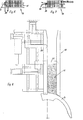
- a separating device 1 shown in FIG. 1 is part of a brush manufacturing machine, in which in particular bristles 3 initially located in a covering 2 are fed to a brush tamping machine, of which only the so-called circular arc divider 4 can be seen in FIGS. 1, 8 and 11.
- the separating device 1 essentially has a gripping device designated as 5.
- a holding and pulling gripper 6 is provided for gripping the covered bristle bundle 8, as shown in FIG. 1, and also for at least partially pulling off the covering 2, as can be seen in FIG. 2.
- the gripping device 5 also has a removal gripper 7, with which the free bundle section 9 can be gripped and pulled out of the casing 2.
- the bristle bundle 8 pulled out of the casing 2 is transported with the aid of the removal gripper 7 to a bristle supply 11 located in a magazine 10.
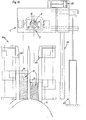
- the grippers 6 and 7 each have two gripping jaws 12, 13 in the exemplary embodiment, which have approximately adapted to the outline shape of the bristle bundle 8, in particular approximately semicircular gripping surfaces 14, as can be clearly seen in FIGS. 9 to 11.
- the holding and pulling gripper 6 is accommodated in a lifting frame 15, which overall can be displaced in height relative to the bristle bundle 8 located in the separating device 1 according to the arrow Pf 1.
- Pneumatic lifting drives 16 in particular are provided both for adjusting the gripping jaws 12 and 13 and for adjusting the height of the lifting frame 15.
- a bristle bundle 8 located in the separating device 1 is vertically open with respect to its longitudinal extent a support 17 is mounted, which in the exemplary embodiment is part of the bottom of a feed device 18 (cf. FIGS. 9 and 10).
- the sheathing 2 is now separated from a bundle of bristles 8 in that the coated bundle of bristles 8 is first gripped by the gripping jaws 12 of the holding and pulling gripper 6 at the upper end region, as can be clearly seen in FIG. 1.
- the lifting drive 16 for the lifting frame 15 By actuating the lifting drive 16 for the lifting frame 15, the holding and pulling gripper 6 is moved somewhat downward relative to the bristle bundle 8, the covering 2 being correspondingly stripped off.
- the lifting movement is dimensioned such that the upper bundle section 9, which is free of the covering 2, grips the removal gripper securely
- the lifting movement of the holding and pulling-off gripper 6 could be provided such that the covering 2 is stripped off over approximately half the bristle length.
- the removal gripper 7 in its up position in FIG. 1 is then moved to the bristle bundle 8 until its gripping jaws 13 are located to the side of the free bundle section 9. Then the bristle bundle 8 is gripped at its free bundle section 9 by closing the gripping jaws 13 (see FIG. 2) and pulled out of the casing 2 by raising the removal gripper 7.
- the holding and pulling gripper 6 remains approximately in its closed position during this separation process, but its gripping jaws 12 can yield somewhat radially, which can be achieved by removing the pressure from the lifting cylinders 16.
- the covering 2 is thus stripped off on the gripping jaws 12 without a greater pull-out resistance being present.
- the bristle bundle 8 is held alternately, preferably overlapping in time, by the grippers 6 and 7, so that the bristle bundle 8 is held securely in each phase of the separation.
- the removal gripper 7 is also horizontally displaceable, the horizontal guide 19 leading to the magazine 10 in the exemplary embodiment.
- a bristle bundle held by the gripping jaws 13 can thereby be transported laterally from the area of the separating device 1 into the area of the magazine 10.
- the bristle magazine 10 has a pressurizing device with pressure elements 20, 21 which act alternately on the bristle supply 11. This causes an approximately constant supply pressure to the circular arc divider 4.
- the bristle bundle 8 is inserted into the magazine 10 between these pressure elements 20, 21, as is shown in FIG. 4. After the bristle bundle 8 has been deposited, it is acted upon and held on the back by the fork-shaped pressure element 20 (FIG. 5). Subsequently, as shown in FIG.
- the finger-shaped pressure element 21 can be pulled out of the bristle supply and then takes over the loading of the bristle supply instead of the fork-shaped pressure element 20.
- the fork-shaped pressure element 20 can then be moved back to a position (FIGS. 7 and 1) until the space between the pressure elements 20 and 21 is sufficient to accommodate the next bundle of bristles 8 separated from the sheath 2.
- FIG. 8 shows a top view of the arrangement of the pressure elements 20, 21 in the magazine 10, the discharge end of which opens in the region of the circular-arc compartment 4. It can also be clearly seen here that the pressure elements 20, 21 can be displaced both in the longitudinal direction of the magazine 10 and in the disengagement and engagement position.
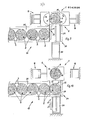
- Fig. 11 shows a separation device 1 in supervision with an associated double magazine 10 a, in which, for example, bristles with different colors are entered.
- the removal gripper 7 is arranged so as to be displaceable transversely to the longitudinal extent of the magazine 10 a in accordance with the distance between these magazine channels.
- the lifting cylinder 22 is provided as the drive, while a further lifting cylinder 23 is provided for moving the removal gripper 7 from the separating device to the magazine 10 a.
- the holding and pulling gripper 6 lying below the removal gripper 7 is not visible in this illustration.
- the feed device shown in FIGS. 9 and 10 serves to feed the coated or coated bristle bundles 8 to the separating device 1. It has a separating device 24 with a combined blocking and transport slide 25 at its feed end. With the separating device 24, the bristle bundles 8 arriving one after the other via a guide channel 26 can be fed one after the other to the separating device 1.
- the locking and transport slide 25 is approximately angular in shape with a locking side 27 and a feed side 28. If the slide 25 is in the release position shown in FIG. 9, the bristle bundles located in the guide channel 26, which preferably runs at an angle, can slip, the foremost one resting against a stop 29.
- the slide 25 By moving the slide 25 transversely, for which a lifting cylinder 30 is provided here, the slide 25 moves into the blocking position shown in FIG. 8, whereby it transports the bundle of bristles 8 resting against the stop 29 into the separating device 1. After the slide has been pulled back, the gripping jaws 12 of the holding and pulling-off gripper 6 shown here can grip the bristle bundle 8 or its sheath 2.
- the stripped sheath 2 could be removed by compressed air.
- the magazines 10, 10 a often have comparatively narrow receiving channels for the bristle supply 11, the width of these channels being smaller than the diameter of the approximately round bristle bundles 8.
- the bristle bundles are adapted to the shape of the bristle receptacle, in particular to the width of the magazine receptacle channels, during and / or after removal of the sheath 2.
- the clear receiving cross-section of the gripping jaws 13 of the removal gripper 7 in the closed position z. B. be rectangular, the narrow sides at most corresponding to the width of a magazine receiving channel.
- the bristle bundle 8 could also be gradually deformed from its round cross-sectional shape into a cross-sectional shape suitable for a subsequent magazine.
- the receiving cross section of the gripping jaws 12 of the holding and pulling gripper 6 can already have an intermediate shape between the round cross section and the intended delivery cross section of the bristle bundle, and the receiving cross section of the removal gripper jaws 13 can correspond to the final, intended delivery cross section of the bristle bundles 8.
- the separating borehole direction 1 can also be designed for horizontal storage of the bristle bundles 8, preferably with a one-sided, end-face stop.
- the design with gripping jaws fixed on one side is also particularly advantageous. It should also be mentioned that the gripping jaws 12 are fixed in the pulling direction and the end stop or the base 17 can be movable relative to it for the partial removal of the casing 2.
- the separating device 1 according to the invention can also be used separately without a feed connection to a bristle storage magazine or, if appropriate, in connection with a material dressing device.
- the separating device 1 according to the invention also in connection with the respectively adjacent devices 18 and 10, has the essential advantage that the transport, the respective transfers and the separation of the casing 2 with comparatively simple means and at the same time high operational reliability even over longer production sections without problems can expire. This is also a prerequisite for the planned, largely largely automatic overall production process.
- a double magazine 10 a (Fig.
- associated separating device 1 is expediently also provided a double feed device 18 a for bristle bundles 8, as shown in FIG. 12.
- bristle bundles 8 containing alternating or optionally different bristles can be fed to the separating device 1.
- the bristles held by the removal gripper 7 are fed to one of the magazine channels 31 or 31 a, depending on the type.
- the bristles can e.g. B. differ in terms of color, bristle length, thickness, material, etc.
- the feed device 18 a and the magazine are designed for two different types of bristles. If necessary, these devices could also be set up for more than two types of bristle. Despite this processing of several types of bristle, it is advantageous to use only one separating device 1. The mechanical effort is therefore comparatively low overall even when processing several different types of bristle.
- two feed channels 32 coming from bristle bundle magazines can be seen which are connected to the separating device 24.
- the feed channels 32 and the connecting channel 34 can be arranged obliquely as slides.
Landscapes
- Engineering & Computer Science (AREA)
- Manufacturing & Machinery (AREA)
- Brushes (AREA)
Applications Claiming Priority (6)
| Application Number | Priority Date | Filing Date | Title |
|---|---|---|---|
| DE3343071 | 1983-11-29 | ||
| DE19838334183 DE8334183U1 (de) | 1983-11-29 | 1983-11-29 | Buerstenherstellungsmaschine mit einer Borstenzufuehreinrichtung |
| DE8334183U | 1983-11-29 | ||
| DE3343071 | 1983-11-29 | ||
| DE3402050 | 1984-01-21 | ||
| DE19843402050 DE3402050A1 (de) | 1983-11-29 | 1984-01-21 | Verfahren zum herstellen von buersten sowie buerstenherstellungsmaschine zur durchfuehrung des verfahrens |
Publications (3)
| Publication Number | Publication Date |
|---|---|
| EP0143930A2 true EP0143930A2 (fr) | 1985-06-12 |
| EP0143930A3 EP0143930A3 (en) | 1986-05-14 |
| EP0143930B1 EP0143930B1 (fr) | 1989-03-22 |
Family
ID=27191464
Family Applications (1)
| Application Number | Title | Priority Date | Filing Date |
|---|---|---|---|
| EP84111396A Expired EP0143930B1 (fr) | 1983-11-29 | 1984-09-25 | Procédé de fabrication de brosses et machine pour la mise en oeuvre du procédé |
Country Status (3)
| Country | Link |
|---|---|
| US (1) | US4647113A (fr) |
| EP (1) | EP0143930B1 (fr) |
| DE (1) | DE3477345D1 (fr) |
Cited By (3)
| Publication number | Priority date | Publication date | Assignee | Title |
|---|---|---|---|---|
| EP0184866A1 (fr) * | 1984-11-08 | 1986-06-18 | G.B. Boucherie, N.V. | Dispositif d'alimentation automatique des magasins et/ou cassettes de soies pour machines à fabriquer des brosses |
| EP0193220A1 (fr) * | 1985-02-26 | 1986-09-03 | G.B. Boucherie, N.V. | Procédé pour retirer l'enveloppe d'un paquet de soies et dispositif pour la mise en oeuvre dudit procédé |
| WO2020169420A1 (fr) * | 2019-02-20 | 2020-08-27 | Gb Boucherie Nv | Procédé de remplissage d'une boîte à fibres et séparateur de paquets |
Families Citing this family (9)
| Publication number | Priority date | Publication date | Assignee | Title |
|---|---|---|---|---|
| BE1000367A4 (nl) * | 1987-03-06 | 1988-11-08 | Boucherie Nv G B | Werkwijze voor het toevoeren van vezels aan borstelvervaardigingsmachines en inrichting die deze werkwijze toepast. |
| DE3735329C2 (de) * | 1987-10-19 | 1998-04-16 | Zahoransky Anton Gmbh & Co | Verfahren zum Herstellen von Bürsten aus losem und ungebündeltem Material sowie Bürstenherstellungsmaschine zur Durchführung des Verfahrens |
| DE59007034D1 (de) * | 1989-06-24 | 1994-10-13 | Frisetta Gmbh | Verfahren und Vorrichtung zum Herstellen von Borstenfeldern oder Borstenbündeln. |
| FR2701198B1 (fr) | 1993-02-08 | 1995-04-21 | Oreal | Brosse de maquillage et procédé de fabrication d'une telle brosse. |
| US5927819A (en) * | 1997-02-28 | 1999-07-27 | Gillette Canada Inc. | Method and device for trimming and end-rounding bristles |
| DE10149043C1 (de) * | 2001-10-05 | 2003-03-20 | Rueb F A Holding Gmbh | Verfahren und Vorrichtung zum Herstellen von Bürsten, insbesondere Zahnbürsten |
| US10646031B2 (en) * | 2016-04-08 | 2020-05-12 | M+C Schiffer Gmbh | Feeding device for feeding batches of bristle filaments to a bristle filament cassette |
| EP3351142B1 (fr) * | 2017-01-24 | 2019-10-16 | The Procter and Gamble Company | Dispositif de ramassage de touffes destiné à une machine de fabrication de brosse |
| CN110934416A (zh) * | 2019-11-28 | 2020-03-31 | 安徽省潜山县志发机电配件有限公司 | 一种工业刷生产用刷丝匝束设备 |
Family Cites Families (9)
| Publication number | Priority date | Publication date | Assignee | Title |
|---|---|---|---|---|
| US1810645A (en) * | 1927-10-15 | 1931-06-16 | Bliss E W Co | Intermittent feed mechanism |
| US2356121A (en) * | 1941-07-22 | 1944-08-15 | Fuller Brush Co | Bristle feeding mechanism for brushmaking machines |
| US2893594A (en) * | 1956-02-07 | 1959-07-07 | Continental Can Co | Bulk storage of cans for delivery to an operating unit |
| SE360617B (fr) * | 1972-03-13 | 1973-10-01 | Platmanufaktur Ab | |
| DE2632328C2 (de) * | 1976-07-17 | 1986-08-28 | Zahoransky, Anton, 7868 Todtnau | Verfahren zum Herstellen von Bürsten sowie Bürstenherstellungsmaschine zur Durchführung des Verfahrens |
| DE2643222A1 (de) * | 1976-09-25 | 1978-04-06 | Zahoransky Anton Fa | Buerstenherstellungsmaschine sowie verfahren zur buerstenherstellung |
| FR2423403A1 (fr) * | 1978-04-19 | 1979-11-16 | Emballage Ste Gle Pour | Procede et dispositif de deballage d'objets |
| US4390313A (en) * | 1980-03-27 | 1983-06-28 | Hoehn John Walter | Method and apparatus for depacking articles |
| DE3402051A1 (de) * | 1984-01-21 | 1985-07-25 | Fa. Anton Zahoransky, 7868 Todtnau | Buerstenherstellungsmaschine mit einer zufuehrvorrichtung |
-
1984
- 1984-09-25 EP EP84111396A patent/EP0143930B1/fr not_active Expired
- 1984-09-25 DE DE8484111396T patent/DE3477345D1/de not_active Expired
-
1986
- 1986-02-04 US US06/826,063 patent/US4647113A/en not_active Expired - Lifetime
Cited By (3)
| Publication number | Priority date | Publication date | Assignee | Title |
|---|---|---|---|---|
| EP0184866A1 (fr) * | 1984-11-08 | 1986-06-18 | G.B. Boucherie, N.V. | Dispositif d'alimentation automatique des magasins et/ou cassettes de soies pour machines à fabriquer des brosses |
| EP0193220A1 (fr) * | 1985-02-26 | 1986-09-03 | G.B. Boucherie, N.V. | Procédé pour retirer l'enveloppe d'un paquet de soies et dispositif pour la mise en oeuvre dudit procédé |
| WO2020169420A1 (fr) * | 2019-02-20 | 2020-08-27 | Gb Boucherie Nv | Procédé de remplissage d'une boîte à fibres et séparateur de paquets |
Also Published As
| Publication number | Publication date |
|---|---|
| EP0143930A3 (en) | 1986-05-14 |
| US4647113A (en) | 1987-03-03 |
| EP0143930B1 (fr) | 1989-03-22 |
| DE3477345D1 (en) | 1989-04-27 |
Similar Documents
| Publication | Publication Date | Title |
|---|---|---|
| DE2918687C2 (fr) | ||
| DE2918725C2 (fr) | ||
| EP1071344A1 (fr) | Appareil de confection personnelle de cigarettes et composants dudit appareil | |
| DE2632328C2 (de) | Verfahren zum Herstellen von Bürsten sowie Bürstenherstellungsmaschine zur Durchführung des Verfahrens | |
| DE69718555T2 (de) | Vorrichtung zum Stapeln von Blättern, insbesondere Geldscheinen, und zum Übertragen der Stapel | |
| EP0143930B1 (fr) | Procédé de fabrication de brosses et machine pour la mise en oeuvre du procédé | |
| DE3406873C2 (de) | Verfahren und Einrichtung zur Herstellung des Panzers eines Lamellenstores | |
| EP0084620A2 (fr) | Appareil pour cercler des balles | |
| DE2849510A1 (de) | Buerstenherstellungsmaschine sowie verfahren zum herstellen von buersten | |
| DE1477011B1 (de) | Vorrichtung zum Herstellen von Gliedluecken bei Reissverschluessen mit fortlaufender Gliederreihe | |
| EP0305956A2 (fr) | Dispositif pour emballer des barres cylindriques composées d'une pluralité de pièces discoides | |
| CH680933A5 (fr) | ||
| DE2051354C3 (de) | Vorrichtung zum Zuführen von Längsdrähten zu Gitterschweißmaschinen | |
| AT523802B1 (de) | Mattenschweißanlage zur Herstellung von Betonstahlmatten | |
| DE3402050A1 (de) | Verfahren zum herstellen von buersten sowie buerstenherstellungsmaschine zur durchfuehrung des verfahrens | |
| EP0150443B1 (fr) | Machine pour la fabrication de brosses munie d'un dispositif d'alimentation | |
| DE2643222C2 (fr) | ||
| AT414234B (de) | Verfahren und vorrichtung zum herauslösen und vereinzeln von abgelängten, magnetisierbaren stahldrähten aus einem drahtvorrat | |
| AT406454B (de) | Vorrichtung zum abbinden von mehreren, im wesentlichen übereinanderliegenden gegenständen | |
| DE3508354C2 (de) | Maschine zum Aufquetschbestücken von Kabeladerenden mit Aderendhülsen od.dgl. Anschlußelementen | |
| DE8334183U1 (de) | Buerstenherstellungsmaschine mit einer Borstenzufuehreinrichtung | |
| DE1817815B2 (de) | Vorrichtung zum Ausrichten von Randlochungen eines Blätterpacks. Ausscheidung aus: 1801965 | |
| DE1757881A1 (de) | Automatische Fuellvorrichtung fuer Zigaretten od.dgl. | |
| DE3406636C2 (fr) | ||
| DE3821904B4 (de) | Verfahren und Vorrichtung zum Herstellen von Blöcken mit Drahtkammbindung |
Legal Events
| Date | Code | Title | Description |
|---|---|---|---|
| PUAI | Public reference made under article 153(3) epc to a published international application that has entered the european phase |
Free format text: ORIGINAL CODE: 0009012 |
|
| AK | Designated contracting states |
Designated state(s): BE DE GB IT |
|
| PUAL | Search report despatched |
Free format text: ORIGINAL CODE: 0009013 |
|
| AK | Designated contracting states |
Kind code of ref document: A3 Designated state(s): BE DE GB IT |
|
| 17P | Request for examination filed |
Effective date: 19860520 |
|
| 17Q | First examination report despatched |
Effective date: 19870814 |
|
| GRAA | (expected) grant |
Free format text: ORIGINAL CODE: 0009210 |
|
| AK | Designated contracting states |
Kind code of ref document: B1 Designated state(s): BE DE GB IT |
|
| ITF | It: translation for a ep patent filed | ||
| REF | Corresponds to: |
Ref document number: 3477345 Country of ref document: DE Date of ref document: 19890427 |
|
| GBT | Gb: translation of ep patent filed (gb section 77(6)(a)/1977) | ||
| PLBE | No opposition filed within time limit |
Free format text: ORIGINAL CODE: 0009261 |
|
| STAA | Information on the status of an ep patent application or granted ep patent |
Free format text: STATUS: NO OPPOSITION FILED WITHIN TIME LIMIT |
|
| 26N | No opposition filed | ||
| PGFP | Annual fee paid to national office [announced via postgrant information from national office to epo] |
Ref country code: GB Payment date: 19900907 Year of fee payment: 7 |
|
| PG25 | Lapsed in a contracting state [announced via postgrant information from national office to epo] |
Ref country code: GB Effective date: 19910925 |
|
| ITTA | It: last paid annual fee | ||
| GBPC | Gb: european patent ceased through non-payment of renewal fee | ||
| PGFP | Annual fee paid to national office [announced via postgrant information from national office to epo] |
Ref country code: BE Payment date: 19931105 Year of fee payment: 10 |
|
| PG25 | Lapsed in a contracting state [announced via postgrant information from national office to epo] |
Ref country code: BE Effective date: 19940930 |
|
| BERE | Be: lapsed |
Owner name: FIRMA ANTON ZAHORANSKY Effective date: 19940930 |
|
| PGFP | Annual fee paid to national office [announced via postgrant information from national office to epo] |
Ref country code: DE Payment date: 20020823 Year of fee payment: 19 |
|
| PG25 | Lapsed in a contracting state [announced via postgrant information from national office to epo] |
Ref country code: DE Free format text: LAPSE BECAUSE OF NON-PAYMENT OF DUE FEES Effective date: 20040401 |