EP0144183A2 - Mechanismus und System zum Halten und Positionieren eines Werkstücks - Google Patents
Mechanismus und System zum Halten und Positionieren eines Werkstücks Download PDFInfo
- Publication number
- EP0144183A2 EP0144183A2 EP84307944A EP84307944A EP0144183A2 EP 0144183 A2 EP0144183 A2 EP 0144183A2 EP 84307944 A EP84307944 A EP 84307944A EP 84307944 A EP84307944 A EP 84307944A EP 0144183 A2 EP0144183 A2 EP 0144183A2
- Authority
- EP
- European Patent Office
- Prior art keywords
- workpiece
- atmospheric
- workpiece positioning
- grippers
- positioning mechanism
- Prior art date
- Legal status (The legal status is an assumption and is not a legal conclusion. Google has not performed a legal analysis and makes no representation as to the accuracy of the status listed.)
- Withdrawn
Links
Images


Classifications
-
- H—ELECTRICITY
- H10—SEMICONDUCTOR DEVICES; ELECTRIC SOLID-STATE DEVICES NOT OTHERWISE PROVIDED FOR
- H10P—GENERIC PROCESSES OR APPARATUS FOR THE MANUFACTURE OR TREATMENT OF DEVICES COVERED BY CLASS H10
- H10P72/00—Handling or holding of wafers, substrates or devices during manufacture or treatment thereof
Definitions
- This invention relates to a mechanism for grasping and releasing workpieces in a manner that prevents accidental damage to the workpieces. It further relates to a mechanism and system for moving workpieces from one location to another during manufacturing. It further relates to such a mechanism and system which are especially adapted for use in moving semiconductor wafers and similar articles which are prone to damage by contamination and which have a relatively high value before manufacturing is completed.
- Any mechanisms used for this purpose must themselves not be a source of significant contamination to the environment in which the integrated circuit manufacturing takes place, and it must be capable of picking up wafer boats at one location, moving them to another location, and releasing them, all in a very reliable manner without damaging the valuable product being manipulated.
- a workpiece holding mechanism in accordance with this invention includes a pair of opposing grippers movable from an open position laterally to a closed position engaging the workpiece.
- a locking means is movable between a first position to lock the grippers in the closed position and a second position to lock the grippers in the open position.
- An actuating means moves the locking means between the first position and the second position.
- a biasing means in opposition to the actuating means urges the locking means toward the first position.
- a means responsive to upward force imparted by the workpiece engaged by the grippers moves the grippers to the open position.
- a workpiece positioning mechanism in accordance with the invention includes such a workpiece holder and an arm having a plurality of joints for moving the workpiece holder.
- the joints preferably include a flexible bellows surrounding each of the joints, so that grease or metal particles from the joints do not contaminate semiconductor wafers or other workpieces prone to damage by contamination when they are being moved.
- the workpiece positioning mechanism also may include a movable base carrying the holding mechanism and the arm.
- a lead screw is connected to move the movable base. Contamination from the lead screw is also prevented by providing a flexible bellows surrounding the lead screw.
- the flexible bellows desirably form part of at least one sealed chamber around the joints, lead screw, and/or other moving parts of the mechanism.
- a pressure different than atmospheric is maintained in the sealed chamber.
- a pressure sensing and indicating means detects a change in the pressure different than atmospheric and thus signals any leaks in the sealed chamber.
- the mechanism 10 includes an arm 12, having a plurality of movable joints 14.
- a rubber, plastic or similar flexible bellows 22 surrounds each of the joints 14.
- the bellows 22 are connected to polypropylene tubing 24, to form a sealed chamber around the moving parts of the arm 12.
- a pair of grippers 26 and 28 are attached to the arm 12.
- a solenoid 30 allows the grippers to move between the closed position shown and open position 32 indicated in dotted line when actuated.
- the arm 12 is connected to a base 40, which is movable by means of lead screw 42 in a direction perpendicular to the plane of Figure 1. Further details of the base 40 and lead screw 42 are shown in Figure 5.
- the positioning mechanism 10 grasps a wafer boat 44 in transfer station 46 and inserts it in a processing solution 48 in tank 50 for carrying out etching or other process operations on a plurality of semiconductor wafers 52 contained in the wafer boat 44.
- the wafer boat 44 is then released by the grippers 26 and 28 during processing, to allow the mechanism 10 to position another wafer boat 44.
- arm 12 is moved to the position shown for moving the wafer boat 44 from tank 50 to a second processing solution 54, for example, a rinse solution, in a second tank 56.
- the wafer boat 44 may be returned by the mechanism 10 to transfer station 46 for further operations.
- the mechanism 10 can also be used to agitate the wafers 52, by oscillating them up and down and/or horizontally. Such motion when the wafers are in a bath 48 or 54 will improve the action of the bath solution.
- each of the joints 14 include pivot plates 16 and pivots 18.
- Rods 20 extend between the joints 14. Through application of suitable actuating forces to the rods 20, arm is moved to position the wafer boat 44 as desired during the operation of the mechanism 10.
- Solenoid 30 is connected to a movable stop 62 positioned between pivotable lever members 64 and 66 by rod 68 within tubing 24.
- portion 70 of stop prevents the pivotable lever members 64 and 66 from pivoting toward one another above pivots 72, thus locking the grippers 26 and 28 in their closed position gripping wafer boat 44 by a lip 74 extending around its top.
- Spring 76 biases rod 68 upwards in opposition to the solenoid 30, to the position shown in Figure 3.
- Member 78 rests on top of lip 74 of the wafer boat 44 when the wafer boat 44 is grasped by grippers 26 and 28.
- a camming member 80 is supported on the member 78.
- a spring 82 is connected between lever members 64 and 66 to bias the camming member 80 downward. With the camming member 80 in the position shown in Figure 3, lever member 64 and 66 are free to assume the position shown in Figure 3, thus closing the grippers 26 and 28 to hold the wafer boat 44.
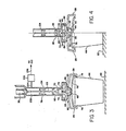
- Figure 4 shows how the grippers 26 and 28 are moved to their open position.
- Solenoid 30 is actuated to lower the stop member 62, so that the pivotable lever members 64 and 66 may pivot their upper ends toward one another.
- Camming member 80 pushes against surfaces 84 to produce the pivoting action, moving grippers 26 and 28 away from wafer boat 44 to the open position shown. This allows upper ends 86 of the stop member 62 to clear the ends 88 of lever members 64 and 66 to engage them from their sides, so that the grippers 26 and 28 are locked in their open position as shown.
- Arm 12 (Figure 1 may now be raised to move the grippers 26 and 28 away from the wafer boat 44.
- the grippers 26 and 28 may also be opened with no wafer boat in place by actuating solenoid 30 to move stop 62 downward to move portion 70 of stop 62.
- spring 82 biases camming member 80 against surfaces 90 of lever members 64 and 66 to produce the pivoting action for moving grippers 26 and 28 to the open position.
- ends 86 of the stop member 62 will clear ends 88 of the lever members 64 and 66 to engage them from their sides.
- grippers 26 and 28 remain in the open position, due to the action of camming member 80 and spring 82 on surfaces 90.
- solenoid 30 In order for grippers 26 and 28 to be closed, solenoid 30 must be turned off and a wafer boat 44 must be in position to push camming member 80 away from surfaces 90. The weight of grippers 26 and 28 then pivots members 64 and 66 to the position shown in Figure 3. Rubber or other flexible material diaphragm 92 is fastened to tubing 24 to form a sealed chamber for preventing the actuating mechanism of Figures 3 and 4 from contaminating the wafers 52 in wafer boat 44.
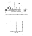
- Figure 5 ' shows the base 40 to which arm 12 is attached.
- the base 40 is movable to the left and right by means of the lead screw 42 attached to the base 40.
- a flexible bellows 94 surrounds the lead screw 42 to prevent contamination of wafers 52 in the wafer boat 44 ( Figure 1) from the lead screw 42.
- Bellows 94 flexes as the base 40 moves laterally.
- a second, different shaped base 40a, a second lead screw 42b and bellows 94b also shown.
- the lead screw 42b and bellows 94b overlaps the first lead screw 42 and bellows 94, so that the path of travel of base 40a may overlap the path of travel of base 40. This allows transfer of a wafer boat 44 between mechanisms 10 located side by side.
- a portion of a third lead screw 42c and bellows 94c connected to a base (not shown) having the same shape as base 40.
- bases 40 and 40a allows a substantial number of the mechanisms 10 to be positioned side by side in a semiconductor wet processing line for carrying out sequential wet processing operations on wafers 52 in wafer boats 44 as they are passed along the line from mechanism 10 to mechanism 10.
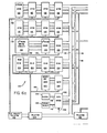
- FIGS 6a and 6b which may be placed together as shown in Figure 6, show a control system 100 for the workpiece gripping and positioning mechanism 10 shown in Figures 1-5.
- a 6502 type microprocessor integrated circuit 102 serves as the central processing unit (CPU) of the system.
- a clock circuit 104 and a timing reset circuit 106 are connected to the CPU 102 by lines 108 and 110, respectively.
- the CPU 102 is connected to 2732 type electrically programmable read only memory (EPROM) circuits 112 by an address bus 114, a data bus 116, and a control bus 118.
- EPROM electrically programmable read only memory
- the busses 114, 116, and 118 also connect the CPU 102 to 2832 type electrically erasable programmable read only memory (E 2 PROM) circuits 120 and E 2 PROM write circuit 122.
- Random access memory (RAM) circuits 124 of the 2114 type are also connected to the CPU 102 by busses 114, 116, and 118.
- Two 1855 type multiply and divide circuits 126 are connected to the CPU 102 by busses 114 and 116.
- a 74LS138 type chip select circuit 128 is connected to the EPROM circuits 112 by lines 130 and 132.
- a second chip select circuit 134 is connected to the E 2 PROM circuits 120, the E 2 PROM write circuit 122, the RAM circuits 124 and the multiply and divide circuits 126 by lines 136, 138, 140 and 142, respectively.
- the chip select circuits 128 and 134 are also connected to the CPU 102 by bus 114.
- Busses 114, 116 and 118 also connect the CPU 102 to a 6582 type input/output (I/O) circuit 150.
- the I/O circuit 150 is connected to a start and emergency off switch 152 by line 154.
- Busses 156 and 158 connect the I/O circuit 150 to RS232C type ports 160 and 162.
- the RS232C port 160 is connected to a programming unit 164 by bus 166.
- the port 162 is connected to an external data processing system (not shown) by bus 168.
- Solenoid 30 is connected to the I/O circuit 150 by line 170.
- Null sensors 172 are connected by lines 174 , interface circuit 176 and lines 178 to the I/0 circuit 150.
- Data bus 116 also connects the CPU 102 through 80C95 type buffer circuits 180 to CD4029 type 4 bit counter circuits 182.
- Data bus 116 is also connected to AD558 type digital/analog (D/A) circuits 184.
- a third chip select circuit 186 is connected between the address bus 114 and the I/O circuit 150, the buffer circuits 180, and the A/D converter circuits 184.
- the 4 bit counter circuits 182 are connected to LM2917 type frequency to voltage (F/V) converter circuits 188 by lines 190.
- the D/A converters 184 and the F/V converters 188 are connected by lines 192 and 194 to servo and sequencer circuits 196.
- the servo and sequencer circuits 196 are connected to motors 198, which move the arm 12 and the base 40 (see also Figures 1 and 5).
- the motors 198 are connected in a feedback loop through photosensors 202 and squaring circuits 204 to the counter circuits 182.
- the servo and sequencer circuits 196 include LM3524 type pulse width modulator circuits 210, each connected to receive outputs from one of the converter circuits 184 and 188 on lines 192. Control outputs are supplied by the pulse width modulator circuits 210 on lines 212 to 2949 type motor drive circuits 214. Reverse control outputs are supplied by the pulse width modulator circuits 210 on lines 216 through 74C157 type multiplexer circuits 218, lines 220, 7400/7402 type nand/nor gate circuits 222 and lines 224, to the motor drive circuits 214.
- the flexible bellows 22 and tubing 24, flexible diaphragm 92 ( Figures 1 and 3), flexible bellows 94, 94b and 94c ( Figure 5) complete one or more sealed enclosures for the moving parts of the workpiece positioning mechanism. Such sealed chambers prevent particulate or other contamination of the wafers 52 from the moving parts.
- a pressure different than atmospheric is maintained in the sealed chambers. This pressure may either be less than atmospheric, i.e., a partial vacuum, or it may be greater than atmospheric, such as nitrogen or other inert gas under pressure.
- a pressure sensor 230 may be connected to the sealed chamber 232 by a sensing port 234. Pressure sensor 230 detects changes in the vacuum or pressurized gas level in chamber 232. Such pressure changes are an indication of a leak in chamber 232.
- Pressure sensor 230 provides an interrupt input to microprocessor 102 ( Figure 6A) on line 236 for initiating a routine to indicate detection of a pressure change in chamber 232.
- Suitable software is provided for the control system 100 to operate the mechanism 10 in the manner described above.
- Such programs incorporate inputs from null sensors 172, photosensor devices 202, pressure sensor 230 and other senors as necessary to central operation of the mechanism 10 for carrying out the various motions of the mechanism during operation.
- the holding mechanism grasps and releases wafer boats containing semiconductor wafers and other valuable workpieces in a highly reliable manner. Power need be applied to operate the holding mechanism only during the brief interval of loading and unloading the workpiece from the mechanism. A workpiece to be grasped or released by the mechanism must be supported on a solid surface to allow loading or unloading to or from the mechanism.
- the positioning mechanism incorporating the holding mechanism is constructed in a manner that avoids contamination of semiconductor wafers and other workpieces prone to damage by contamination. The control system and mechanism of this invention are therefore capable of meeting the rigorous demands of such manufacturing environments as integrated circuit fabrication.
Landscapes
- Container, Conveyance, Adherence, Positioning, Of Wafer (AREA)
- Feeding Of Workpieces (AREA)
Applications Claiming Priority (2)
| Application Number | Priority Date | Filing Date | Title |
|---|---|---|---|
| US553534 | 1983-11-21 | ||
| US06/553,534 US4555216A (en) | 1983-11-21 | 1983-11-21 | Workpiece holding and positioning mechanism and system |
Publications (2)
| Publication Number | Publication Date |
|---|---|
| EP0144183A2 true EP0144183A2 (de) | 1985-06-12 |
| EP0144183A3 EP0144183A3 (de) | 1986-04-02 |
Family
ID=24209787
Family Applications (1)
| Application Number | Title | Priority Date | Filing Date |
|---|---|---|---|
| EP84307944A Withdrawn EP0144183A3 (de) | 1983-11-21 | 1984-11-15 | Mechanismus und System zum Halten und Positionieren eines Werkstücks |
Country Status (3)
| Country | Link |
|---|---|
| US (1) | US4555216A (de) |
| EP (1) | EP0144183A3 (de) |
| JP (1) | JPS60135160A (de) |
Cited By (2)
| Publication number | Priority date | Publication date | Assignee | Title |
|---|---|---|---|---|
| DE3822597A1 (de) * | 1988-07-04 | 1990-01-11 | Siemens Ag | Justiervorrichtung und verfahren zum justieren eines roboterarms zum einsatz in automatisierten produktionsbereichen insbesondere in der halbleitertechnik |
| ES2156670A1 (es) * | 1998-05-08 | 2001-07-01 | Grifols Grupo Sa | Pinza para la recogida y liberacion de cuerpos laminares y utilizacion de la misma. |
Families Citing this family (13)
| Publication number | Priority date | Publication date | Assignee | Title |
|---|---|---|---|---|
| JPS6114889A (ja) * | 1984-06-29 | 1986-01-23 | フアナツク株式会社 | 内圧防爆構造の電動式産業用ロボツト |
| JPS60127996A (ja) * | 1983-12-15 | 1985-07-08 | 松下電器産業株式会社 | 工業用ロボツトの塵埃飛散防止装置 |
| US4984745A (en) * | 1985-01-22 | 1991-01-15 | Gmf Robotics Corporation | Electric robot for use in a hazardous location |
| US6477913B1 (en) | 1985-01-22 | 2002-11-12 | Fanuc Robotics North America, Inc. | Electric robot for use in a hazardous location |
| JPS62120993A (ja) * | 1985-11-06 | 1987-06-02 | ファナック株式会社 | 産業用ロボットの防塵装置 |
| US4726615A (en) * | 1986-08-27 | 1988-02-23 | Goldberg Lewis B | Disc handling device |
| JPH01240291A (ja) * | 1988-03-22 | 1989-09-25 | Texas Instr Japan Ltd | ロボット |
| JPH08191056A (ja) * | 1995-01-09 | 1996-07-23 | Fujitsu Ltd | 基板処理方法及び装置、並びに基板キャリア |
| WO1998035765A1 (en) * | 1997-02-18 | 1998-08-20 | Scp Global Technologies | Multiple stage wet processing chamber |
| US5775755A (en) * | 1997-03-19 | 1998-07-07 | Duratech, Inc. | Tube gripper device |
| DE10326911B3 (de) * | 2003-06-14 | 2004-11-11 | Festo Ag & Co | Elektromagnetische Antriebsvorrichtung |
| JP4075002B2 (ja) * | 2004-06-28 | 2008-04-16 | 村田機械株式会社 | 天井走行車 |
| US7789443B2 (en) * | 2007-03-16 | 2010-09-07 | Axcelis Technologies, Inc. | Workpiece gripping device |
Family Cites Families (10)
| Publication number | Priority date | Publication date | Assignee | Title |
|---|---|---|---|---|
| FR1450728A (fr) * | 1965-07-12 | 1966-06-24 | Creusot Forges Ateliers | Dispositif de commande de barres de contrôle |
| FR92845E (fr) * | 1966-07-13 | 1969-01-03 | Siersatom S A | Bras a orientations multiples. |
| DE1805145A1 (de) * | 1968-10-25 | 1970-09-03 | Gema Ag Appbau | Einrichtung mit Spritzpistole |
| US3665148A (en) * | 1971-04-07 | 1972-05-23 | Gen Motors Corp | Six-axis manipulator |
| US3717000A (en) * | 1971-04-26 | 1973-02-20 | Telecheck Int Inc | Jig for performing work in a weightless medium |
| US3773189A (en) * | 1971-10-13 | 1973-11-20 | Y Kitamura | Pneumatically powered loading unit for use with an industrial robot |
| US3915314A (en) * | 1973-04-13 | 1975-10-28 | Nikolai Ivanovich Anikanov | Device for handling piles or bundles or newspaper-type printed matter in the process of packing thereof |
| US4049935A (en) * | 1974-06-11 | 1977-09-20 | Allied Chemical Corporation | Pressure switch with diaphragm |
| JPS606707B2 (ja) * | 1976-06-28 | 1985-02-20 | 太平洋セメント株式会社 | 瓶用グリツパ |
| SU772841A1 (ru) * | 1979-04-09 | 1980-10-23 | Предприятие П/Я А-7631 | Герметичный манипул тор |
-
1983
- 1983-11-21 US US06/553,534 patent/US4555216A/en not_active Expired - Fee Related
-
1984
- 1984-11-15 EP EP84307944A patent/EP0144183A3/de not_active Withdrawn
- 1984-11-20 JP JP59243559A patent/JPS60135160A/ja active Pending
Cited By (2)
| Publication number | Priority date | Publication date | Assignee | Title |
|---|---|---|---|---|
| DE3822597A1 (de) * | 1988-07-04 | 1990-01-11 | Siemens Ag | Justiervorrichtung und verfahren zum justieren eines roboterarms zum einsatz in automatisierten produktionsbereichen insbesondere in der halbleitertechnik |
| ES2156670A1 (es) * | 1998-05-08 | 2001-07-01 | Grifols Grupo Sa | Pinza para la recogida y liberacion de cuerpos laminares y utilizacion de la misma. |
Also Published As
| Publication number | Publication date |
|---|---|
| EP0144183A3 (de) | 1986-04-02 |
| JPS60135160A (ja) | 1985-07-18 |
| US4555216A (en) | 1985-11-26 |
Similar Documents
| Publication | Publication Date | Title |
|---|---|---|
| US4555216A (en) | Workpiece holding and positioning mechanism and system | |
| EP0565001B1 (de) | Geschlossener Behälter für Gebrauch in einem Reinraum | |
| US7409263B2 (en) | Methods and apparatus for repositioning support for a substrate carrier | |
| US6352403B1 (en) | Controlled environment enclosure and mechanical interface | |
| US4923353A (en) | Apparatus for automated cassette handling | |
| KR102787661B1 (ko) | 프로세스 키트 인클로저 시스템 | |
| WO2018226366A1 (en) | Method and apparatus for handling substrates in a processing system having a buffer chamber | |
| WO2000066480A3 (en) | Edge gripping end effector wafer handling apparatus | |
| KR20000023807A (ko) | 물품핸들링장치 및 그 방법 | |
| IL257595B (en) | Storage facility and storage method | |
| US7993093B2 (en) | Systems and methods for wafer translation | |
| JP2002517088A (ja) | 半導体ウエハハンドリング用バッチ式エンドエフェクタ | |
| US20100086392A1 (en) | Semiconductor container opening/closing apparatus and semiconductor device manufacturing method | |
| TW546237B (en) | Small footprint cattier front end loader | |
| US20020051700A1 (en) | Robot for handling workpieces in an automated processing system | |
| KR102811816B1 (ko) | 로봇 및 이를 구비한 기판 반송 시스템 | |
| JPH0461146A (ja) | 半導体ウエハ移替装置 | |
| JP2857097B2 (ja) | 真空処理装置 | |
| JPH0797564B2 (ja) | 縦型半導体製造装置 | |
| EP1152456A2 (de) | Verfahren und Vorrichtung für Roboter mit temperaturempfindlichen Verwendungen | |
| JPS5719219A (en) | Wafer carrier jig conveyor | |
| JPS6464335A (en) | Wafer handling device | |
| JPH0682742B2 (ja) | ウエハキヤリアハンドリング装置 | |
| JPH0837220A (ja) | 真空装置用基板搬送装置 | |
| JP2902077B2 (ja) | 縦型熱処理装置 |
Legal Events
| Date | Code | Title | Description |
|---|---|---|---|
| PUAI | Public reference made under article 153(3) epc to a published international application that has entered the european phase |
Free format text: ORIGINAL CODE: 0009012 |
|
| AK | Designated contracting states |
Designated state(s): DE FR GB |
|
| PUAL | Search report despatched |
Free format text: ORIGINAL CODE: 0009013 |
|
| AK | Designated contracting states |
Kind code of ref document: A3 Designated state(s): DE FR GB |
|
| STAA | Information on the status of an ep patent application or granted ep patent |
Free format text: STATUS: THE APPLICATION IS DEEMED TO BE WITHDRAWN |
|
| 18D | Application deemed to be withdrawn |
Effective date: 19861203 |
|
| RIN1 | Information on inventor provided before grant (corrected) |
Inventor name: BUSCHOR, JOSEF J. |