EP0145146B1 - Verbrennungsdrucksensor - Google Patents
Verbrennungsdrucksensor Download PDFInfo
- Publication number
- EP0145146B1 EP0145146B1 EP19840306355 EP84306355A EP0145146B1 EP 0145146 B1 EP0145146 B1 EP 0145146B1 EP 19840306355 EP19840306355 EP 19840306355 EP 84306355 A EP84306355 A EP 84306355A EP 0145146 B1 EP0145146 B1 EP 0145146B1
- Authority
- EP
- European Patent Office
- Prior art keywords
- diaphragm
- pressure sensor
- sensor according
- combustion
- pressure
- Prior art date
- Legal status (The legal status is an assumption and is not a legal conclusion. Google has not performed a legal analysis and makes no representation as to the accuracy of the status listed.)
- Expired
Links
Images


Classifications
-
- G—PHYSICS
- G01—MEASURING; TESTING
- G01L—MEASURING FORCE, STRESS, TORQUE, WORK, MECHANICAL POWER, MECHANICAL EFFICIENCY, OR FLUID PRESSURE
- G01L19/00—Details of, or accessories for, apparatus for measuring steady or quasi-steady pressure of a fluent medium insofar as such details or accessories are not special to particular types of pressure gauges
- G01L19/06—Means for preventing overload or deleterious influence of the measured medium on the measuring device or vice versa
- G01L19/0627—Protection against aggressive medium in general
- G01L19/0645—Protection against aggressive medium in general using isolation membranes, specially adapted for protection
-
- G—PHYSICS
- G01—MEASURING; TESTING
- G01L—MEASURING FORCE, STRESS, TORQUE, WORK, MECHANICAL POWER, MECHANICAL EFFICIENCY, OR FLUID PRESSURE
- G01L19/00—Details of, or accessories for, apparatus for measuring steady or quasi-steady pressure of a fluent medium insofar as such details or accessories are not special to particular types of pressure gauges
- G01L19/06—Means for preventing overload or deleterious influence of the measured medium on the measuring device or vice versa
- G01L19/0681—Protection against excessive heat
-
- G—PHYSICS
- G01—MEASURING; TESTING
- G01L—MEASURING FORCE, STRESS, TORQUE, WORK, MECHANICAL POWER, MECHANICAL EFFICIENCY, OR FLUID PRESSURE
- G01L23/00—Devices or apparatus for measuring or indicating or recording rapid changes, such as oscillations, in the pressure of steam, gas, or liquid; Indicators for determining work or energy of steam, internal-combustion, or other fluid-pressure engines from the condition of the working fluid
- G01L23/08—Devices or apparatus for measuring or indicating or recording rapid changes, such as oscillations, in the pressure of steam, gas, or liquid; Indicators for determining work or energy of steam, internal-combustion, or other fluid-pressure engines from the condition of the working fluid operated electrically
- G01L23/18—Devices or apparatus for measuring or indicating or recording rapid changes, such as oscillations, in the pressure of steam, gas, or liquid; Indicators for determining work or energy of steam, internal-combustion, or other fluid-pressure engines from the condition of the working fluid operated electrically by resistance strain gauges
Definitions
- the present invention relates to the construction of a sensor for converting physical parameters into electrical signals.
- strain gauges are known. For example, there has been described, in Sensors and Actuators, Vol. 2, (1981/82) 17-27, by Prudenziati, et al, the properties of strain gauges made from series ESL 3100 and DuPont series DP 7600 inks, fired onto enameled steel substrates. Such structures have appreciable, and rather irreproducible, temperature coefficients of resistance. This makes them difficult to use in the form of a temperature compensated strain gauge bridge and for the purpose of measuring slowly changing stresses or pressures. On the other hand, such structures can tolerate relatively high temperatures, such as those encountered by a combustion pressure sensor attached to the head of an internal combustion engine.
- U.S. Patent 4,217,783 issued to Ito et al teaches a magnetoresistive pressure-sensing device for automotive electronic engine control systems.
- the sensor is formed on a glass diaphragm by ordinary thin film techniques and produces an electrical resistance change dependent on the deflection of the diaphragm. It is expected that such thin alloy films would be unsuitable for elevated temperatures of combustion. For example, it would be expected that considerable sintering of films that thin would occur and that there would be consequent changes of film characteristics.
- U.S. Patent 3,697,917 issued to Orth et al teaches a method for making a semiconductor strain gauge pressure transducer. Multiple strain gauges are formed on a silicon diaphragm and connected in a Wheatstone bridge circuit arrangement in which resistance changes are measured as an indication of pressure changes. Again, such single crystal silicon piezo-resistive elements are generally unsuited for high temperature applications. In contrast, they are more typically used for applications such as measuring barometric pressure and intake manifold pressure.
- U.S. Patent 4,169,388 to Teitelbaum et al teaches a piezoelectric technique for measuring pressure.
- the disclosed structure has shortcomings, when used in a high temperature environment, such as the direct temperature sensitivity of the piezoelectric material, the indirect temperature effects due to the strains of the differential thermal expansion in the mount for the piezoelectric material, the general structural friability of the piezoelectric ceramic, and the high source impedance of all piezoelectric devices.
- EP-A-240,390 discloses a pressure sensor for an internal combustion engine having a piezoceramic transducer in an operating connection by way of plunger with a membrane.
- the sensor is secured in a cylinder head of the engine with the membrane located within a cylinder.
- a combustion pressure sensor comprising a first diaphragm (52, 452) adjacent a combustion region for deflecting as a function of the magnitude of adjacent pressure in the combustion region, and for acting as a gas tight seal between the combustion region and an interior volume of said combustion pressure sensor, a second diaphragm (54, 454), spaced from said first diaphragm (52, 452), for deflecting as a function of the deflection of said first diaphragm and generating a signal indicative of the deflection of said second diaphragm, a force transmitting means (56, 456) including an elongated spindle extending between said first diaphragm (52, 452) and said second diaphragm (54, 454) for transmitting movement from said first diaphragm to said second diaphragm, and for reducing the speed and amplitude of heat transmission from said first diaphragm to said second diaphragm, and a radiation shield (75, 475)
- Such a sensor is particularly advantageous for improved engine control via a feedback loop for each cylinder.
- the engine control would include the pressure sensor and a microprocessor for optimising the pressure versus time profile of the power stroke, by adjusting engine control' variables such as spark timing and air/fuel ratio.
- the applicant's invention avoids the need for a conventional temperature-compensating resistor bridge, with its concomitant need for matched resistors having matched temperature coefficients of resistance. It thus obviates the need for trimming the strain sensitive resistor to an exact value, or, alternatively, having to calibrate it; and it solves the material problems of having to operate at rather high temperatures, e.g. 300°C.
- the transiency of the desired measurement makes these simplifications possible.
- the periodicity of the pressure measurements permit correction for the temperature-induced baseline drift of the sensor output by periodically redetermining its zero pressure value.
- the baseline drift is kept slow, compared to a maximum duration of the pressure pulses of about 20 milliseconds, by means of the built-in thermal isolation of the upper diaphragm from the combustion chamber.
- gauge factor defined as the fractional change in resistance per unit strain.
- the gauge factor is relatively temperature independent (about ⁇ 3% over the desired temperature range) for some classes of thick film resistors fired onto glass enameled steel substrates.
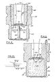
- a combustion pressure sensor 10 includes a thin lower steel diaphragm 12 which may be flat or corrugated, for additional compliance, and an upper steel diaphragm 14.
- a temperature tolerant liquid 16 is located between diaphragms 12 and 14 and contained within a cylindrical wall member 18.
- Cylindrical wall member 18 has external threads 20 for engaging threads in an opening leading to the combustion chamber of an internal combustion engine.
- a filling channel 22 is formed into wall 18 so as to provide external access to the volume between diaphragms 12 and 14.
- a pinch-off tube 24 is at the external port of filling channel 22 so as to provide a means of sealing the volume 16.
- Lower diaphragm 12 is bonded to wall 18.
- Upper diaphragm 14 is butted and sealed against inwardly projecting ledge 26 of wall 18.
- a glass enamel insulating layer 34 is bonded to diaphragm 14 on the side opposite from liquid 16. Fired onto this enamel are two spaced thick film conductor terminations 28, and a thick film resistor 32 which partially overlaps terminations 28. Leads 30 are also bonded to terminations 28.
- a combustion pressure sensor 50 has a lower diaphragm 52 and an upper diaphragm 54. Bonded to lower diaphragm 52 and extending toward and touching upper diaphragm 54 is an elongated spindle 56 for transmitting force between the two diaphragms.
- An outer wall 58 is generally cylindrical and has bonded thereto lower diaphragm 52. Outer wall 58 has external threads 60 for engaging threads in an access opening to the combustion chamber of an internal combustion engine. Outer wall 58 also has an interior, washer-shaped flange 75 extending parallel to and between diaphragms 52 and 54, to serve as a radiation shield against radiant heat transfer between diaphragms 52 and 54.
- a central opening 76 in flange 75 passes spindle 56.
- Outer wall 58 also has internal threads 62 for engaging external threads 64 of an inner wall 66 which screws into the inside of wall 58 and holds upper diaphragm 54 against spindle 56 thereby mounting upper diaphragm 54 without bonding to inner wall 66.
- Upper diaphragm 54 includes a glass enamel covering 68, a pair of spaced thick film conductors 70 and a thick film resistor 72. Two conductive leads 74 are attached to thick film conductor 70 and conduct a power signal and an output signal.
- Sensors 10 and 50 can each be coupled to one cylinder of an internal combustion engine and be part of a feedback loop which contains a microprocessor to adjust combustion variables such as spark timing and air-fuel ratio to optimize the cylinder pressure profile during the power stroke.
- This profile is a direct measure of thermal efficiency.
- the shape of the profile is more important than the absolute magnitude of the cylinder pressure and an absolute accuracy of about 80 percent in the pressure measurement may be acceptable for many applications. Thus, the separate calibration for each sensor may be unnecessary.
- the duration of the important portion of the profile ranges from about 2 to about 20 milliseconds, depending on engine revolution rate.
- Sensors 10 and 50 are, additionally, capable of transmitting oscillations typical of engine knock in the frequency range of 6 to 10 kHz.
- the particular resistive structures of upper diaphragms 14 and 54 can be formed using various inks (or pastes) which have sheet resistances in the range of 10 2 to 10 5 ohms/square. A typical dimension of such a resistor would be about one millimeter.
- the fractional change in resistance per unit strain, i.e. the gauge factor, is in the range of 5 to 12 and is relatively temperature independent. While the resistance of the thick films is appreciably temperature sensitive, conventional temperature compensation is not needed. This simplification is permitted by the nature of the desired measurements, and by the thermal isolation between the two diaphragms.
- sensor 10 is similar to a spark plug fitting and has on the combustion side, flush with the cylinder ceiling, a thin, corrugated metallic transmission membrane serving as diaphragm 12. Above this, a layer of heat tolerant liquid 16 is inserted.
- the stiffer, enamel steel diaphragm 14 is above the liquid and has the thick film strain gauge on its upper surface, out of contact with liquid 16.
- Liquid 16 transmits pressure pulses instantaneously, while slowing down the transmission of temperature pulses such as the ones due to initial engine warmup.
- Lower diaphragm 12 is more delicate than upper diaphragm 14 but it is backed by an essentially incompressible liquid and is therefore effectively about as stiff as upper diaphragm 14 during positive pressure pulses.
- lower diaphragm 12 must be sufficiently stiff to be able to withstand the vacuum portion of the engine cycle.
- sensor 10 or 50 is a two- terminal device with only one strain sensitive resistor. If the strain gauge resistor of the proposed device is powered by a constant current source and there are no temperature changes, the resulting voltage drop during engine operation across the resistor, constituting the output signal, is shown in Fig. 3A as Vs.
- the instantaneous values of the voltage signal are: where 6 is the fractional change in resistance caused by the pressure-induced strain in the resistor.
- the upper diaphragm will be designed so that its maximum strain, at maximum expected cylinder pressure, is about 0.001, well within the elastic range of the diaphragm. For an expected gauge factor of about 10, the maximum value of 6 will be about 0.01. In other words, the voltage output from the resistor will rise by no more than one percent, and the major portion of the pulse will take place in less than about 90° of crank angle, with a pulse repetition every 720° of crank angle.
- the time-averaged voltage is only slightly above the baseline voltage: where s is the strain, G is the gauge factor, p the pressure, and G' is an effective gauge factor for the device, incorporating the elastic properties of the upper diaphragm. G and G' are substantially temperature independent.
- V b can be measured at the precise crank angle at which the pressure is known to be zero.
- the minimum voltage value corresponding to a partial vacuum, is an excellent approximation to V b .
- Analog circuits for capturing transient voltage minima are well known. Thus, pressure can be determined from the known constants V b and G' and from the instantaneous signal V s .
- Fig. 3B schematically depicts the more realistic case where R o drifts due to temperature changes and/or aging.
- a constant current source is assumed.
- the device will be satisfactory if, in the intervals between points p and q of Fig. 3B, V b (q) - V b (p) can be kept acceptably small, relative to the magnitude of V s during the pressure pulse between p and q.
- Fig. 3C is an enlargement of the portion of Fig.
- Diaphragms 54 and 14, those spaced away from the combustion chamber, are advantageously formed of a steel compatible with an electronic grade glass enamel which is a good electrical insulator.
- a resistor paste and a conductor paste are formed on the glass enamel.
- a particularly advantageous steel is type 316 stainless steel which is capable of forming a good bond to electronic grade glass enamels and has a higher yield strength, after the enamelling, than typical enamelling steels.
- decarburized silicon steel which is capable of being glass enamelled, yet retains a higher yield strength, after cooling down from the enamelling temperature of about 900°C than other known enamelling steels.
- diaphragms 54 and 14 can be formed of alumina plate or other ceramic plate onto which compatible resistor and conductive pastes are formed.
- Diaphragms 52 and 12 are typically very thin flat steel alloy materials with good corrosion resistance and strength at high temperatures. If desired, diaphragms 52 and 12 may also have concentric circular corrugations for added comp- liancy.
- a combustion pressure sensor 450 is similar to combustion pressure sensor 50 of Fig. 2.
- a lower diaphragm 452 has a corrugation or indentation extending into sensor 450 to facilitate upward movement.
- An elongated spindle 456 extends from lower diaphragm 452 to an upper diaphragm 454.
- An outer wall 458 is generally cylindrical and has bonded thereto lower diaphragm 452.
- Outer wall 458 has external threads 460 for engaging threads in an access opening to the combustion chamber of an internal combustion engine. Outer wall 458 also has an interior annular flange 475 extending parallel to and between diaphragms 452 and 454, to serve as a radiation shield against radiant heat transfer between diaphragms 452 and 454. A central opening 476 in annular flange 475 passes spindle 456. Outer wall 458 also has internal threads 462 for engaging external threads 464 of an inner wall 466 which screws into the inside of wall 458 and holds upper diaphragm 454 against spindle 456 thereby mounting upper diaphragm 454 without bonding to inner wall 466.
- inner wall 466 is chamfered in order to define a circle of support on upper diaphragm 454.
- Inner wall 466 extends well above wall 458 to permit installation of a hexagonal locknut 459. Further, the upper portion of inner wall 466 has an internal thread for mounting a lead through and anchor for conductive leads 474.
- Upper diaphragm 454 includes a glass enamel covering 468, a pair of spaced thick film conductors 470 and a thick film resistor 472, which are all not drawn to scale.
- the particular mounting of the diaphragms may be varied from that disclosed herein.
- Other materials can be used for the upper diaphragm.
- glass enamelled steel it could be formed of other metals to which a glass enamel insulating layer, a ceramic insulating layer, or any high temperature tolerant insulating layer has been intimately bonded.
- a strain sensitive resistor would, in turn, be bonded to this insulating layer.
- the second diaphragm could be formed of an electrically insulating ceramic to which a strain sensitive resistor is directly bonded.
- the elongated spindle can be formed of various materials having low heat conductivity and low heat diffusivity.
Landscapes
- Physics & Mathematics (AREA)
- General Physics & Mathematics (AREA)
- Chemical & Material Sciences (AREA)
- Engineering & Computer Science (AREA)
- Combustion & Propulsion (AREA)
- Measuring Fluid Pressure (AREA)
Claims (7)
Applications Claiming Priority (2)
| Application Number | Priority Date | Filing Date | Title |
|---|---|---|---|
| US53348383A | 1983-09-19 | 1983-09-19 | |
| US533483 | 1995-09-25 |
Publications (3)
| Publication Number | Publication Date |
|---|---|
| EP0145146A2 EP0145146A2 (de) | 1985-06-19 |
| EP0145146A3 EP0145146A3 (en) | 1988-08-31 |
| EP0145146B1 true EP0145146B1 (de) | 1990-11-22 |
Family
ID=24126148
Family Applications (1)
| Application Number | Title | Priority Date | Filing Date |
|---|---|---|---|
| EP19840306355 Expired EP0145146B1 (de) | 1983-09-19 | 1984-09-18 | Verbrennungsdrucksensor |
Country Status (3)
| Country | Link |
|---|---|
| EP (1) | EP0145146B1 (de) |
| JP (1) | JPS6073428A (de) |
| DE (1) | DE3483641D1 (de) |
Families Citing this family (15)
| Publication number | Priority date | Publication date | Assignee | Title |
|---|---|---|---|---|
| US4617607A (en) * | 1985-12-10 | 1986-10-14 | Kavlico Corporation | High pressure capacitive transducer |
| IN169553B (de) * | 1987-12-11 | 1991-11-09 | Int Control Automation Finance | |
| DE3811311C1 (de) * | 1988-04-02 | 1989-03-09 | Robert Bosch Gmbh, 7000 Stuttgart, De | |
| US5043841A (en) * | 1989-06-13 | 1991-08-27 | Bishop Robert P | High pressure transducer package |
| GB2244335B (en) * | 1990-05-24 | 1994-03-23 | Stc Plc | High pressure sensor |
| JPH0443933A (ja) * | 1990-06-11 | 1992-02-13 | Mitsubishi Electric Corp | 圧力センサ |
| CA2162201A1 (en) * | 1994-11-07 | 1996-05-08 | Matsushita Electric Industrial Co., Ltd. | Combustion pressure sensor and fabrication method thereof |
| FR2733831B1 (fr) * | 1995-05-04 | 1997-06-20 | Inst Francais Du Petrole | Capteur de vibrations |
| DE29718464U1 (de) * | 1997-10-17 | 1997-12-18 | Giese, Erhard, Dr., 24941 Flensburg | Drucksensorelement |
| JP2006250614A (ja) * | 2005-03-09 | 2006-09-21 | Denso Corp | 圧力検出装置 |
| JP4525297B2 (ja) * | 2004-10-28 | 2010-08-18 | 株式会社デンソー | 圧力検出装置 |
| DE102005004603B3 (de) * | 2005-02-01 | 2006-06-08 | Siemens Ag | Kraftsensor |
| JP6297986B2 (ja) * | 2015-01-14 | 2018-03-20 | 長野計器株式会社 | センサモジュール及びセンサモジュールの製造方法 |
| WO2023117856A1 (en) * | 2021-12-21 | 2023-06-29 | Biotronik Se & Co. Kg | Pressure sensor |
| AT525353B1 (de) * | 2021-12-22 | 2023-03-15 | Piezocryst Advanced Sensorics | Drucksensor für statische und dynamische druckmessungen |
Family Cites Families (7)
| Publication number | Priority date | Publication date | Assignee | Title |
|---|---|---|---|---|
| US3313962A (en) * | 1963-04-05 | 1967-04-11 | Messrs Kistler Instr A G | Piezo-electric transducer |
| US3697917A (en) * | 1971-08-02 | 1972-10-10 | Gen Electric | Semiconductor strain gage pressure transducer |
| JPS5461975A (en) * | 1977-10-26 | 1979-05-18 | Hitachi Ltd | Detector of differential pressure, pressure and load |
| JPS54113379A (en) * | 1978-02-23 | 1979-09-04 | Nec Corp | Pressure gauge |
| US4169388A (en) * | 1978-12-13 | 1979-10-02 | The Bendix Corporation | Integrated spark plug-combustion pressure sensor |
| US4382377A (en) * | 1980-05-16 | 1983-05-10 | Siemens Aktiengesellschaft | Pressure sensor for an internal combustion engine |
| JPS57147018A (en) * | 1981-03-06 | 1982-09-10 | Nippon Soken Inc | Knocking detector for internal combustion engine |
-
1984
- 1984-07-26 JP JP15415784A patent/JPS6073428A/ja active Pending
- 1984-09-18 DE DE8484306355T patent/DE3483641D1/de not_active Expired - Lifetime
- 1984-09-18 EP EP19840306355 patent/EP0145146B1/de not_active Expired
Also Published As
| Publication number | Publication date |
|---|---|
| EP0145146A2 (de) | 1985-06-19 |
| JPS6073428A (ja) | 1985-04-25 |
| DE3483641D1 (de) | 1991-01-03 |
| EP0145146A3 (en) | 1988-08-31 |
Similar Documents
| Publication | Publication Date | Title |
|---|---|---|
| US4586018A (en) | Combustion pressure sensor | |
| EP0145146A2 (de) | Verbrennungsdrucksensor | |
| US5712428A (en) | Pressure sensor with a solid to minimize temperature-related measurement error | |
| EP0473109B1 (de) | Druckmassfühler | |
| US6089097A (en) | Elongated pressure sensor for a pressure transmitter | |
| US5024098A (en) | Pressure sensor useable in oil wells | |
| US5186054A (en) | Capacitive pressure sensor | |
| EP0164413B1 (de) | Druckwandler | |
| US6295875B1 (en) | Process pressure measurement devices with improved error compensation | |
| US20060278005A1 (en) | Pressure sensor using compressible sensor body | |
| US5209121A (en) | Pressure sensor | |
| JP3325879B2 (ja) | 相対圧センサ | |
| US4741214A (en) | Capacitive transducer with static compensation | |
| US5877425A (en) | Semiconductor-type pressure sensor with sensing based upon pressure or force applied to a silicon plate | |
| US8443676B2 (en) | Pressure sensor for hydraulic media in motor vehicle brake systems | |
| US4262540A (en) | Pressure measuring device | |
| US5353643A (en) | Pressure sensor | |
| JPH0578775B2 (de) | ||
| JPH109979A (ja) | ドライタイプ圧力検出装置 | |
| JP3081352B2 (ja) | 圧力センサ | |
| JPH0295232A (ja) | 圧電型圧力センサ | |
| JPH0434327A (ja) | 燃焼圧力センサ | |
| RU2028583C1 (ru) | Датчик давления | |
| JPH0674848A (ja) | 圧力センサー | |
| JPH1194667A (ja) | 圧力センサ |
Legal Events
| Date | Code | Title | Description |
|---|---|---|---|
| PUAI | Public reference made under article 153(3) epc to a published international application that has entered the european phase |
Free format text: ORIGINAL CODE: 0009012 |
|
| AK | Designated contracting states |
Designated state(s): DE FR GB |
|
| PUAL | Search report despatched |
Free format text: ORIGINAL CODE: 0009013 |
|
| AK | Designated contracting states |
Kind code of ref document: A3 Designated state(s): DE FR GB |
|
| RHK1 | Main classification (correction) |
Ipc: G01L 19/06 |
|
| 17P | Request for examination filed |
Effective date: 19890124 |
|
| 17Q | First examination report despatched |
Effective date: 19891011 |
|
| GRAA | (expected) grant |
Free format text: ORIGINAL CODE: 0009210 |
|
| AK | Designated contracting states |
Kind code of ref document: B1 Designated state(s): DE FR GB |
|
| REF | Corresponds to: |
Ref document number: 3483641 Country of ref document: DE Date of ref document: 19910103 |
|
| ET | Fr: translation filed | ||
| REG | Reference to a national code |
Ref country code: GB Ref legal event code: 746 |
|
| PLBE | No opposition filed within time limit |
Free format text: ORIGINAL CODE: 0009261 |
|
| STAA | Information on the status of an ep patent application or granted ep patent |
Free format text: STATUS: NO OPPOSITION FILED WITHIN TIME LIMIT |
|
| 26N | No opposition filed | ||
| REG | Reference to a national code |
Ref country code: FR Ref legal event code: DL |
|
| PGFP | Annual fee paid to national office [announced via postgrant information from national office to epo] |
Ref country code: GB Payment date: 19980814 Year of fee payment: 15 |
|
| PGFP | Annual fee paid to national office [announced via postgrant information from national office to epo] |
Ref country code: DE Payment date: 19980905 Year of fee payment: 15 |
|
| PGFP | Annual fee paid to national office [announced via postgrant information from national office to epo] |
Ref country code: FR Payment date: 19980917 Year of fee payment: 15 |
|
| PG25 | Lapsed in a contracting state [announced via postgrant information from national office to epo] |
Ref country code: GB Free format text: LAPSE BECAUSE OF NON-PAYMENT OF DUE FEES Effective date: 19990918 |
|
| GBPC | Gb: european patent ceased through non-payment of renewal fee |
Effective date: 19990918 |
|
| PG25 | Lapsed in a contracting state [announced via postgrant information from national office to epo] |
Ref country code: FR Free format text: LAPSE BECAUSE OF NON-PAYMENT OF DUE FEES Effective date: 20000531 |
|
| PG25 | Lapsed in a contracting state [announced via postgrant information from national office to epo] |
Ref country code: DE Free format text: LAPSE BECAUSE OF NON-PAYMENT OF DUE FEES Effective date: 20000701 |
|
| REG | Reference to a national code |
Ref country code: FR Ref legal event code: ST |