EP0145670B1 - Device for forming loops of printed fabrics - Google Patents
Device for forming loops of printed fabrics Download PDFInfo
- Publication number
- EP0145670B1 EP0145670B1 EP84830242A EP84830242A EP0145670B1 EP 0145670 B1 EP0145670 B1 EP 0145670B1 EP 84830242 A EP84830242 A EP 84830242A EP 84830242 A EP84830242 A EP 84830242A EP 0145670 B1 EP0145670 B1 EP 0145670B1
- Authority
- EP
- European Patent Office
- Prior art keywords
- rods
- chains
- arms
- rails
- links
- Prior art date
- Legal status (The legal status is an assumption and is not a legal conclusion. Google has not performed a legal analysis and makes no representation as to the accuracy of the status listed.)
- Expired
Links
- 239000004744 fabric Substances 0.000 title claims abstract description 44
- 238000011144 upstream manufacturing Methods 0.000 claims description 11
- 230000000284 resting effect Effects 0.000 claims description 3
- 238000010025 steaming Methods 0.000 abstract description 8
- 230000015572 biosynthetic process Effects 0.000 description 7
- 230000001174 ascending effect Effects 0.000 description 3
- 230000000694 effects Effects 0.000 description 2
- 230000007246 mechanism Effects 0.000 description 2
- 239000004753 textile Substances 0.000 description 2
- 230000005540 biological transmission Effects 0.000 description 1
- 238000007796 conventional method Methods 0.000 description 1
- 230000007547 defect Effects 0.000 description 1
- 230000002950 deficient Effects 0.000 description 1
- 238000004043 dyeing Methods 0.000 description 1
- 230000005484 gravity Effects 0.000 description 1
- 238000012423 maintenance Methods 0.000 description 1
- 238000004519 manufacturing process Methods 0.000 description 1
- 239000000463 material Substances 0.000 description 1
- 238000000034 method Methods 0.000 description 1
- 230000000717 retained effect Effects 0.000 description 1
- 238000005096 rolling process Methods 0.000 description 1
Images



Classifications
-
- D—TEXTILES; PAPER
- D06—TREATMENT OF TEXTILES OR THE LIKE; LAUNDERING; FLEXIBLE MATERIALS NOT OTHERWISE PROVIDED FOR
- D06B—TREATING TEXTILE MATERIALS USING LIQUIDS, GASES OR VAPOURS
- D06B17/00—Storing of textile materials in association with the treatment of the materials by liquids, gases or vapours
- D06B17/06—Storing of textile materials in association with the treatment of the materials by liquids, gases or vapours in festooned form
-
- D—TEXTILES; PAPER
- D06—TREATMENT OF TEXTILES OR THE LIKE; LAUNDERING; FLEXIBLE MATERIALS NOT OTHERWISE PROVIDED FOR
- D06B—TREATING TEXTILE MATERIALS USING LIQUIDS, GASES OR VAPOURS
- D06B19/00—Treatment of textile materials by liquids, gases or vapours, not provided for in groups D06B1/00 - D06B17/00
- D06B19/0005—Fixing of chemicals, e.g. dyestuffs, on textile materials
- D06B19/0029—Fixing of chemicals, e.g. dyestuffs, on textile materials by steam
- D06B19/0035—Fixing of chemicals, e.g. dyestuffs, on textile materials by steam the textile material passing through a chamber
-
- D—TEXTILES; PAPER
- D06—TREATMENT OF TEXTILES OR THE LIKE; LAUNDERING; FLEXIBLE MATERIALS NOT OTHERWISE PROVIDED FOR
- D06B—TREATING TEXTILE MATERIALS USING LIQUIDS, GASES OR VAPOURS
- D06B23/00—Component parts, details, or accessories of apparatus or machines, specially adapted for the treating of textile materials, not restricted to a particular kind of apparatus, provided for in groups D06B1/00 - D06B21/00
- D06B23/04—Carriers or supports for textile materials to be treated
Definitions
- the present invention relates to a machine or apparatus for folding and treating fabrics. More particularly, but not exclusively, the invention relates to a folding machine or apparatus for steaming printed fabrics.
- a machine for treating (for example, preparing, steaming, dyeing, finishing, improving and the like) folded fabrics generally includes a treatment chamber in which an endless conveyor is supported for transferring the fabric to be treated from an inlet side of the chamber, where a roller for supporting and feeding the fabric operates, to an outlet side of the treatment chamber.
- Such a conveyor is constituted by a pair of endless chains supported and located close to the longitudinal walls of the chamber, the active and return passes of the chains extending close to the top and the bottom of the chamber respectively.
- a plurality of rollers termed rods in the art and in the following description, have ends connected mechanically to opposing links of the chains and are used to support the folded fabrics within the treatment chamber.
- a conveyor of the said type is advanced stepwise both to allow the formation of successive folds of fabric on successive rods close to the inlet side and to provide the necessary dwell time for the folded fabric in the treatment chamber.
- folding devices with various operational and structural characteristics are used which, in most cases, operate between the roller for supporting and feeding the fabric and the first rod downstream of this roller in the direction of movement of the conveyor.
- the function of starting the formation of the fold is entrusted to these devices and the fold is then completed by gravity.
- the folding devices press on the portion of fabric between the feed roller and the first rod for a limited period of time until the fold being formed has reached a certain size (length) and then, for safety, follow the fold during formation until it is completed.
- a second disadvantage lies in the incomplete reliability in operation of the said device for unhooking, accelerated driving and re-hooking of the rods. Defective operation of this device may require the stoppage of the machine as well as of the entire' production line in which it is incorporated.
- Such a device has a complex structure which is difficult and laborious to put into operation and requires frequent control and maintenance.
- the problem at the root of the present invention is that of providing a machine, particularly for steaming printed fabrics, which effects the folding of the fabric by contacting the reverse side only of the fabric, without unhooking the rods from the chains.
- a machine for folding and treating printed fabrics comprising a treatment chamber, a conveyor including a pair of endless chains having a plurality of links and a plurality of rods carried by the links of the chains, which have active passes extending in the chamber between an inlet and an outlet for the fabric, and a pair of straight rails extending above and parallel to the active passes of the chains, characterised in that each rod is suspended from opposite links of the respective conveyor chains by means of a pair of arms hinged to said opposite respective links of the chains and to opposite respective ends of the rod, and in that lift means are provided with respective arms rotatable about an axis parallel to the rods, supported upstream of the rails in a position overlying the active passes of the chains, the arms describing a substantially circular path in which they interfere with the individual rods in succession when the rods are suspended by their arms from the said links upstream of the rails, to lift successive rods from the suspended condition to a condition of resting on the rails.
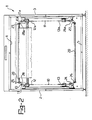
- a machine for folding and treating fabrics particularly for steaming printed fabrics, includes a parallelepiped shaped chamber 1 the longitudinal walls of which are indicated 2, 3 and the top and the bottom are indicated 4 and 5, respectively, the chamber having at its front end an inlet aperture 6 for the fabric to be treated and at its rear, upper end an outlet aperture 7 for the treated fabric.
- roller 8 In correspondence with the aperture 6 a roller 8 is rotatably supported in the chamber 1 for supporting and feeding the fabric, and an idle roller, indicated 9, for supporting the fabric is located close to the outlet aperture 7. Both the rollers 8, 9 have horizontal axes perpendicular to the walls 2, 3.
- a conveyor (T) is supported in the chamber 1 and is constituted essentially by a pair of endless chains 10, 10a of conventional type used in the art and schematically indicated in chain line in the appended drawings. Chains 10, 10a have respective links 11, 11a.
- the chain 10 is supported and located close to the longitudinal wall 2 by respective sprocket wheels 12, 13, 14 and 15 all with their axes horizontal and perpendicular to the said wall.
- the wheel 12 supported close to the outlet aperture 7 is a drive wheel.
- the upper active pass 16 of the chain 10 extends horizontally between the inlet and outlet openings 6, 7 for the fabric and in a position underlying these while the lower return pass 17 extends horizontally close to the bottom 5 of the chamber.
- Reference 18 indicates the front ascending pass of the chain 10, which extends vertically in correspondence with the roller 8 for feeding the fabric and reference 19 indicates the rear vertical descending pass of the chain.
- the chain 10a is identical to the chain 10 and is similarly supported close to the longitudinal wall 3 of the chamber 1. All the parts relative to the chain 10a have the same reference numerals as those for the chain 10 with the addition of the suffix a.
- Reference 20 indicates each rod of a plurality of rods for supporting the folded fabric, each rod having opposite ends connected mechanically to opposing links 11, 11a of the chains 10, 10a.
- each rod 20 has pins 21, 22 at opposite ends on which the ends 23, 23a of arms 24, 24a are rotatably mounted, the opposite ends 25, 25a of these arms being rotatably mounted on the opposing links 11, 11a of the chains 10, 10a.
- each rod 20 is thus suspended from opposite points on the chains 10, 10a, being freely rotatable in one sense or in the opposite sense about these points.
- each rod 20 On the pins 21, 22 of each rod 20 respective rollers 26, 27 are rotatably mounted for engaging, in the manner described below, respective upper rails 28, 28a and lower rails 29, 29a.
- the upper rails 28, 28a extend above the active passes 16, 16a of the chains 10, 10am which they are spaced by distance less than the length of the arms 24 and preferably equal to about half this length.
- a plate 30 disposed vertically and in a position facing the sprocket wheel 15 in question.
- the plate 30 has a front edge 31 with a vertical section 32 extending close to the ascending portion 18 of the chain 10 on the inner side of this chain.
- the upper end 33 of the portion 32 of the front edge 31 is at a level above the horizontal line passing through the centre of the sprocket wheel 15 and is connected to a descending curved edge 34 preferably passing through the centre of the wheel 15 and extending close to the periphery thereof.
- edges 31 and 34 suffices to guide the roller 26 of each rod 20, as will become clearer from the description below.
- a further plate similar to and symmetrical with respect to the plate 30 described above. This further plate with its vertical and curved edges is not shown, to simplify the drawings.
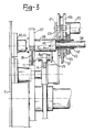
- a gear wheel 36 rigid with the sprocket wheel 15 for rotation therewith and meshing with a pinion 37.
- the pinion 37 is keyed to a horizontal shaft 38 rotatably supported conventionally by supports 40, 41 fixed to the opposite longitudinal walls 2, 3 of the chamber 1.
- the gear ratio between the gear wheel 36 and its pinion 37 is 4:1.
- a hub 42 on a rectangular plate-shaped body 43 is keyed to the shaft 38 close to the pinion 37, the body 43 being parallel to the wall 2 and adjacent the inside surface of the upper rail 28.
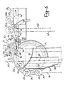
- the plate-shaped body 43 has pins 44, 45 ( Figure 4) on its opposite sides on which are rotatably mounted the short arms 46, 47 of two similar cranked levers 48, 49, the larger ends of which extend outwardly of the plate-shaped body 43 and are indicated 50, 51.
- Each of the cranked levers 48, 49 has a lug 52, 53 which is effectively an elongation of the respective longer arms 50, 51 and on the opposite side thereof.
- These lugs 52, 53 are bifurcated and support respective cam-follower rollers 54, 55.
- the rollers 54, 55 are in rolling contact with the profile 56 of a fixed cam 57 mounted coaxially about the shaft 38 by structurally independent thereof.
- the profile 56 of the cam 57 includes a circular portion which subtends an angle of 270° at the centre of the cam and faces the edge 34 mentioned above ( Figures 4-6) and a sharply re-entrant portion, indicated 58, facing the rail 28.
- a lift S' entirely similar to that described above is mounted on the shaft 38 close to the longitudinal wall 3 of the treatment chamber 1. All the components of this second lift S' are identified by the same reference numerals as those of the components of the lift S with the addition of the suffix a. It should be noted that the distance between the roller 8 for supporting and feeding the fabric at the inlet and the first rod 20 of the active pass of the conveyor T is equal to or slightly greater than the size of the lift S measured in the direction of movement of the conveyor itself.
- the printed fabric fed into the chamber 1 by the feed roller 8 is supported in a folded disposition F by the rods 20 which pass along the upper pass 16-16a of the conveyor, this conveyor being advanced stepwise in an entirely conventional manner.
- the fabric is taken up, again by a conventional method, and discharged from the steaming chamber through the outlet aperture 7.
- the rods move in a suspended condition and in this same condition are raised through the front ascending passes 18, 18a, of the conveyor.
- Close to the upper end of these front passes 18, 18a and rollers 26, 27 of the rods 20 encounter the front edges 31-32 of the plates 30-30a which prevent the rods 20 for maintaining the normally suspended condition.
- the advancing step of the chains 10, 10a is such that, at each step, a rod 20 is held by the upper ends 33 of the edges 31, 32 of the plate 30.
- a rod 20a is held by the upper end 33 of the edge 31-32 of the plate 30; a rod 20b is in the position immediately upstream of the upper rail 28 and is supported in this position by the arm 51 of the lever 49 of the lift S.
- roller 55 of the lever 49 bears on the cam profile 56 at a point immediately preceding the re-entrant portion 58 of this profile.
- Reference 20c indicates the rod which follows the rod 20a mentioned above and which is retained by the vertical section 32 of the edge 31 of the plate 30.
- the conveyor effects a stepwise advance while the fabric is continuously fed at a predetermined rate from the roller 8.
Landscapes
- Engineering & Computer Science (AREA)
- Chemical & Material Sciences (AREA)
- Materials Engineering (AREA)
- Textile Engineering (AREA)
- Treatment Of Fiber Materials (AREA)
- Folding Of Thin Sheet-Like Materials, Special Discharging Devices, And Others (AREA)
Priority Applications (1)
| Application Number | Priority Date | Filing Date | Title |
|---|---|---|---|
| AT84830242T ATE30931T1 (de) | 1983-10-07 | 1984-08-28 | Vorrichtung zum bilden von haengeschlaufen aus bedruckten geweben. |
Applications Claiming Priority (2)
| Application Number | Priority Date | Filing Date | Title |
|---|---|---|---|
| IT23203/83A IT1172415B (it) | 1983-10-07 | 1983-10-07 | Dispositivo faldatore per macchine per il trattamento di tessuti in falda,particolarmente di tessuti stampati |
| IT2320383 | 1983-10-07 |
Publications (2)
| Publication Number | Publication Date |
|---|---|
| EP0145670A1 EP0145670A1 (en) | 1985-06-19 |
| EP0145670B1 true EP0145670B1 (en) | 1987-11-19 |
Family
ID=11204851
Family Applications (1)
| Application Number | Title | Priority Date | Filing Date |
|---|---|---|---|
| EP84830242A Expired EP0145670B1 (en) | 1983-10-07 | 1984-08-28 | Device for forming loops of printed fabrics |
Country Status (9)
| Country | Link |
|---|---|
| US (1) | US4560099A (it) |
| EP (1) | EP0145670B1 (it) |
| JP (1) | JPH0620975B2 (it) |
| AT (1) | ATE30931T1 (it) |
| BR (1) | BR8404980A (it) |
| DD (1) | DD224630A5 (it) |
| DE (1) | DE3467597D1 (it) |
| ES (1) | ES8507205A1 (it) |
| IT (1) | IT1172415B (it) |
Cited By (1)
| Publication number | Priority date | Publication date | Assignee | Title |
|---|---|---|---|---|
| CN106471174A (zh) * | 2014-05-21 | 2017-03-01 | 阿雷欧利有限公司 | 用于处理折叠的印花织物的机器 |
Families Citing this family (6)
| Publication number | Priority date | Publication date | Assignee | Title |
|---|---|---|---|---|
| NL190560C (nl) * | 1988-12-13 | 1994-04-18 | Stork Brabant Bv | Inrichting voor het fixeren van op banen textieldoek gedrukte pasta's. |
| DE4214674C1 (it) * | 1992-05-02 | 1993-08-19 | Babcock Textilmaschinen Gmbh, 2105 Seevetal, De | |
| US5494205A (en) * | 1994-03-09 | 1996-02-27 | Guilford Mills, Inc. | Apparatus for festooning a traveling length of web-like material |
| US6109498A (en) * | 1998-12-30 | 2000-08-29 | Owens Corning Fiberglas Technology, Inc. | Shock absorber assembly for reducing breaks in an asphalt-coated sheet |
| ITTO20030118A1 (it) * | 2003-02-18 | 2004-08-19 | Arioli S P A | Dispositivo per la formazione di falde di tessuto di una macchina per il trattamento di tessuti. |
| EP3095906A1 (en) * | 2015-05-19 | 2016-11-23 | Has Trade S.r.l. | Machine for steaming fabrics |
Family Cites Families (8)
| Publication number | Priority date | Publication date | Assignee | Title |
|---|---|---|---|---|
| US1494307A (en) * | 1922-09-02 | 1924-05-13 | Vlaanderen Machine Company Van | Drying machine |
| US1755006A (en) * | 1928-07-03 | 1930-04-15 | Proctor And Schwartz Inc | Loop drier |
| US1990406A (en) * | 1932-07-28 | 1935-02-05 | Proctor & Schwartz Inc | Festooning mechanism for loop driers |
| US2814192A (en) * | 1950-07-08 | 1957-11-26 | Brunner August Jakob | Apparatus for liquid treating of fabric in a festoon-like arrangement |
| US3899902A (en) * | 1973-05-29 | 1975-08-19 | Fulvio Conti | Plant for steaming and fixing dyes at high or low temperature on printed or dyed fabrics |
| DE2404679C3 (de) * | 1974-02-01 | 1985-08-29 | Babcock-BSH AG vormals Büttner-Schilde-Haas AG, 4150 Krefeld | Vorrichtung zum Bilden und Fördern von Hängeschleifen |
| NL7408087A (nl) * | 1974-06-17 | 1975-12-19 | Stork Brabant Bv | Inrichting voor het afleveren en weer opnemen van horizontale staven, in het bijzonder voor een stomer. |
| DE3114608A1 (de) * | 1980-04-15 | 1982-04-29 | Sando Iron Works Co., Ltd., Wakayama | "verfahren zum kontinuierlichen hochtemperatur-mattieren und vorrichtung zum durchfuehren des verfahrens" |
-
1983
- 1983-10-07 IT IT23203/83A patent/IT1172415B/it active
-
1984
- 1984-08-28 DE DE8484830242T patent/DE3467597D1/de not_active Expired
- 1984-08-28 EP EP84830242A patent/EP0145670B1/en not_active Expired
- 1984-08-28 AT AT84830242T patent/ATE30931T1/de not_active IP Right Cessation
- 1984-09-20 US US06/652,828 patent/US4560099A/en not_active Expired - Lifetime
- 1984-09-25 ES ES536220A patent/ES8507205A1/es not_active Expired
- 1984-10-03 BR BR8404980A patent/BR8404980A/pt not_active IP Right Cessation
- 1984-10-05 JP JP59209613A patent/JPH0620975B2/ja not_active Expired - Lifetime
- 1984-10-05 DD DD84268071A patent/DD224630A5/de not_active IP Right Cessation
Cited By (1)
| Publication number | Priority date | Publication date | Assignee | Title |
|---|---|---|---|---|
| CN106471174A (zh) * | 2014-05-21 | 2017-03-01 | 阿雷欧利有限公司 | 用于处理折叠的印花织物的机器 |
Also Published As
| Publication number | Publication date |
|---|---|
| BR8404980A (pt) | 1985-08-20 |
| ATE30931T1 (de) | 1987-12-15 |
| EP0145670A1 (en) | 1985-06-19 |
| DE3467597D1 (en) | 1987-12-23 |
| JPH0620975B2 (ja) | 1994-03-23 |
| JPS6099065A (ja) | 1985-06-01 |
| IT8323203A0 (it) | 1983-10-07 |
| IT1172415B (it) | 1987-06-18 |
| US4560099A (en) | 1985-12-24 |
| IT8323203A1 (it) | 1985-04-07 |
| ES536220A0 (es) | 1985-09-01 |
| ES8507205A1 (es) | 1985-09-01 |
| DD224630A5 (de) | 1985-07-10 |
Similar Documents
| Publication | Publication Date | Title |
|---|---|---|
| US4646908A (en) | Apparatus for stacking packages in particular for wrapping installations using a strip of heat-shrinkable material | |
| US4560099A (en) | Folding device for machines for treating folded fabrics, particularly printed fabrics | |
| EP3527707B1 (en) | A machine for treating folded printed fabrics | |
| CA1072592A (en) | Conveying unit for feeding portions of sheet material, particularly preshaped or punched pieces of cardboard or the like, to a user machine, particularly a machine for packaging cigarettes into hinged lid packets | |
| EP1595018B1 (en) | Device for forming fabric folds in a machine for treating fabrics | |
| CA1239895A (en) | Apparatus for arranging articles in groups | |
| US2799381A (en) | Continuous veneer feeder | |
| JPS62282059A (ja) | サイズ付着器 | |
| KR900004479B1 (ko) | 제과장치 | |
| US2570030A (en) | Endless chain conveyer | |
| JP2001073283A (ja) | 布帛の滞留処理機におけるループの配列装置 | |
| HK1089798B (en) | Device for forming fabric folds in a machine for treating fabrics | |
| US1989977A (en) | Machine for treating fabrics | |
| US3312332A (en) | Conveying mechanism for a stocking boarding apparatus | |
| US3521803A (en) | Dyehouse unloader | |
| US5906061A (en) | Device for folding and discharging linen for a dry pressing machine and dry pressing machine incorporating such a device | |
| JP2755491B2 (ja) | 滞留ユニット | |
| US3557528A (en) | Closing machine for egg cartons or the like | |
| US2883032A (en) | Article transfer apparatus | |
| SU737536A1 (ru) | Поточна лини дл глажени и складывани изделий | |
| US1915872A (en) | Rayon bleaching machine | |
| US1684803A (en) | Folding machine | |
| US5474246A (en) | Apparatus for continuously treating a tape-like article | |
| KR0172964B1 (ko) | 환편기의 직물자동 당겨감기 , 배출장치 및 방법 | |
| US2664991A (en) | Traveling support for hank drying machines |
Legal Events
| Date | Code | Title | Description |
|---|---|---|---|
| PUAI | Public reference made under article 153(3) epc to a published international application that has entered the european phase |
Free format text: ORIGINAL CODE: 0009012 |
|
| AK | Designated contracting states |
Designated state(s): AT BE CH DE FR GB LI NL |
|
| 17P | Request for examination filed |
Effective date: 19850426 |
|
| 17Q | First examination report despatched |
Effective date: 19860610 |
|
| GRAA | (expected) grant |
Free format text: ORIGINAL CODE: 0009210 |
|
| AK | Designated contracting states |
Kind code of ref document: B1 Designated state(s): AT BE CH DE FR GB LI NL |
|
| REF | Corresponds to: |
Ref document number: 30931 Country of ref document: AT Date of ref document: 19871215 Kind code of ref document: T |
|
| REF | Corresponds to: |
Ref document number: 3467597 Country of ref document: DE Date of ref document: 19871223 |
|
| ET | Fr: translation filed | ||
| PLBE | No opposition filed within time limit |
Free format text: ORIGINAL CODE: 0009261 |
|
| STAA | Information on the status of an ep patent application or granted ep patent |
Free format text: STATUS: NO OPPOSITION FILED WITHIN TIME LIMIT |
|
| 26N | No opposition filed | ||
| PGFP | Annual fee paid to national office [announced via postgrant information from national office to epo] |
Ref country code: GB Payment date: 19980825 Year of fee payment: 15 Ref country code: AT Payment date: 19980825 Year of fee payment: 15 |
|
| PGFP | Annual fee paid to national office [announced via postgrant information from national office to epo] |
Ref country code: FR Payment date: 19980828 Year of fee payment: 15 |
|
| PGFP | Annual fee paid to national office [announced via postgrant information from national office to epo] |
Ref country code: BE Payment date: 19980831 Year of fee payment: 15 |
|
| PGFP | Annual fee paid to national office [announced via postgrant information from national office to epo] |
Ref country code: CH Payment date: 19980904 Year of fee payment: 15 |
|
| PGFP | Annual fee paid to national office [announced via postgrant information from national office to epo] |
Ref country code: DE Payment date: 19990811 Year of fee payment: 16 |
|
| PG25 | Lapsed in a contracting state [announced via postgrant information from national office to epo] |
Ref country code: GB Free format text: LAPSE BECAUSE OF NON-PAYMENT OF DUE FEES Effective date: 19990828 Ref country code: AT Free format text: LAPSE BECAUSE OF NON-PAYMENT OF DUE FEES Effective date: 19990828 |
|
| PG25 | Lapsed in a contracting state [announced via postgrant information from national office to epo] |
Ref country code: LI Free format text: LAPSE BECAUSE OF NON-PAYMENT OF DUE FEES Effective date: 19990831 Ref country code: CH Free format text: LAPSE BECAUSE OF NON-PAYMENT OF DUE FEES Effective date: 19990831 Ref country code: BE Free format text: LAPSE BECAUSE OF NON-PAYMENT OF DUE FEES Effective date: 19990831 |
|
| PGFP | Annual fee paid to national office [announced via postgrant information from national office to epo] |
Ref country code: NL Payment date: 19990831 Year of fee payment: 16 |
|
| BERE | Be: lapsed |
Owner name: ARIOLI & C. S.R.L. Effective date: 19990831 |
|
| REG | Reference to a national code |
Ref country code: CH Ref legal event code: PL |
|
| GBPC | Gb: european patent ceased through non-payment of renewal fee |
Effective date: 19990828 |
|
| PG25 | Lapsed in a contracting state [announced via postgrant information from national office to epo] |
Ref country code: FR Free format text: LAPSE BECAUSE OF NON-PAYMENT OF DUE FEES Effective date: 20000428 |
|
| REG | Reference to a national code |
Ref country code: FR Ref legal event code: ST |
|
| PG25 | Lapsed in a contracting state [announced via postgrant information from national office to epo] |
Ref country code: NL Free format text: LAPSE BECAUSE OF NON-PAYMENT OF DUE FEES Effective date: 20010301 |
|
| NLV4 | Nl: lapsed or anulled due to non-payment of the annual fee |
Effective date: 20010301 |
|
| PG25 | Lapsed in a contracting state [announced via postgrant information from national office to epo] |
Ref country code: DE Free format text: LAPSE BECAUSE OF NON-PAYMENT OF DUE FEES Effective date: 20010501 |