EP0146496A1 - Dispositif de transport continu et son application - Google Patents
Dispositif de transport continu et son application Download PDFInfo
- Publication number
- EP0146496A1 EP0146496A1 EP84810465A EP84810465A EP0146496A1 EP 0146496 A1 EP0146496 A1 EP 0146496A1 EP 84810465 A EP84810465 A EP 84810465A EP 84810465 A EP84810465 A EP 84810465A EP 0146496 A1 EP0146496 A1 EP 0146496A1
- Authority
- EP
- European Patent Office
- Prior art keywords
- drive
- conveyor belt
- transfer roller
- axis
- roller
- Prior art date
- Legal status (The legal status is an assumption and is not a legal conclusion. Google has not performed a legal analysis and makes no representation as to the accuracy of the status listed.)
- Withdrawn
Links
- 230000005540 biological transmission Effects 0.000 claims 2
- 238000004806 packaging method and process Methods 0.000 claims 1
- 230000002950 deficient Effects 0.000 abstract description 2
- 239000011324 bead Substances 0.000 description 1
- 238000005452 bending Methods 0.000 description 1
- 235000015895 biscuits Nutrition 0.000 description 1
- 238000005516 engineering process Methods 0.000 description 1
- 230000007613 environmental effect Effects 0.000 description 1
- 235000013305 food Nutrition 0.000 description 1
- 238000012423 maintenance Methods 0.000 description 1
- 238000011144 upstream manufacturing Methods 0.000 description 1
Images

Classifications
-
- B—PERFORMING OPERATIONS; TRANSPORTING
- B65—CONVEYING; PACKING; STORING; HANDLING THIN OR FILAMENTARY MATERIAL
- B65G—TRANSPORT OR STORAGE DEVICES, e.g. CONVEYORS FOR LOADING OR TIPPING, SHOP CONVEYOR SYSTEMS OR PNEUMATIC TUBE CONVEYORS
- B65G21/00—Supporting or protective framework or housings for endless load-carriers or traction elements of belt or chain conveyors
- B65G21/02—Supporting or protective framework or housings for endless load-carriers or traction elements of belt or chain conveyors consisting essentially of struts, ties, or like structural elements
- B65G21/06—Supporting or protective framework or housings for endless load-carriers or traction elements of belt or chain conveyors consisting essentially of struts, ties, or like structural elements constructed to facilitate rapid assembly or dismantling
Definitions
- the present invention relates to a continuous conveying device according to the preamble of independent claim 1, and to a use thereof according to claim 5.
- Such continuous conveyors in particular with a conveyor belt or belt, are known and are used in many areas of technology today. All these devices have in common that an infinite conveyor belt is guided over deflection rollers and is coupled to a drive. Such a drive can act directly on a deflection roller. Two of the deflection rollers, namely a downstream roller and an upstream roller, determine the upper run of the continuous conveyor, on which the goods are then transported.
- a disadvantage of such devices is that the conveyor belt sometimes. As a result of the bending stresses and also as a result of environmental influences, it can often show damage after a short time and must be replaced.
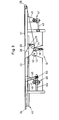
- 1 and 2 consists of a machine frame 10 and a cassette 20. Of the machine frame 10, only those necessary for operation are provided Parts shown, such as frame plate 11, drive shaft 12 with rigidly attached friction wheel 13 and transfer roller 14.
- This transfer roller 14 is rotatably mounted on a shaft 16 with guide element 17 and this guide element 17 is in turn guided and stands in a slot-shaped recess 18 for performing a translational movement under the bias by a coil spring 19. This arrangement is clearly shown in Fig. 2.
- the cassette 20 has a housing 21 which consists of two parallel housing plates 22, 23 and an upper guide table 22 ', with upper deflection rollers 24, 25 of a tensioning roller 26 and a drive roller 27 rotatably mounted between the housing plates 22, 23.
- the conveyor belt 28 wraps around all four rollers 24, 25, 26 and 27.
- the upper run 29 is stretched between the two upper deflection rollers 24, 25.
- Machine frame 10 and cassette 20 are provided with interlocking holding parts, by means of which the mutual position is precisely determined.
- the machine frame 10 has two outer bearing surfaces 30, 31 and side walls 32, 33 in the direction of flow and the cassette 20 is provided with support surfaces 34, 35 for bearing on the outer bearing surfaces.
- the exact mutual position is determined by means of pins 36 and guide openings 37.
- the pins 36 can additionally have locking notches or beads and locking springs can be provided in the guide openings 37. Since these holding elements are well known in the art, no further description has been given.
- the drive roller 27 presses against the transfer roller 14, which thus exerts a contact pressure determined by the spring 19 both against the friction wheel 13 and against the drive roller 27.
- the deflecting rollers 24, 25 therefore do not have to have any specific dimensions in order to achieve a specific transport speed because the drive is arranged elsewhere. Rollers with a smaller diameter can advantageously be used.
- defective conveyor belts 29 can be replaced by untrained personnel without any assembly effort and without significant interruption of operation, without having to pay attention to the exact fit of ball bearings or other bearing or tensioning elements.
- the maintenance work can then be carried out by qualified personnel or by the manufacturer of the transport system with care and without haste.
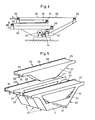
- Fig. 3 shows a universally usable cassette 40 with longitudinally variable guide table 41.
- the same parts as in Fig. 1 and 2 are denoted the same.
- the conveyor table 22 'shown in one piece in FIG. 2 consists of two partial tables 41, 42.
- Each of these partial tables 41, 42 is mounted on a rail 43, 44 so as to be longitudinally displaceable.
- the holder consists essentially of a support 45, 46 and a clamping part 47, 48.
- the rail 43 is fixed to the frame 40 on the cassette 40
- the rail 44 is on a carrier guide 49 inclined relative to the perpendicular to the cassette 40
- the mit.dem subtable 42 is integrally connected.
- the clamping part 48 By adjusting the clamping part 48, the sub-table 42 can then be moved toward or away from the sub-table 41 and held there.
- the carrier guide 49 can also be arranged displaceably together with the holder 50, in order thereby to be able to pivot the sub-table 42 away.
- a whole number of transport routes can be preset, or with actuators, such as hydraulic or pneumatic cylinders, the sub-table 42 can be made adjustable in height and distance.
- additional deflection rollers 51, 53 are provided, around which the conveyor belt 28 is also wrapped.
- the length of the upper run 29 of the conveyor belt 28 can be changed by moving the deflecting rollers 24, 51 together and, in addition, a lower run 52 can be pivoted, as arrows A and B show.
- the two lower deflection rollers 26, 53 are arranged on an additional guide part 54, which is accordingly tiltably supported, for example by the deflection roller 27 being arranged in a stationary manner, and the guide part 54 according to the arrangement in FIG. 3 with carrier guide 49 and holder 50 is adjustable in height.
- conveying equipment can also be combined according to FIG. 5.
- individual or groups of conveying equipment could also be arranged at an angle to one another if conveying lines from several delivery points or to several acceptance points are to be provided.
Landscapes
- Engineering & Computer Science (AREA)
- Mechanical Engineering (AREA)
- Structure Of Belt Conveyors (AREA)
Applications Claiming Priority (2)
| Application Number | Priority Date | Filing Date | Title |
|---|---|---|---|
| CH631083 | 1983-11-24 | ||
| CH6310/83 | 1983-11-24 |
Publications (1)
| Publication Number | Publication Date |
|---|---|
| EP0146496A1 true EP0146496A1 (fr) | 1985-06-26 |
Family
ID=4307524
Family Applications (1)
| Application Number | Title | Priority Date | Filing Date |
|---|---|---|---|
| EP84810465A Withdrawn EP0146496A1 (fr) | 1983-11-24 | 1984-09-24 | Dispositif de transport continu et son application |
Country Status (3)
| Country | Link |
|---|---|
| EP (1) | EP0146496A1 (fr) |
| JP (1) | JPS60132812A (fr) |
| BR (1) | BR8405739A (fr) |
Cited By (7)
| Publication number | Priority date | Publication date | Assignee | Title |
|---|---|---|---|---|
| GB2234725A (en) * | 1989-08-04 | 1991-02-13 | British Res Agricult Eng | Multi-section conveyor assembly |
| WO1997008084A1 (fr) * | 1995-08-24 | 1997-03-06 | Testamatic Limited | Transporteur, et assembleuse a transporteur incorpore |
| US6959803B1 (en) | 2002-12-18 | 2005-11-01 | Span Tech Llc | Self-tensioning conveyor |
| CN105540146A (zh) * | 2016-01-28 | 2016-05-04 | 张丰 | 一种模块化倍速链输送带 |
| US9399555B2 (en) | 2012-10-30 | 2016-07-26 | Tomra Systems Asa | Conveyor module docking system for a reverse vending machine |
| US20210032042A1 (en) * | 2019-08-01 | 2021-02-04 | Intelligrated Headquarters, Llc | Multi-belt conveyor system with removable cartridges |
| WO2023011691A1 (fr) * | 2021-08-06 | 2023-02-09 | Wipotec Gmbh | Dispositif de transport avec cassette de transport |
Families Citing this family (6)
| Publication number | Priority date | Publication date | Assignee | Title |
|---|---|---|---|---|
| JPS62196211A (ja) * | 1986-02-20 | 1987-08-29 | Hitachi Ltd | 搬送装置 |
| JPH066099Y2 (ja) * | 1986-08-08 | 1994-02-16 | 株式会社石田衡器製作所 | 商品の重量判定装置 |
| JPH0447148Y2 (fr) * | 1987-03-05 | 1992-11-06 | ||
| JPH031115U (fr) * | 1989-05-25 | 1991-01-08 | ||
| JPH0524652Y2 (fr) * | 1989-11-30 | 1993-06-23 | ||
| JP3188836B2 (ja) * | 1995-08-02 | 2001-07-16 | 三機工業株式会社 | ベルトコンベヤの駆動装置 |
Citations (2)
| Publication number | Priority date | Publication date | Assignee | Title |
|---|---|---|---|---|
| DE2161366B2 (de) * | 1970-12-11 | 1973-10-25 | Societe Des Aciers Fins De L'est, Boulogne-Billancourt, Seine (Frankreich) | Kettenförderer mit einem einen Motor Getriebeblock tragenden zentralen Grund gestell |
| EP0047837A2 (fr) * | 1980-09-12 | 1982-03-24 | Robert Bosch Gmbh | Mécanisme d'entraînement pour transporteurs à courroie |
-
1984
- 1984-09-24 EP EP84810465A patent/EP0146496A1/fr not_active Withdrawn
- 1984-11-09 BR BR8405739A patent/BR8405739A/pt unknown
- 1984-11-20 JP JP24357584A patent/JPS60132812A/ja active Pending
Patent Citations (2)
| Publication number | Priority date | Publication date | Assignee | Title |
|---|---|---|---|---|
| DE2161366B2 (de) * | 1970-12-11 | 1973-10-25 | Societe Des Aciers Fins De L'est, Boulogne-Billancourt, Seine (Frankreich) | Kettenförderer mit einem einen Motor Getriebeblock tragenden zentralen Grund gestell |
| EP0047837A2 (fr) * | 1980-09-12 | 1982-03-24 | Robert Bosch Gmbh | Mécanisme d'entraînement pour transporteurs à courroie |
Cited By (15)
| Publication number | Priority date | Publication date | Assignee | Title |
|---|---|---|---|---|
| GB2234725A (en) * | 1989-08-04 | 1991-02-13 | British Res Agricult Eng | Multi-section conveyor assembly |
| WO1997008084A1 (fr) * | 1995-08-24 | 1997-03-06 | Testamatic Limited | Transporteur, et assembleuse a transporteur incorpore |
| US6105756A (en) * | 1995-08-24 | 2000-08-22 | Testamatic Limited | Conveyor and converger incorporating a conveyor |
| US6959803B1 (en) | 2002-12-18 | 2005-11-01 | Span Tech Llc | Self-tensioning conveyor |
| US7308979B1 (en) | 2002-12-18 | 2007-12-18 | Span Tech Llc | Self-tensioning conveyor with slave drive |
| US9399555B2 (en) | 2012-10-30 | 2016-07-26 | Tomra Systems Asa | Conveyor module docking system for a reverse vending machine |
| EP2914518B1 (fr) * | 2012-10-30 | 2019-02-06 | Tomra Systems ASA | Module d'accueil de module de transporteur pour distributeur automatique inverse |
| EP3514083A1 (fr) * | 2012-10-30 | 2019-07-24 | Tomra Systems ASA | Module d'accueil de module de transporteur pour distributeur automatique inverse |
| CN105540146A (zh) * | 2016-01-28 | 2016-05-04 | 张丰 | 一种模块化倍速链输送带 |
| CN105540146B (zh) * | 2016-01-28 | 2017-09-19 | 张丰 | 一种模块化倍速链输送带 |
| US20210032042A1 (en) * | 2019-08-01 | 2021-02-04 | Intelligrated Headquarters, Llc | Multi-belt conveyor system with removable cartridges |
| US10988319B2 (en) * | 2019-08-01 | 2021-04-27 | Intelligrated Headquarters, Llc | Multi-belt conveyor system with removable cartridges |
| US11584591B2 (en) | 2019-08-01 | 2023-02-21 | Intelligrated Headquarters, Llc | Multi-belt conveyor system with removable cartridges |
| WO2023011691A1 (fr) * | 2021-08-06 | 2023-02-09 | Wipotec Gmbh | Dispositif de transport avec cassette de transport |
| US12583684B2 (en) | 2021-08-06 | 2026-03-24 | Wipotec Gmbh | Conveyor device with transport cassette |
Also Published As
| Publication number | Publication date |
|---|---|
| BR8405739A (pt) | 1985-09-17 |
| JPS60132812A (ja) | 1985-07-15 |
Similar Documents
| Publication | Publication Date | Title |
|---|---|---|
| DE4001050C2 (fr) | ||
| DE2142117C3 (de) | Schneidvorrichtung zum Trennen bewegter Bahnen in deren Längsrichtung in mehrere schmälere Bahnen | |
| WO1987004412A1 (fr) | Transporteur de pieces a usiner | |
| DE3928454A1 (de) | Kluppe und transportvorrichtung | |
| DE4006312A1 (de) | Fertigungsanlage zum bearbeiten und montieren von bauteilen | |
| EP0103122B1 (fr) | Presse à double ruban | |
| EP1075943B1 (fr) | Machine d'impression | |
| DE69906749T9 (de) | Vorrichtung zum transportieren und manipulieren von einer materialbahn | |
| DE69020503T2 (de) | Anlage zum Zuführen von einer Warenbahn. | |
| DE3113399A1 (de) | Ausrichtvorrichtung fuer die kanten eines aus falzprodukten bestehenden schuppenstroms | |
| DE69734789T2 (de) | Fadentraversiervorrichtung | |
| DE4422288B4 (de) | Rollenpositionsregler für eine Endlosbandpresse | |
| WO1999041174A1 (fr) | Systeme de cylindres contacteurs d'une enrouleuse | |
| DE3212350C2 (de) | Vorrichtung zum Auseinanderziehen von ineinandersteckenden Bogen | |
| DE2617562C3 (de) | Einspannlager für mindestens eine der Führung bewegbarer Teile dienende Achse | |
| DE2560661C2 (fr) | ||
| DE2851326C2 (de) | Spannvorrichtung an Spinnereimaschinen mit einer Andrückrolle | |
| DE2504350A1 (de) | Bogenfoerdertisch | |
| DE2541542C3 (de) | Antriebssystem zum gemeinsamen Antrieb von in Reihe angeordneten Wellen | |
| DE1935438C3 (de) | Vorrichtung zum Zusammenführen und Vereinigen von plastischen Werkstoffbahnen in einem Spalt zwischen umlaufenden Walzen | |
| DE1611362C3 (de) | Ausrichtetisch zum Fördern und gleichzeitgem Ausrichten von Bogen aus Papier, Pappe oder dgl | |
| EP0714770A1 (fr) | Dispositif pour transporter du papier | |
| DE19535345A1 (de) | Antriebseinrichtung für einen Fördergurt | |
| DE4117997C2 (de) | Vorrichtung zur Herstellung von langgestreckten Profilkörpern | |
| DE4315547C2 (de) | Einrichtung zum Verstellen der Sauggreiferposition auf einer Bogenübergabetrommel |
Legal Events
| Date | Code | Title | Description |
|---|---|---|---|
| PUAI | Public reference made under article 153(3) epc to a published international application that has entered the european phase |
Free format text: ORIGINAL CODE: 0009012 |
|
| AK | Designated contracting states |
Designated state(s): DE FR GB IT NL |
|
| 17P | Request for examination filed |
Effective date: 19851218 |
|
| R17P | Request for examination filed (corrected) |
Effective date: 19851218 |
|
| 17Q | First examination report despatched |
Effective date: 19860723 |
|
| STAA | Information on the status of an ep patent application or granted ep patent |
Free format text: STATUS: THE APPLICATION IS DEEMED TO BE WITHDRAWN |
|
| 18D | Application deemed to be withdrawn |
Effective date: 19861203 |
|
| RIN1 | Information on inventor provided before grant (corrected) |
Inventor name: NEUNKIRCHNER, ALFRED |