EP0148091B1 - Vorrichtung zum Transferieren von Kernbrennstoffhüllen in einer festen Tablettenfüllungsstation - Google Patents
Vorrichtung zum Transferieren von Kernbrennstoffhüllen in einer festen Tablettenfüllungsstation Download PDFInfo
- Publication number
- EP0148091B1 EP0148091B1 EP84402751A EP84402751A EP0148091B1 EP 0148091 B1 EP0148091 B1 EP 0148091B1 EP 84402751 A EP84402751 A EP 84402751A EP 84402751 A EP84402751 A EP 84402751A EP 0148091 B1 EP0148091 B1 EP 0148091B1
- Authority
- EP
- European Patent Office
- Prior art keywords
- sheaths
- vibrating table
- bars
- unit
- pitch
- Prior art date
- Legal status (The legal status is an assumption and is not a legal conclusion. Google has not performed a legal analysis and makes no representation as to the accuracy of the status listed.)
- Expired
Links
- 239000003758 nuclear fuel Substances 0.000 title description 2
- 239000008188 pellet Substances 0.000 claims description 10
- 238000005303 weighing Methods 0.000 claims description 8
- 239000000446 fuel Substances 0.000 claims description 7
- 238000004140 cleaning Methods 0.000 claims description 6
- 210000001331 nose Anatomy 0.000 claims description 5
- 230000001360 synchronised effect Effects 0.000 claims description 3
- 230000003247 decreasing effect Effects 0.000 claims 1
- 230000000630 rising effect Effects 0.000 claims 1
- 238000011084 recovery Methods 0.000 description 5
- 238000012423 maintenance Methods 0.000 description 3
- 238000005253 cladding Methods 0.000 description 2
- 125000004122 cyclic group Chemical group 0.000 description 2
- 238000010586 diagram Methods 0.000 description 2
- 230000000694 effects Effects 0.000 description 2
- 238000009434 installation Methods 0.000 description 2
- 230000000712 assembly Effects 0.000 description 1
- 238000000429 assembly Methods 0.000 description 1
- 230000000295 complement effect Effects 0.000 description 1
- 230000006835 compression Effects 0.000 description 1
- 238000007906 compression Methods 0.000 description 1
- 239000000470 constituent Substances 0.000 description 1
- 238000006073 displacement reaction Methods 0.000 description 1
- 244000144992 flock Species 0.000 description 1
- 238000003780 insertion Methods 0.000 description 1
- 230000037431 insertion Effects 0.000 description 1
- 238000004519 manufacturing process Methods 0.000 description 1
- 230000003287 optical effect Effects 0.000 description 1
- 238000005453 pelletization Methods 0.000 description 1
- 239000000843 powder Substances 0.000 description 1
- 230000003252 repetitive effect Effects 0.000 description 1
- 230000002441 reversible effect Effects 0.000 description 1
- 238000004904 shortening Methods 0.000 description 1
- 238000011144 upstream manufacturing Methods 0.000 description 1
Images


Classifications
-
- G—PHYSICS
- G21—NUCLEAR PHYSICS; NUCLEAR ENGINEERING
- G21C—NUCLEAR REACTORS
- G21C3/00—Reactor fuel elements and their assemblies; Selection of substances for use as reactor fuel elements
-
- G—PHYSICS
- G21—NUCLEAR PHYSICS; NUCLEAR ENGINEERING
- G21C—NUCLEAR REACTORS
- G21C21/00—Apparatus or processes specially adapted to the manufacture of reactors or parts thereof
-
- Y—GENERAL TAGGING OF NEW TECHNOLOGICAL DEVELOPMENTS; GENERAL TAGGING OF CROSS-SECTIONAL TECHNOLOGIES SPANNING OVER SEVERAL SECTIONS OF THE IPC; TECHNICAL SUBJECTS COVERED BY FORMER USPC CROSS-REFERENCE ART COLLECTIONS [XRACs] AND DIGESTS
- Y02—TECHNOLOGIES OR APPLICATIONS FOR MITIGATION OR ADAPTATION AGAINST CLIMATE CHANGE
- Y02E—REDUCTION OF GREENHOUSE GAS [GHG] EMISSIONS, RELATED TO ENERGY GENERATION, TRANSMISSION OR DISTRIBUTION
- Y02E30/00—Energy generation of nuclear origin
- Y02E30/30—Nuclear fission reactors
Definitions
- the subject of the invention is a device for transferring to the filling station cladding of nuclear fuel elements of the type comprising a stack of fuel pellets in a cladding which can reach several meters.
- Filling devices are already known (patent FR-A-2 257 130) comprising a vibrating table which causes the pellets to enter by one end of a sheath closed at the other end and the progression of the pellets in the sheath.
- the invention aims to provide a transfer device capable of gripping the sheaths belonging to a tablecloth placed on a deposit rack, of bringing them in succession to the locations where the required operations are carried out and of replacing the filled sheaths on a rack under form of a tablecloth which can be taken up by the same handling machine as that which placed the tablecloth on the deposit rack.
- the invention proposes in particular a transfer device for filling, comprising a set of sheaths transfer from a deposit rack to a loading location and then to a recovery rack, characterized in that it comprises a first conveyor for gripping a sheet of several sheaths placed on the deposit rack, means associated with the first conveyor for changing the pitch spacing of the sheaths in the sheet and for presenting the sheet at the location of simultaneous loading of several sheaths by a vibrating table machine for inserting fuel pellets, pitch change means intended to bring the sheaths back to the initial pitch, a conveyor cooperating with the pitch change means to bring the sheet in bulk of ducts on the recovery station and means of synchronized automatic control of the components of the assembly, ensuring all of the movements of the ducts which are always involved in one direction.
- the pitch change means can each consist of two units, in order to successively allow a widening of the pitch and a shortening.
- the widening of the pitch can for example be used, before filling, to allow the individual weighing of the sheaths and, after filling, to allow the cleaning of the terminal part of the sheaths.
- the means of change of pitch will generally be constituted by conveyors with crawl's steps.
- the vibrating table machine will be served by retractable indexing means with two positions making it possible to precisely place the open end parts of the sheaths in indexing noses and to hold them in place before resuming and maintaining on the vibrating table during the filling operations, so that the advancement of the fuel pellets takes place without difficulty.
- the device for transferring to the fixed filling station which will now be described can in particular be used in an installation of the type claimed in patent application EP-A-0 148 092 filed on the same day as the present request for “Manufacturing installation with several stations work stationary and handling equipment ”.
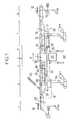
- the transfer assembly of this device is designed to take the sheaths, twenty-four for example, placed on a deposit rack 10 ( Figure 1) by a handling machine, arranged with a determined pitch, to bring them at the various locations where the necessary successive operations are carried out and finally transfer them to a recovery rack 12 in the form of a sheet at the same pace as on the removal rack. This sheet can thus be taken up by the same handling machine as that which was used for the removal.
- Units 7 and 8 have a constitution which is practically symmetrical to that of units 2 and 1 and will therefore not be described in detail.
- the deposit rack 10 occupies a fixed location in the direction of movement of the sheaths, indicated by the arrow F in FIGS. 1 and 2.
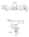
- the deposit rack 10 (FIGS. 3 and 4) consists of parallel plates 14 intended to support place the sheaths in place, only one of which 16 is shown in FIG. 4 in retaining meshes 18 at the step of removal by the handling machine. All the decks are identical. They are movable between a high position, in which they are shown in FIG. 1, and a low position where they are below the level of the belts 20 of the conveyor (unit 1) which will be described later.
- the vertical movement of the plates 14 between these two positions is controlled by a motor M 1 ( Figures 1 and 3). This motor drives a shaft 22 which carries operating cams 24.
- Each of these cams 24 cooperates with a push rod 26 which slides in a guide tube 28 of a support frame and the upper end of which is fixed to the plate.
- the guide of the plate provided by the push rod 26 is completed by the sliding of a vertical guide rod 30 in the chassis.
- the unit 1 (lateral transfer unit) comprises a conveyor comprising belts interposed between the plates 14 and having notches for receiving the sheaths distributed at the same pitch as the meshes 18 of the plates. All these belts 20 are designed to be simultaneously driven by an M2 motor. Going down the plates 14 previously loaded, the entire layer of sheaths is deposited on the conveyor and the actuation of the motor M2 allows continuous scrolling to completely release the sheaths by movement in the direction of arrow F, so that the station of deposit becomes free again.
- the unit 2 is intended to ensure a change of pitch necessary to present the sheaths one by one at a reading and weighing location.
- the size of the device intended to perform this function is not compatible with the compact arrangement of the sheaths desirable for transport by the handling machine.
- the step change unit 2 shown in Figures 1 and 2 is of the pilgrim's step type. It comprises several assemblies each comprising two fixed bars 32 and a movable bar 34.
- the driving member of the mechanism for driving the movable bars 34 is constituted by an M3 motor which drives, via chains 36, the keyed pulleys 38 on shafts 40.
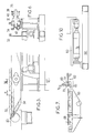
- Each shaft carries at the end two eccentric crank pins 42 (FIG. 6) mounted in the bearings of two corresponding movable bars 34.
- each revolution of the crank pin causes a cyclic displacement of the movable bar.
- the movable bars are placed relative to the unit 1 so that during their upward and forward movement the movable bars 34 take the closest sheath placed on the conveyor and advance it by an equal distance at the pitch p of notches provided on the fixed bars 32.
- the control of the motor M 2 is subject to a presence detector so that the belt conveyor 20 carries out an advance equal to one step, or to a multiple of steps if the tablecloth is incomplete, while unit 2 advances by one step p the sheath which has just been entered. This operation is repetitive, so that at each revolution of the eccentric crank pin 42, the unit 2 grasps a new sheath while, simultaneously, the series of previous ones is transferred by a notch to the fixed bars 32.
- One of the meshes of the fixed bars 32 (the fifth in FIG. 1) is replaced by a reading device making it possible to record the reference carried by the sheath, and weighing.
- This device may include conventional optical elements and an electronic balance from commonly available components so that it is not necessary to describe it in detail.
- the unit 3 intended to effect a second change of pitch, so as to reduce this pitch to a value equal to that of the machine presenting the pellets at the end of the vibrating table, is also of the mit pitch type.
- This unit also comprises bars 46 having an unchanging height and which will therefore be called “fixed” bars and mobile bars 38 having a cyclic movement also controlled by the motor M3 which ensures absolute synchronism between the second and the third unit.
- the control rods of the bars 48 have an eccentricity such that they keep a different pitch from that of the control rods of the bars 34.
- the eccentricity can be for example 10 mm instead of 20 mm, the mesh pitch of the bars 46 being 20 mm instead of 40 mm.
- Unit 4 ensuring the supply of the vibrating table 50 with sheaths and the evacuation of the sheaths after filling, is combined with units 3 and 6.
- the fixed bars 46 of unit 3 are in fact integral with bars 52 having the same mesh pitch, placed downstream of the bars 46 in the direction of flow (arrow F).
- a drive mechanism makes it possible to longitudinally move all of the fixed bars 46 and 52 from the position shown in solid lines in FIG. 1 to the position shown in dashes after erasing, using the jacks 82, of the sheath supports carried by the vibrating table.
- the amplitude of this movement is such that the sheaths carried by the bars 46 come to a position of engagement by a feed mechanism of the vibrating table 50 and the already filled sheaths, carried by the bars 52, come in the position of evacuation.
- the number of meshes of the bars 46 and 52 will be fixed by the number of sheaths that the vibrating table 50 can simultaneously supply. In FIG. 9, it has been assumed, by way of example, bars with twenty-four meshes.
- the longitudinal movement mechanism of the bars 46-52 can be very variable in nature.
- the mechanism shown by way of example in FIG. 1 comprises a jack V, the piston rod of which is coupled to a double idler gear 54 which drives two fixed racks and two racks 56 secured to a carriage carrying the bars 46 and 52
- the actuator is provided with two corresponding limit switches 58, one at the position of the carriage shown in FIG. 1 in solid lines, the other at the position shown in dashes.
- the unit 5 located at the end of the vibrating table 50 but opposite the arrival of the pellets, has the function of ensuring indexing, that is to say the precise axial alignment and the maintenance of the sheaths before resumption of maintenance and level by the clean devices of the vibrating table and, subsequently, after pelletizing, the reverse maneuver of disengagement (de-indexing) of the sheaths with a view to their removal by the unit 4.
- the movable assembly comprises a chassis 60 provided with slides allowing it to slide on two axes 61 parallel to the axis of the sheaths, carried by a base 62 itself mobile along the same axis to adapt to two lengths of sheaths.
- a jack V2 mounted between the chassis 60 and the base 62 (FIG. 10) makes it possible to advance the chassis on the axes 61 from the position where it is shown in FIG. 7.
- the chassis 60 carries spring rods 64 (FIG. 8) in a number equal to that of the ducts and at the same spacing. It also carries coaxial input rollers 66 having guide grooves having the same spacing as the sheaths.
- the stroke of the cylinder V2 is such that the advancement of the chassis 60 under the action of this cylinder causes the rods 64 to come into abutment in the indexing noses 68 carried by the vibrating table 50, the insertion of the rods 64 into the chassis 60 and the compression of the rod springs.
- the chassis 60 carries a vertical cylinder V3, the rod of which ends in a bar 70 intended to press the sheaths 16 against the rollers 66 and to hold them in position before resumption of maintenance by holding devices associated with the vibrating table 50 and not shown.
- the vibrating table is provided with means, constituted by jacks 82 in FIG. 1, making it possible to bring it to the two levels designated by N1 and N2 in FIG. 8, corresponding respectively to the indexing and to the filling in fuel pellets, and escape down below the NO level to allow transfer by unit 4.
- the unit 6, intended to bring the sheaths to a spacing allowing cleaning of the sheath end by passing a flock, has a constitution similar to that of the unit 3. It includes a set of movable bars 72 actuated from an M4 engine via pulleys and chains.
- the unit 7 similar in constitution to that of the unit 2, also includes fixed bars 74 and movable bars 76. The latter are also driven by the motor M4, in synchronism with the bars 72.
- the unit 7 allows cleaning and continuous transfer of the series of sheaths to the conveyor 87, symmetrical to the conveyor 20 and actuated by a motor M 5, and at the same pace as during removal.
- transporter 78 which constitutes the unit 8, cooperates with the recovery rack 12, actuated by an M6 motor.
- the transfer assembly can be complete by means allowing it to accept several lengths of sheaths.
- these complementary means comprise a jack V5 which, before the weighing operation, realigns each sheath as it comes before the jack.
- These means also include a mechanism (not shown) making it possible to give the base 62 of the chassis 60 (FIG. 7) different positions depending on the length of the sheaths to be treated. As a general rule, moreover, the number of lengths to be treated will be small and will not exceed two.
- the transfer assembly is associated with means for automatic synchronized control of all of the drive members, which may be constituted by a programmable automaton associated with a power cabinet. It is not necessary to describe here the constitution and the programming of the PLC because they follow directly from the sequence of operations to be performed, which will now be summarized.
- a sheet of sheaths closed at one end is placed on the rack 10 when the sequence of operations begins.
- the rack 10 is then lowered using the motor Ml, which rests the sheaths on the meshes of the conveyor 20.
- the motor M2 is actuated to move the conveyor 20 over a sufficient length to completely clear the sheaths of the rack 10. It then becomes free and can be returned to the initial position, awaiting a new layer of sheaths.
- the motor M2 of the conveyor 20 and the motor M3 actuated at the same time then intervene, with continuous operation, to cause the loading of the series of sheaths on the unit 2, with change of pitch.
- This unit 2 makes it possible to form, from a sheet with a tight pitch to reduce its bulk during handling, a sheet with a wide pitch leaving the required space for the reading and weighing device.
- the motor M3 actuates the unit 3 so that the sheaths arriving at the end of the unit 2 undergo a new change of pitch, which brings them back to a compact position compatible with the loading pitch.
- all the sheaths are on the fixed bars 46.
- the actuation of the jack V 1 brings the bars 46 back to- above the vibrating table machine 50 and, simultaneously, brings the previously loaded sheaths above the bars 72 of the unit 6, intended to effect a new change of pitch.
- the lifting means of the vibrating table shown diagrammatically in FIG. 1 by jacks 82, have previously cleared the sheaths of the holding devices associated with the vibrating table 50.
- the ascent of the table 50 to level N2 authorizes that the means of indexing then intervenes and push the sheaths into the indexing noses 68, so as to ensure precise positioning of the sheaths in front of the pellet supply corridors.
- the deindexing is then carried out by unit 5 after returning from the vibrating table at level N 1 and advanced of chassis 60 and combined action of cylinders V2 and V3. It is unnecessary to describe the sequence of operations, symmetrical to those carried out upstream of the vibrating table loading machine. It suffices to note that a cleaning of the terminal parts of the sheaths, in order to remove the fuel powder, is carried out using fluff in the zone indicated by 6 in FIG. 1, during the continuous scrolling on the fixed bars 74.
Landscapes
- Engineering & Computer Science (AREA)
- Physics & Mathematics (AREA)
- Plasma & Fusion (AREA)
- General Engineering & Computer Science (AREA)
- High Energy & Nuclear Physics (AREA)
- Manufacturing & Machinery (AREA)
- Monitoring And Testing Of Nuclear Reactors (AREA)
- Rigid Pipes And Flexible Pipes (AREA)
- Branching, Merging, And Special Transfer Between Conveyors (AREA)
Claims (9)
Applications Claiming Priority (2)
| Application Number | Priority Date | Filing Date | Title |
|---|---|---|---|
| FR8321125A FR2557723B1 (fr) | 1983-12-30 | 1983-12-30 | Dispositif de transfert de gaines d'elements de combustible nucleaire a un poste fixe de remplissage en pastilles |
| FR8321125 | 1983-12-30 |
Publications (3)
| Publication Number | Publication Date |
|---|---|
| EP0148091A2 EP0148091A2 (de) | 1985-07-10 |
| EP0148091A3 EP0148091A3 (en) | 1985-08-07 |
| EP0148091B1 true EP0148091B1 (de) | 1987-06-24 |
Family
ID=9295768
Family Applications (1)
| Application Number | Title | Priority Date | Filing Date |
|---|---|---|---|
| EP84402751A Expired EP0148091B1 (de) | 1983-12-30 | 1984-12-28 | Vorrichtung zum Transferieren von Kernbrennstoffhüllen in einer festen Tablettenfüllungsstation |
Country Status (9)
| Country | Link |
|---|---|
| US (1) | US4680920A (de) |
| EP (1) | EP0148091B1 (de) |
| JP (1) | JPS60158393A (de) |
| KR (1) | KR850004694A (de) |
| DE (1) | DE3464432D1 (de) |
| ES (1) | ES8701419A1 (de) |
| FR (1) | FR2557723B1 (de) |
| YU (1) | YU285A (de) |
| ZA (1) | ZA8410133B (de) |
Families Citing this family (7)
| Publication number | Priority date | Publication date | Assignee | Title |
|---|---|---|---|---|
| US4849156A (en) * | 1987-07-10 | 1989-07-18 | United Kingdom Atomic Energy Authority | Nuclear fuel pin fabrication |
| US4980119A (en) * | 1989-04-04 | 1990-12-25 | General Electric Company | Multizone automated nuclear fuel rod loading system |
| US4982556A (en) * | 1989-05-09 | 1991-01-08 | Tisma Machine Corporation | Modularly constructed automatic packaging machine |
| JP2567269Y2 (ja) * | 1991-07-01 | 1998-04-02 | 近畿車輌株式会社 | ゴルフ練習場の制御システム |
| IT1260469B (it) * | 1992-05-27 | 1996-04-09 | Macchina inscatolatrice per fiale in particolare del tipo in vetro ad uso medico | |
| US7593501B2 (en) * | 2005-01-06 | 2009-09-22 | Areva Np Inc. | Segment make-up system and method for manufacturing nuclear fuel rods |
| JP6564426B2 (ja) * | 2017-07-07 | 2019-08-21 | ファナック株式会社 | 部品供給装置及び機械学習装置 |
Family Cites Families (10)
| Publication number | Priority date | Publication date | Assignee | Title |
|---|---|---|---|---|
| US1775121A (en) * | 1926-05-11 | 1930-09-09 | French & Hecht Inc | Means for conveying articles |
| US2567488A (en) * | 1943-07-15 | 1951-09-11 | Autopack London Ltd | Reciprocating pusher conveyer |
| CH462382A (de) * | 1966-08-06 | 1968-09-15 | Ejectoret Sa | Einrichtung zum Abfüllen strömungsfähiger Medien in Behälter |
| JPS4918071B1 (de) * | 1967-03-23 | 1974-05-07 | ||
| GB1214725A (en) * | 1968-08-14 | 1970-12-02 | Ass Elect Ind | Improvements relating to mechanical handling apparatus |
| DE2005389A1 (en) * | 1970-02-06 | 1971-08-19 | Siemens Ag | Transport trolley for fuel element sheath tub |
| US3815726A (en) * | 1970-04-06 | 1974-06-11 | Mark V Automation Ltd | Conveyor |
| US3965648A (en) * | 1974-01-03 | 1976-06-29 | Westinghouse Electric Corporation | Apparatus for loading fuel pellets in fuel rods |
| JPS5357674A (en) * | 1976-11-02 | 1978-05-25 | Yoshida Kogyo Kk | Element feeder |
| US4505373A (en) * | 1982-07-01 | 1985-03-19 | Diamond Automations, Inc. | Egg transfer system |
-
1983
- 1983-12-30 FR FR8321125A patent/FR2557723B1/fr not_active Expired
-
1984
- 1984-12-28 DE DE8484402751T patent/DE3464432D1/de not_active Expired
- 1984-12-28 ZA ZA8410133A patent/ZA8410133B/xx unknown
- 1984-12-28 EP EP84402751A patent/EP0148091B1/de not_active Expired
- 1984-12-28 ES ES539534A patent/ES8701419A1/es not_active Expired
- 1984-12-28 US US06/687,228 patent/US4680920A/en not_active Expired - Fee Related
- 1984-12-28 JP JP59281843A patent/JPS60158393A/ja active Pending
- 1984-12-29 KR KR1019840008549A patent/KR850004694A/ko not_active Withdrawn
-
1985
- 1985-01-03 YU YU00002/85A patent/YU285A/xx unknown
Also Published As
| Publication number | Publication date |
|---|---|
| YU285A (en) | 1991-01-28 |
| JPS60158393A (ja) | 1985-08-19 |
| KR850004694A (ko) | 1985-07-25 |
| EP0148091A3 (en) | 1985-08-07 |
| EP0148091A2 (de) | 1985-07-10 |
| ES539534A0 (es) | 1986-12-01 |
| FR2557723A1 (fr) | 1985-07-05 |
| ZA8410133B (en) | 1986-02-26 |
| US4680920A (en) | 1987-07-21 |
| FR2557723B1 (fr) | 1986-05-30 |
| DE3464432D1 (en) | 1987-07-30 |
| ES8701419A1 (es) | 1986-12-01 |
Similar Documents
| Publication | Publication Date | Title |
|---|---|---|
| US6881048B1 (en) | Apparatus for automatically loading powder material into a mold | |
| US4264253A (en) | Method and apparatus for forming a lumber stack and placing sticks between adjacent courses in the stack | |
| US4468163A (en) | Tray loader method and apparatus for nuclear fuel pellets | |
| FR2475785A1 (fr) | Appareil de chargement de barreaux de combustible pour un reacteur nucleaire | |
| EP0243236A1 (de) | Vorrichtung zum Überbringen von Gegenständen, insbesondere Glasplatten | |
| EP0148091A2 (de) | Vorrichtung zum Transferieren von Kernbrennstoffhüllen in einer festen Tablettenfüllungsstation | |
| EP0229788A1 (de) | Modular aufbebaute installation zum kontrollierten transport von teilen oder erzeugnissen. | |
| JP2510026B2 (ja) | 燃料ペレットを被覆管に装填する自動システム | |
| US4629138A (en) | Apparatus for feeding and discharging reels from a machine for winding video tape on reels of a cassette | |
| US4980119A (en) | Multizone automated nuclear fuel rod loading system | |
| FR2559138A1 (fr) | Procede et appareillage de manutention rapide d'articles dans une installation de stockage | |
| CH620170A5 (de) | ||
| FR2520183A1 (fr) | Machine de chargement et de dechargement automatiques de plaquettes de circuits imprimes pour machine d'insertion de composants electroniques | |
| EP0286546B1 (de) | Fertigungssystem mit einer schnellen Vorrichtung zum Zuführen und Positionieren mit rechteckiger Bewegung | |
| EP0605316A1 (de) | Verfahren und Vorrichtung zur automatischen Sortierung von Kernbrennstofftabletten | |
| EP0617691B1 (de) | Verfahren und vorrichtung zum bewegen von gegenständen um eine bahn und verwendung der vorrichtung | |
| CN113001179A (zh) | 全自动牙箱与轴承座组装设备及方法 | |
| EP0091421A1 (de) | Verfahren und Vorrichtung zum Behandeln von Gegenständen | |
| CA2695392A1 (fr) | Systeme de depose de documents dans des caisses | |
| US3599396A (en) | Apparatus for packing rod-shaped objects in containers | |
| US3080070A (en) | Methods of and means for the stacking of articles into layers | |
| EP0419376B1 (de) | Fertigungseinrichtung mit einer Vorrichtung zum schnellen Zuführen und Positionieren im doppelten Pilgerschritt und Fertigungssystem zum Verwenden dieser Einrichtung | |
| JP3197688B2 (ja) | 溝形鋼の自動積重ね装置 | |
| CN116461966A (zh) | 一种料盘分检的输送机构及系统 | |
| GB2092091A (en) | Apparatus for stacking elongate elements such as sections or bars |
Legal Events
| Date | Code | Title | Description |
|---|---|---|---|
| PUAI | Public reference made under article 153(3) epc to a published international application that has entered the european phase |
Free format text: ORIGINAL CODE: 0009012 |
|
| PUAL | Search report despatched |
Free format text: ORIGINAL CODE: 0009013 |
|
| AK | Designated contracting states |
Kind code of ref document: A2 Designated state(s): BE DE GB IT SE |
|
| AK | Designated contracting states |
Kind code of ref document: A3 Designated state(s): BE DE GB IT SE |
|
| 17P | Request for examination filed |
Effective date: 19850713 |
|
| 17Q | First examination report despatched |
Effective date: 19860909 |
|
| GRAA | (expected) grant |
Free format text: ORIGINAL CODE: 0009210 |
|
| AK | Designated contracting states |
Kind code of ref document: B1 Designated state(s): BE DE GB IT SE |
|
| PG25 | Lapsed in a contracting state [announced via postgrant information from national office to epo] |
Ref country code: IT Free format text: LAPSE BECAUSE OF FAILURE TO SUBMIT A TRANSLATION OF THE DESCRIPTION OR TO PAY THE FEE WITHIN THE PRESCRIBED TIME-LIMIT;WARNING: LAPSES OF ITALIAN PATENTS WITH EFFECTIVE DATE BEFORE 2007 MAY HAVE OCCURRED AT ANY TIME BEFORE 2007. THE CORRECT EFFECTIVE DATE MAY BE DIFFERENT FROM THE ONE RECORDED. Effective date: 19870624 |
|
| REF | Corresponds to: |
Ref document number: 3464432 Country of ref document: DE Date of ref document: 19870730 |
|
| PLBE | No opposition filed within time limit |
Free format text: ORIGINAL CODE: 0009261 |
|
| STAA | Information on the status of an ep patent application or granted ep patent |
Free format text: STATUS: NO OPPOSITION FILED WITHIN TIME LIMIT |
|
| 26N | No opposition filed | ||
| PGFP | Annual fee paid to national office [announced via postgrant information from national office to epo] |
Ref country code: DE Payment date: 19931201 Year of fee payment: 10 |
|
| PGFP | Annual fee paid to national office [announced via postgrant information from national office to epo] |
Ref country code: SE Payment date: 19931216 Year of fee payment: 10 |
|
| PGFP | Annual fee paid to national office [announced via postgrant information from national office to epo] |
Ref country code: GB Payment date: 19931221 Year of fee payment: 10 |
|
| PGFP | Annual fee paid to national office [announced via postgrant information from national office to epo] |
Ref country code: BE Payment date: 19931222 Year of fee payment: 10 |
|
| PG25 | Lapsed in a contracting state [announced via postgrant information from national office to epo] |
Ref country code: GB Effective date: 19941228 |
|
| PG25 | Lapsed in a contracting state [announced via postgrant information from national office to epo] |
Ref country code: SE Effective date: 19941229 |
|
| PG25 | Lapsed in a contracting state [announced via postgrant information from national office to epo] |
Ref country code: BE Effective date: 19941231 |
|
| EAL | Se: european patent in force in sweden |
Ref document number: 84402751.6 |
|
| BERE | Be: lapsed |
Owner name: SOC. COGEMA FRAMATOME ET URANIUM PECHINEY Effective date: 19941231 |
|
| GBPC | Gb: european patent ceased through non-payment of renewal fee |
Effective date: 19941228 |
|
| PG25 | Lapsed in a contracting state [announced via postgrant information from national office to epo] |
Ref country code: DE Effective date: 19950901 |
|
| EUG | Se: european patent has lapsed |
Ref document number: 84402751.6 |