EP0286546B1 - Fertigungssystem mit einer schnellen Vorrichtung zum Zuführen und Positionieren mit rechteckiger Bewegung - Google Patents
Fertigungssystem mit einer schnellen Vorrichtung zum Zuführen und Positionieren mit rechteckiger Bewegung Download PDFInfo
- Publication number
- EP0286546B1 EP0286546B1 EP19880420075 EP88420075A EP0286546B1 EP 0286546 B1 EP0286546 B1 EP 0286546B1 EP 19880420075 EP19880420075 EP 19880420075 EP 88420075 A EP88420075 A EP 88420075A EP 0286546 B1 EP0286546 B1 EP 0286546B1
- Authority
- EP
- European Patent Office
- Prior art keywords
- product
- vertical
- conveyor
- horizontal
- cycle
- Prior art date
- Legal status (The legal status is an assumption and is not a legal conclusion. Google has not performed a legal analysis and makes no representation as to the accuracy of the status listed.)
- Expired - Lifetime
Links
Images






Classifications
-
- B—PERFORMING OPERATIONS; TRANSPORTING
- B23—MACHINE TOOLS; METAL-WORKING NOT OTHERWISE PROVIDED FOR
- B23Q—DETAILS, COMPONENTS, OR ACCESSORIES FOR MACHINE TOOLS, e.g. ARRANGEMENTS FOR COPYING OR CONTROLLING; MACHINE TOOLS IN GENERAL CHARACTERISED BY THE CONSTRUCTION OF PARTICULAR DETAILS OR COMPONENTS; COMBINATIONS OR ASSOCIATIONS OF METAL-WORKING MACHINES, NOT DIRECTED TO A PARTICULAR RESULT
- B23Q7/00—Arrangements for handling work specially combined with or arranged in, or specially adapted for use in connection with, machine tools, e.g. for conveying, loading, positioning, discharging, sorting
- B23Q7/003—Cyclically moving conveyors
-
- B—PERFORMING OPERATIONS; TRANSPORTING
- B23—MACHINE TOOLS; METAL-WORKING NOT OTHERWISE PROVIDED FOR
- B23P—METAL-WORKING NOT OTHERWISE PROVIDED FOR; COMBINED OPERATIONS; UNIVERSAL MACHINE TOOLS
- B23P21/00—Machines for assembling a multiplicity of different parts to compose units, with or without preceding or subsequent working of such parts, e.g. with program control
- B23P21/004—Machines for assembling a multiplicity of different parts to compose units, with or without preceding or subsequent working of such parts, e.g. with program control the units passing two or more work-stations whilst being composed
-
- B—PERFORMING OPERATIONS; TRANSPORTING
- B23—MACHINE TOOLS; METAL-WORKING NOT OTHERWISE PROVIDED FOR
- B23Q—DETAILS, COMPONENTS, OR ACCESSORIES FOR MACHINE TOOLS, e.g. ARRANGEMENTS FOR COPYING OR CONTROLLING; MACHINE TOOLS IN GENERAL CHARACTERISED BY THE CONSTRUCTION OF PARTICULAR DETAILS OR COMPONENTS; COMBINATIONS OR ASSOCIATIONS OF METAL-WORKING MACHINES, NOT DIRECTED TO A PARTICULAR RESULT
- B23Q7/00—Arrangements for handling work specially combined with or arranged in, or specially adapted for use in connection with, machine tools, e.g. for conveying, loading, positioning, discharging, sorting
- B23Q7/14—Arrangements for handling work specially combined with or arranged in, or specially adapted for use in connection with, machine tools, e.g. for conveying, loading, positioning, discharging, sorting co-ordinated in production lines
- B23Q7/1426—Arrangements for handling work specially combined with or arranged in, or specially adapted for use in connection with, machine tools, e.g. for conveying, loading, positioning, discharging, sorting co-ordinated in production lines with work holders not rigidly fixed to the transport devices
- B23Q7/1478—Arrangements for handling work specially combined with or arranged in, or specially adapted for use in connection with, machine tools, e.g. for conveying, loading, positioning, discharging, sorting co-ordinated in production lines with work holders not rigidly fixed to the transport devices using a conveyor comprising cyclically-moving means
- B23Q7/1484—Arrangements for handling work specially combined with or arranged in, or specially adapted for use in connection with, machine tools, e.g. for conveying, loading, positioning, discharging, sorting co-ordinated in production lines with work holders not rigidly fixed to the transport devices using a conveyor comprising cyclically-moving means with carrier means
-
- G—PHYSICS
- G05—CONTROLLING; REGULATING
- G05B—CONTROL OR REGULATING SYSTEMS IN GENERAL; FUNCTIONAL ELEMENTS OF SUCH SYSTEMS; MONITORING OR TESTING ARRANGEMENTS FOR SUCH SYSTEMS OR ELEMENTS
- G05B19/00—Program-control systems
- G05B19/02—Program-control systems electric
- G05B19/04—Program control other than numerical control, i.e. in sequence controllers or logic controllers
- G05B19/12—Program control other than numerical control, i.e. in sequence controllers or logic controllers using record carriers
- G05B19/128—Program control other than numerical control, i.e. in sequence controllers or logic controllers using record carriers the workpiece itself serves as a record carrier, e.g. by its form, by marks or codes on it
Definitions
- the invention relates to a production system with a rapid device for feeding, positioning and removing products for automated equipment served by free transfer conveyors, in particular an upstream conveyor and a downstream conveyor, between which is inserted.
- said feeding, positioning and removal device which comprises a mobile support actuated by an actuating mechanism with an electric drive motor, for carrying out a rectangular cycle with pilgrim steps, comprising a vertical support stroke of the product to be treated, brought at a random rate by the upstream conveyor, a horizontal stroke for bringing the product, a vertical stroke for positioning the product in a predetermined treatment location and a horizontal return stroke, said actuation mechanism comprising cams for transforming the rotary movement of the motor into linear movements corresponding to said travel s vertical and horizontal, said system further comprising several handling devices for carrying out insertions, operations or treatments on the product positioned by said feeding, positioning and removal device, successively opposite said handling devices.
- the object of the present invention is to allow the production of a production system operating at high rates and having great flexibility.
- cam manipulator allows an improvement in the speed of the assembly, and by providing a mechanical separation between the cam mechanism of the feed device and the cam mechanisms of the manipulators it is possible to adapt quickly the operation of each manipulator to the type of product manufactured, and to ensure great flexibility.
- the electrical or electronic control system ensures synchronization of the various mechanisms.
- the mobile support with crawl steps simultaneously performs the operation of feeding a product to be treated and the operation of removing a treated product, the latter being deposited on the downstream conveyor.
- the mobile support is driven by cams controlled by a single motor which controls the vertical movements and the horizontal movements. Synchronization is carried out by the usual techniques well known to specialists.
- the rectangular cycle of the mobile support has a waiting position, in which the movement stops if the supply of a new pallet by the upstream conveyor has not been made in due time. This waiting position corresponds to the entry point of the system and the start of the cycle is for example controlled by a detector of the presence of a product at the pick-up location.
- the manipulator is synchronized with the feed and positioning device, by electrical or electronic means well known to specialists.
- the electrical synchronization between the feed device and the manipulation device (s) makes it possible to avoid the obligation to operate all of these devices systematically simultaneously and to produce a flexible assembly station.
- the need for flexibility is reflected in the fact that the pallets presented on the supply conveyor can carry different products, or different variants of a product, which amounts to the same thing, and that the treatment must be adapted to the type. of product.
- the system for controlling the operation of each handling device is arranged to control the operation of the handling device when a product or a pallet carrying the product comes before it, only if the product variant relates said handling device.
- the pallets, or the products themselves, carry a coding allowing the automatic identification of the product or the variant by a sensor of a type known per se, placed upstream of the station.
- a sensor of a type known per se placed upstream of the station.
- any variant identified is advantageously stored in the control system of the assembly, for example a programmable controller, and this variant can be followed during its passage through the n positions of the feeding device, and does not trigger at the desired time that the handling device which concerns it, the others being left at rest when said variant is presented before them.
- a flexible system is thus produced, insofar as each variant receives the specific treatment which it requires, and this without it being necessary to make any modification or adjustment of the system.
- a more complex use of a device with n manipulators is possible by mixing the two possibilities available, in this case, performing several successive operations on the same product and performing different operations on different products.
- the total duration of the vertical strokes can also be significantly increased, which opens up interesting possibilities for configuring the space-time diagram of these strokes, by obtaining longer intermediate phases, therefore having a slower speed, this while respecting acceptable accelerations and decelerations.
- a product 1 is positioned on a tool or a pallet 2 transported by a conveyor 3, for example constituted by two belts 4,5 parallel and driven in synchronism by a suitable motor.
- the conveyor cooperates with a device designated by the general reference 6, for feeding, positioning and removing the product 1 from a work station equipped with a manipulator 9.
- the device 6 supports the pallet 2 in one predetermined location 7, defined by a stop 15 interfering with the conveyor 3, and brings it into a working position 10 previously occupied by the pallet 2 ′.
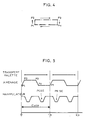
- a mobile support 11 animated by a movement of the pilgrim's step type constituted by a rectangular cycle, represented diagrammatically in FIG. 4.
- the points P1, P2, P3, P4, are the four vertices of the cycle , between which the movements, of rectilinear type, are: P1 P2: climb; P2 P3: feed - transfer; P3 P4: descent; P4 P1: return.
- the mobile support 11 animated by this cycle is a block actuated by a mechanical device (not shown), contained in a chassis 12, and driven by a motor 13.
- the mechanical device preferably is with two cams, of a type known per se, and the details of which will not be reproduced here.
- the manipulator 9 also includes cams and a motor 14 for actuation.
- the essential difference between the two devices lies in the cycle, which is of the closed rectangular type for the supply, and of the inverted U type for the manipulator 9 which takes the component 8 of a supply device 19 to deposit it on the product 1.
- the mobile support 11 carries pins 17 ′, 17 ⁇ ; 18,18 capable of penetrating into conjugate holes 20 of pallets 2 for centering and positioning the latter on the support 11.
- the length of the mobile support 11 corresponds to the distance between the position of support 7 and the position of work 10 , so as to cooperate simultaneously with two pallets 2,2 ′.
- the working position 10 is defined by two longitudinal members 16,16 ′ which frame the belts 4,5 and on which the pallet 2 ′ is placed (for clarity of the drawings, the longitudinal member 16 ′ is not shown in FIGS. 1 and 3).
- the upper bearing face of the longitudinal members 16,16 ′ is higher than the belts 4,5 and it carries pins 21 which penetrate with slight play in conjugated holes 22 of the pallet 2 ′ to position the latter.
- the device works as follows:
- the conveyor 3 is interposed between the side members 16.16 ′ and the block 11 passes between the two belts 4,5 of the conveyor, but it is clear that any other arrangement can be envisaged without departing from the scope of the invention, for example it is possible to interrupt the conveyor 3 by dividing it into an upstream section and a downstream section, with idler pulleys es of both sides of the fixed support consisting of rails 16,16. We thus avoid the coexistence in the same area of this support 16,16 ′ of block 11, and of the conveyor 3, the latter having no utility in this area. It is also possible to limit the conveyor 3 to a reduced section corresponding substantially to the width of the chassis 12, this section connecting upstream and downstream to another type of conveyor. This solution has the advantage of being able to choose for the transfer between stations another type of conveyor than that serving the station itself, which imposes fewer constraints on the designer.
- the system is then examined from the angle of synchronization.
- the estimated duration of this transfer is 0.6s, corresponding to a conveyor speed of 10 m / min and a displacement of 100 mm equal to the length of the pallet .
- the duration of the cycle is conditioned by the supply which at a period of 1s and when the block 11 returns to the initial position P1, the new pallet 2 ′′′ is already in abutment from 0 , 15.
- the feed mechanism will therefore not have to stop, in accordance with what has been said above.
- manipulator-feed synchronization can be carried out by known electrical means.
- the manipulator and the feed are for example each equipped with a stepping motor or a DC motor associated with position encoders. With certain precautions the use of AC motors can also be considered.
- the electrical solution has the advantage of eliminating the mechanical connection between the 2 devices, which become physically distinct components.
- One of the devices can be in motion while the other remains stationary and it is possible to operate several manipulators on a single feed, the latter serving several successive work points without intermediate removal on the conveyor, in the same way as '' a rigid transfer.
- the waiting position of the feed being P1 that of the manipulator will be a position located somewhere on the return stroke.
- this waiting position allows the system to come to a standstill after taking over a pallet, if the next one does not arrive immediately.
- a similar problem cannot be excluded on the side of the distribution of components 8. Indeed, if after removing one component it is not replaced by another within a normal period, the system has an interest in staying in standby until power is restored. It would be pointless to bring a pallet into the working position if there is no component to bring it.
- a movable block 11 which is elongated and has seven pallet locations 2, which means that the maximum number of workstations that can be served is six.
- Block 11 is shown in the downstream position of the pilgrim's cycle.
- the length of the fixed supports 16, 16 ′ corresponds to the number of said working positions, numbered from P1 to P6.
- a handling device 9.1 to 9.6 Next to each working position is arranged a handling device 9.1 to 9.6. It should be noted that these handling devices or apparatus must fit into a width less than the pitch of the feeding device, which explains the arrangement in the vertical plane of their drive motors 14.1 to 14.6. For clarity of the drawing, only the handling device 9.3 is shown in full, the other five being shown partially.
- a pallet 2 carrying a type of product 1 to be treated is shown, in the standby position adjacent to the station P1, ready to be supported by the movable block 11 during the pilgrim step cycle.
- Each handling device 9.1 to 9.6 is associated with a feeding device, represented by bowls vibrators 25.1 to 25.6 extended by rails 26.1 to 26.6 allowing the components to be inserted to be taken into position.
- a feeding device represented by bowls vibrators 25.1 to 25.6 extended by rails 26.1 to 26.6 allowing the components to be inserted to be taken into position.
- three of the rails 26.1 to 26.3 have been placed longitudinally, and three others 26.4 to 26.6 transversely relative to the manipulators 9.1 to 9.6.
- any other type of distribution system or any other arrangement can be envisaged without departing from the scope of the invention.
- a sensor 27, placed opposite the pallet 2 in the standby position, is designed to identify the variant carried by the pallet.
- the sensor 27, for example optical, reads a code carried by the product 1 or the pallet 2 and sends its information to the device for controlling the assembly, which can be a programmable controller (not shown).
- This automaton receives the other data, in particular of the position of the block 11, of the presence of a pallet 2 and of the components to be inserted and in turn sends operating orders in due time to the various manipulators 9.1 9.6.
- the device according to FIG. 6 can treat six variants 1.1 to 1.6 of product.
- the variant 1.1 is for example processed at the workstation P1, the programmable controller controlling the handling device 9.1 in the first cycle of pilgrim feeding from the block 11, bringing the product 1.1 to the location P1.
- the other handling devices 9.2 to 9.6 remain inactive when the product 1.1 subsequently comes to their workstations P2 to P6.
- the control system will react by sending to it a pulse allowing it to carry out a cycle when the pallet 2 will appear before him.
- the other manipulators remain inactive when passing this pallet.
- variant 1.1 receives two successive treatments, these will be carried out by two handling devices, for example 9.1 and 9.2 or any other combination.
- the number of workstations will of course have to be adapted to the number of operations and the number of variants.
- the mounting plane of the support 16 must be slightly raised relative to the conveyor 3 to avoid inadvertent contact of the latter with the pallet (s) in the working position.
- This offset would be useless either if the conveyor was interrupted in the work area, i.e. if there were two separate conveyors for supply and evacuation, or if the conveyor was simply lowered in the work area , for example by an appropriate set of deflection pulleys.
- the solutions involve a slight complementary mechanical complexity, but which can be justified insofar as the elimination of the offset allows a significant complementary improvement of the space-time diagram. With reference to FIG. 5 in which, for example, the equipment cycle has been taken equal to one second, it appears that an optimization of the cycle can be obtained by an appropriate distribution of this cycle between the four pre-described phases of the rectangular layout cycle.
- the first constraint to be satisfied is to allow the active device time to carry out its intervention, in this case the laying operation if it is an insertion manipulator.
- this intervention must be done during phase P4 ⁇ P1 which corresponds to the empty return of the mobile support while the pallet 2 is in the working position.
- the phase P4 ⁇ P1 must therefore not be too short.
- the remaining time (from P1 to P4) is best distributed between the ascent, transfer and descent. If we consider that the horizontal stroke "a" is significantly larger than the vertical stroke "h”, it seems logical to allocate much more time to the transfer than to the ascent and the descent.
- the present invention is based on the observation that it is during the ascent and descent that one meets the most dangerous shocks and vertical accelerations for the holding of the product and the invention consists in favoring the movements of up and down.
- Figure 8 shows the silhouettes of pawns 17 and 21, with their engagement in the pallets. A greater clearance is provided between the pallet and the pin 17, this to avoid that the guide of the pins 17, 17 ′ does not interfere with that of the pins 21, 21 ′ when the pallets are deposited on the support 16, the best precision being of course reserved for the pins 21, 21 ′.
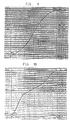
- FIG. 9 represents the space-time diagram of the mobile 11 during its climb stroke P1 ⁇ P2 in usual operation.
- the points M1 and M2 correspond respectively to the positions P1 and P2 of the mobile, M1 being taken conventionally as the origin of the coordinates.
- the acceleration is very moderate.
- the impact speeds are high, owing to the fact that the planes 102 and 103 are located not far from mid-course. This can cause fear of dangerous shock effects for the stability of the product.
- FIG. 10 An improvement according to the invention is represented by FIG. 10.
- a zone at reduced speed appears in the vicinity of the planes 102 and 103.
- this area has been extended slightly on both sides of planes 102 and 103, to take account of possible inaccuracies (0.5 mm on each side).
- FIG. 11 A second level of improvement is shown in FIG. 11.
- the vertical stroke of the mobile has been increased by 2 mm upwards and by 2 mm downwards, these complementary strokes being carried out before and after the 0.15 s theoretical time slot.
- the points M1 and M2 have not changed, the useful vertical travel, that is to say interesting for the planes between 101 and 104, appears as before.
- the increase in the total vertical stroke both in time and in space makes it possible to widen the range at reduced speed, while better controlling the accelerations.
- FIG. 11 a representation of what an optimized space-time diagram could be in the case where the offset between the planes of the conveyor 102 and the fixed support 103 is eliminated.
- the zone at moderate speed can then be limited to the imprecision range, which can be estimated at around 1 mm.
- the accelerations are not modified, we arrive at the dotted diagram which shows an even reduced impact speed, namely around 0.015 m / s, a figure which could be further reduced by better control of the general precision of the system. .
- the horizontal movements can, at first analysis, be limited to the theoretical slots of 0.35 s. In the case of FIGS. 9 and 10, there is then a perfect succession of the four movements, without any overlap.
- the cycle is perfectly rectangular. In the case of Figure 11, on the other hand, there are overlap between the end of a vertical movement and the start of a horizontal movement. The cycle is no longer perfectly rectangular, but has rounded shapes as shown in FIG. 12. On the other hand, the points P1 - P2 - P3 - P4 are still respected.
- FIG. 11 bis which is a space-time curve of the end and the beginning of the horizontal movement, on either side of a vertical stroke.
- FIG. 11 bis which is a space-time curve of the end and the beginning of the horizontal movement, on either side of a vertical stroke.
- This diagram can be read with a time scale common to Figure 11. If we admit overlaps of 0.015 s, the time available for horizontal movement becomes 0.38 s, and the acceleration calculation gives 4.15 m / s2 (0.46 g).
Landscapes
- Engineering & Computer Science (AREA)
- Mechanical Engineering (AREA)
- Physics & Mathematics (AREA)
- General Physics & Mathematics (AREA)
- Automation & Control Theory (AREA)
- Control Of Conveyors (AREA)
- Specific Conveyance Elements (AREA)
- Control Of Multiple Motors (AREA)
- Multi-Process Working Machines And Systems (AREA)
Claims (9)
Applications Claiming Priority (6)
| Application Number | Priority Date | Filing Date | Title |
|---|---|---|---|
| FR8703287A FR2612899B1 (fr) | 1987-03-06 | 1987-03-06 | Dispositif rapide d'amenage et de positionnement |
| FR8703287 | 1987-03-06 | ||
| FR8707975A FR2616133B2 (fr) | 1987-03-06 | 1987-06-05 | Dispositif rapide d'amenage et de positionnement et systeme de production incorporant un tel dispositif |
| FR8707975 | 1987-06-05 | ||
| FR8801487A FR2626859B2 (fr) | 1987-03-06 | 1988-02-05 | Dispositif rapide d'amenage et de positionnement a cinematique rectangulaire amelioree |
| FR8801487 | 1988-02-05 |
Publications (2)
| Publication Number | Publication Date |
|---|---|
| EP0286546A1 EP0286546A1 (de) | 1988-10-12 |
| EP0286546B1 true EP0286546B1 (de) | 1992-07-01 |
Family
ID=27251442
Family Applications (1)
| Application Number | Title | Priority Date | Filing Date |
|---|---|---|---|
| EP19880420075 Expired - Lifetime EP0286546B1 (de) | 1987-03-06 | 1988-03-03 | Fertigungssystem mit einer schnellen Vorrichtung zum Zuführen und Positionieren mit rechteckiger Bewegung |
Country Status (3)
| Country | Link |
|---|---|
| EP (1) | EP0286546B1 (de) |
| DE (1) | DE3872429T2 (de) |
| ES (1) | ES2034344T3 (de) |
Families Citing this family (13)
| Publication number | Priority date | Publication date | Assignee | Title |
|---|---|---|---|---|
| FR2652292B2 (fr) * | 1987-03-06 | 1995-08-04 | Merlin Gerin | Dispositif rapide d'amenage et de positionnement et systeme de production incorporant un tel dispositif. |
| FR2652293B1 (fr) * | 1989-09-22 | 1995-03-17 | Merlin Gerin | Machine de production incorporant un dispositif rapide d'amenage et de positionnement a double pas de pelerin, et systeme de production mettant en óoeuvre ce type de machine. |
| FR2673611B1 (fr) * | 1991-03-05 | 1995-09-01 | Merlin Gerin | Dispositif rapide d'amenage et de positionnement a cinematique rectangulaire allongee. |
| FR2776641B1 (fr) * | 1998-03-26 | 2000-06-02 | Ermes Automation | Installation de transfert libre a plateaux |
| CN1486583A (zh) * | 2001-02-14 | 2004-03-31 | 伊斯梅卡半导体控股公司 | 处理元件的方法和装置 |
| DE10316527A1 (de) * | 2003-04-10 | 2004-10-28 | Hekuma Gmbh | Verfahren und Vorrichtung zum Steuern der Bewegungsabläufe zwischen einer Produktionsmaschine und einem Handlingsystem |
| FR2855442B1 (fr) * | 2003-05-28 | 2006-07-07 | Legrand Sa | Dispositif et procede de transfert pour une installation de montage automatique, a flexibilite et cadence elevees |
| US8931622B2 (en) | 2010-09-15 | 2015-01-13 | Steve Simons | Automated loading of work pieces via staging regions into adverse environments associated with milling machines and controllers and methods for same |
| US9278416B2 (en) | 2010-09-15 | 2016-03-08 | Steve Simons | Automated loading of work pieces into adverse environments associated with milling machines |
| AT516745B1 (de) * | 2015-07-24 | 2016-08-15 | Stiwa Holding Gmbh | Werkstückträger für eine Fertigungsanlage |
| WO2022084826A1 (en) * | 2020-10-19 | 2022-04-28 | Velomat S.R.L. | Machine for the automatic assembling of a plurality of components |
| CN114296400B (zh) * | 2021-11-16 | 2024-03-12 | 中南大学 | 一种用于激光切割高速插补的自适应前瞻处理方法 |
| DE102021213840B4 (de) * | 2021-12-06 | 2025-07-03 | Wörner Automatisierungstechnik GmbH | Hubvorrichtung |
Family Cites Families (8)
| Publication number | Priority date | Publication date | Assignee | Title |
|---|---|---|---|---|
| GB1267651A (en) * | 1968-01-27 | 1972-03-22 | John Thompson Ordnance Company | Improvements relating to methods of and apparatus for controlling the performance of operations on workpieces |
| FR1579580A (de) * | 1968-05-20 | 1969-08-29 | ||
| FR2106948A5 (de) * | 1970-09-30 | 1972-05-05 | Carel Fouche Languepin | |
| US4151907A (en) * | 1976-06-16 | 1979-05-01 | Moorfeed Corporation | Walking beam conveyor |
| US4407404A (en) * | 1981-07-06 | 1983-10-04 | Android Corporation | Work transfer device |
| DE3228378C2 (de) * | 1982-07-29 | 1987-05-07 | Kuka Schweissanlagen + Roboter Gmbh, 8900 Augsburg | Transferlinie für die taktweise Bearbeitung von Werkstücken |
| CH659020A5 (fr) * | 1984-11-12 | 1986-12-31 | Cod Int Tech Sa | Robot industriel. |
| DE3545675A1 (de) * | 1985-12-21 | 1987-06-25 | Bosch Gmbh Robert | Fertigungseinrichtung |
-
1988
- 1988-03-03 DE DE19883872429 patent/DE3872429T2/de not_active Expired - Fee Related
- 1988-03-03 ES ES88420075T patent/ES2034344T3/es not_active Expired - Lifetime
- 1988-03-03 EP EP19880420075 patent/EP0286546B1/de not_active Expired - Lifetime
Also Published As
| Publication number | Publication date |
|---|---|
| EP0286546A1 (de) | 1988-10-12 |
| DE3872429D1 (de) | 1992-08-06 |
| ES2034344T3 (es) | 1993-04-01 |
| DE3872429T2 (de) | 1993-02-18 |
Similar Documents
| Publication | Publication Date | Title |
|---|---|---|
| EP0286546B1 (de) | Fertigungssystem mit einer schnellen Vorrichtung zum Zuführen und Positionieren mit rechteckiger Bewegung | |
| EP3609814B1 (de) | Kommissionierungssystem | |
| EP3362379B1 (de) | Kommissiniersystem mit kletternden transportfahrzeugen | |
| EP0285527B1 (de) | Fördersystem mit selbständigen und selbstangetriebenen Wagen | |
| EP0215469B1 (de) | Anlage zur Kennzeichnung von flachen Gegenständen, insbesondere Briefpost | |
| EP0761578B1 (de) | Palettiervorrichtung und Palettierverfahren | |
| WO2019129968A1 (fr) | Déplacement de produits sur une zone de transit | |
| FR3083532A1 (fr) | Dispositif de transfert perfectionne | |
| CH527027A (fr) | Installation d'usinage d'ébauches pour la production d'une variété de pièces | |
| FR3072954A1 (fr) | Appareil de transfert | |
| FR2631605A1 (fr) | Appareil pour amener a une station des groupes d'articles, en particulier pour lignes d'emballage automatiques | |
| FR3007310A1 (fr) | Unite de production de produits manufactures comprenant un magasin automotique apte a etre associe a l execution de taches d un processus de fabrication | |
| FR2697004A1 (fr) | Système de stockage et de transport d'objets plats tels que des boîtes extra-plates et son ratelier portatif. | |
| EP0299016B1 (de) | Verfahren und vorrichtung zum transport von stückgut auf einer förderbahn | |
| EP0101370A2 (de) | Durchlaufvorrichtung einer Postsortieranlage mit einer Einführungsklappe zur Führung der Briefe | |
| EP0419376B1 (de) | Fertigungseinrichtung mit einer Vorrichtung zum schnellen Zuführen und Positionieren im doppelten Pilgerschritt und Fertigungssystem zum Verwenden dieser Einrichtung | |
| EP0148091B1 (de) | Vorrichtung zum Transferieren von Kernbrennstoffhüllen in einer festen Tablettenfüllungsstation | |
| FR2646620A1 (fr) | Dispositif de chargement et de dechargement de caissettes avec des objets plats, du genre enveloppes de courrier | |
| FR2541235A1 (fr) | Dispositif pour l'insertion automatique d'elements de cloisons transversales entre des contenants qui avancent en une ou plusieurs colonnes, en contact reciproque | |
| BE1003960A7 (fr) | Procede et ensemble transporteur pour l'assemblage d'elements sur une base. | |
| FR2612899A1 (fr) | Dispositif rapide d'amenage et de positionnement | |
| EP4288355B1 (de) | Automatisiertes versorgungsverfahren und automatisiertes robotergestütztes lager | |
| FR2679538A1 (fr) | Procede pour le deplacement d'objets par rapport a une aire et dispositif de mise en óoeuvre, notamment pour le tri d'objets et pour constituer des jeux. | |
| FR2626859A2 (fr) | Dispositif rapide d'amenage et de positionnement a cinematique rectangulaire amelioree | |
| FR2743776A1 (fr) | Procede et installation pour deposer un groupe de paquets a l'interieur d'un conteneur |
Legal Events
| Date | Code | Title | Description |
|---|---|---|---|
| PUAI | Public reference made under article 153(3) epc to a published international application that has entered the european phase |
Free format text: ORIGINAL CODE: 0009012 |
|
| AK | Designated contracting states |
Kind code of ref document: A1 Designated state(s): CH DE ES FR GB IT LI |
|
| 17P | Request for examination filed |
Effective date: 19890407 |
|
| 17Q | First examination report despatched |
Effective date: 19901204 |
|
| GRAA | (expected) grant |
Free format text: ORIGINAL CODE: 0009210 |
|
| AK | Designated contracting states |
Kind code of ref document: B1 Designated state(s): CH DE ES FR GB IT LI |
|
| REF | Corresponds to: |
Ref document number: 3872429 Country of ref document: DE Date of ref document: 19920806 |
|
| ITF | It: translation for a ep patent filed | ||
| GBT | Gb: translation of ep patent filed (gb section 77(6)(a)/1977) | ||
| REG | Reference to a national code |
Ref country code: ES Ref legal event code: FG2A Ref document number: 2034344 Country of ref document: ES Kind code of ref document: T3 |
|
| PLBE | No opposition filed within time limit |
Free format text: ORIGINAL CODE: 0009261 |
|
| STAA | Information on the status of an ep patent application or granted ep patent |
Free format text: STATUS: NO OPPOSITION FILED WITHIN TIME LIMIT |
|
| 26N | No opposition filed | ||
| PGFP | Annual fee paid to national office [announced via postgrant information from national office to epo] |
Ref country code: GB Payment date: 19990304 Year of fee payment: 12 |
|
| PG25 | Lapsed in a contracting state [announced via postgrant information from national office to epo] |
Ref country code: GB Free format text: LAPSE BECAUSE OF NON-PAYMENT OF DUE FEES Effective date: 20000303 |
|
| GBPC | Gb: european patent ceased through non-payment of renewal fee |
Effective date: 20000303 |
|
| PGFP | Annual fee paid to national office [announced via postgrant information from national office to epo] |
Ref country code: ES Payment date: 20010228 Year of fee payment: 14 |
|
| PGFP | Annual fee paid to national office [announced via postgrant information from national office to epo] |
Ref country code: FR Payment date: 20010301 Year of fee payment: 14 |
|
| PGFP | Annual fee paid to national office [announced via postgrant information from national office to epo] |
Ref country code: CH Payment date: 20010302 Year of fee payment: 14 |
|
| PG25 | Lapsed in a contracting state [announced via postgrant information from national office to epo] |
Ref country code: ES Free format text: LAPSE BECAUSE OF NON-PAYMENT OF DUE FEES Effective date: 20020304 |
|
| PG25 | Lapsed in a contracting state [announced via postgrant information from national office to epo] |
Ref country code: LI Free format text: LAPSE BECAUSE OF NON-PAYMENT OF DUE FEES Effective date: 20020331 Ref country code: CH Free format text: LAPSE BECAUSE OF NON-PAYMENT OF DUE FEES Effective date: 20020331 |
|
| REG | Reference to a national code |
Ref country code: CH Ref legal event code: PL |
|
| PG25 | Lapsed in a contracting state [announced via postgrant information from national office to epo] |
Ref country code: FR Free format text: LAPSE BECAUSE OF NON-PAYMENT OF DUE FEES Effective date: 20021129 |
|
| REG | Reference to a national code |
Ref country code: FR Ref legal event code: ST |
|
| PGFP | Annual fee paid to national office [announced via postgrant information from national office to epo] |
Ref country code: DE Payment date: 20030303 Year of fee payment: 16 |
|
| REG | Reference to a national code |
Ref country code: ES Ref legal event code: FD2A Effective date: 20030410 |
|
| PG25 | Lapsed in a contracting state [announced via postgrant information from national office to epo] |
Ref country code: DE Free format text: LAPSE BECAUSE OF NON-PAYMENT OF DUE FEES Effective date: 20041001 |
|
| PG25 | Lapsed in a contracting state [announced via postgrant information from national office to epo] |
Ref country code: IT Free format text: LAPSE BECAUSE OF NON-PAYMENT OF DUE FEES Effective date: 20050303 |