EP0419376B1 - Fertigungseinrichtung mit einer Vorrichtung zum schnellen Zuführen und Positionieren im doppelten Pilgerschritt und Fertigungssystem zum Verwenden dieser Einrichtung - Google Patents
Fertigungseinrichtung mit einer Vorrichtung zum schnellen Zuführen und Positionieren im doppelten Pilgerschritt und Fertigungssystem zum Verwenden dieser Einrichtung Download PDFInfo
- Publication number
- EP0419376B1 EP0419376B1 EP90420402A EP90420402A EP0419376B1 EP 0419376 B1 EP0419376 B1 EP 0419376B1 EP 90420402 A EP90420402 A EP 90420402A EP 90420402 A EP90420402 A EP 90420402A EP 0419376 B1 EP0419376 B1 EP 0419376B1
- Authority
- EP
- European Patent Office
- Prior art keywords
- machine
- track
- travel
- walking beam
- palettes
- Prior art date
- Legal status (The legal status is an assumption and is not a legal conclusion. Google has not performed a legal analysis and makes no representation as to the accuracy of the status listed.)
- Expired - Lifetime
Links
Images



Classifications
-
- B—PERFORMING OPERATIONS; TRANSPORTING
- B23—MACHINE TOOLS; METAL-WORKING NOT OTHERWISE PROVIDED FOR
- B23Q—DETAILS, COMPONENTS, OR ACCESSORIES FOR MACHINE TOOLS, e.g. ARRANGEMENTS FOR COPYING OR CONTROLLING; MACHINE TOOLS IN GENERAL CHARACTERISED BY THE CONSTRUCTION OF PARTICULAR DETAILS OR COMPONENTS; COMBINATIONS OR ASSOCIATIONS OF METAL-WORKING MACHINES, NOT DIRECTED TO A PARTICULAR RESULT
- B23Q7/00—Arrangements for handling work specially combined with or arranged in, or specially adapted for use in connection with, machine tools, e.g. for conveying, loading, positioning, discharging, sorting
- B23Q7/14—Arrangements for handling work specially combined with or arranged in, or specially adapted for use in connection with, machine tools, e.g. for conveying, loading, positioning, discharging, sorting co-ordinated in production lines
- B23Q7/1426—Arrangements for handling work specially combined with or arranged in, or specially adapted for use in connection with, machine tools, e.g. for conveying, loading, positioning, discharging, sorting co-ordinated in production lines with work holders not rigidly fixed to the transport devices
- B23Q7/1478—Arrangements for handling work specially combined with or arranged in, or specially adapted for use in connection with, machine tools, e.g. for conveying, loading, positioning, discharging, sorting co-ordinated in production lines with work holders not rigidly fixed to the transport devices using a conveyor comprising cyclically-moving means
- B23Q7/1484—Arrangements for handling work specially combined with or arranged in, or specially adapted for use in connection with, machine tools, e.g. for conveying, loading, positioning, discharging, sorting co-ordinated in production lines with work holders not rigidly fixed to the transport devices using a conveyor comprising cyclically-moving means with carrier means
-
- B—PERFORMING OPERATIONS; TRANSPORTING
- B23—MACHINE TOOLS; METAL-WORKING NOT OTHERWISE PROVIDED FOR
- B23P—METAL-WORKING NOT OTHERWISE PROVIDED FOR; COMBINED OPERATIONS; UNIVERSAL MACHINE TOOLS
- B23P21/00—Machines for assembling a multiplicity of different parts to compose units, with or without preceding or subsequent working of such parts, e.g. with program control
- B23P21/004—Machines for assembling a multiplicity of different parts to compose units, with or without preceding or subsequent working of such parts, e.g. with program control the units passing two or more work-stations whilst being composed
-
- B—PERFORMING OPERATIONS; TRANSPORTING
- B23—MACHINE TOOLS; METAL-WORKING NOT OTHERWISE PROVIDED FOR
- B23Q—DETAILS, COMPONENTS, OR ACCESSORIES FOR MACHINE TOOLS, e.g. ARRANGEMENTS FOR COPYING OR CONTROLLING; MACHINE TOOLS IN GENERAL CHARACTERISED BY THE CONSTRUCTION OF PARTICULAR DETAILS OR COMPONENTS; COMBINATIONS OR ASSOCIATIONS OF METAL-WORKING MACHINES, NOT DIRECTED TO A PARTICULAR RESULT
- B23Q7/00—Arrangements for handling work specially combined with or arranged in, or specially adapted for use in connection with, machine tools, e.g. for conveying, loading, positioning, discharging, sorting
- B23Q7/14—Arrangements for handling work specially combined with or arranged in, or specially adapted for use in connection with, machine tools, e.g. for conveying, loading, positioning, discharging, sorting co-ordinated in production lines
- B23Q7/1421—Arrangements for handling work specially combined with or arranged in, or specially adapted for use in connection with, machine tools, e.g. for conveying, loading, positioning, discharging, sorting co-ordinated in production lines with a parallel disposition of working devices
-
- B—PERFORMING OPERATIONS; TRANSPORTING
- B65—CONVEYING; PACKING; STORING; HANDLING THIN OR FILAMENTARY MATERIAL
- B65G—TRANSPORT OR STORAGE DEVICES, e.g. CONVEYORS FOR LOADING OR TIPPING, SHOP CONVEYOR SYSTEMS OR PNEUMATIC TUBE CONVEYORS
- B65G37/00—Combinations of mechanical conveyors of the same kind, or of different kinds, of interest apart from their application in particular machines or use in particular manufacturing processes
- B65G37/02—Flow-sheets for conveyor combinations in warehouses, magazines or workshops
Definitions
- the invention relates to a production machine according to the preamble of claim 1 (see GB-A-2 195 596).
- Patent application EP-A-286 546 reports on a pilgrim step feed-positioning device making it possible to present pallets successively on different work stations.
- the system is mainly oriented on automatic assembly, the pallets serving to support the product under development, and each work station corresponding to an operation of the process to be carried out (insertion, welding, crimping, control, etc.) .
- each station is equipped with an appropriate device which we will designate below by the generic name of "work module”.
- An essential characteristic of the type of machine thus produced is a high level of flexibility, obtained by equipping each module (feed-positioning module and working modules) with an individual motor, synchronization being effected by electronic control. This control makes it possible, depending on the different situations encountered, to initiate operating cycles at the level of each module, when this operation is possible and necessary, and to leave the module inactive otherwise.
- Another characteristic of the machine lies in its linear configuration, which makes it particularly suitable for integration into a production line comprising other machines upstream and downstream, the connection between the machines can easily be achieved by sections of conveyors. possibly serving as buffer stocks.
- EP-A-286 546 such a machine is perfectly adapted to be placed in a strictly linear configuration system, that is to say starting from an empty pallet on which is progressively developed, by operations successive, the product to be produced. At the end of the process, the finished product is removed from the pallet, which is then recycled to the line head machine.
- the document GB 2195 596 defines an assembly machine for automobile engines, in which the movements of supplying the engine to the assembly station, and the filter and hood, respectively to the supply stations are synchronized with those of the robot. transfer.
- Auxiliary conveyors have belts and an unloader elevator at the end.
- the main track is remote from the auxiliary tracks, and the transfer robot has several handling heads, including one for each auxiliary track, the assembly being rotatably mounted on an annular rail. The size and complexity of such a robot increases the cost of the machine.
- the object of the present invention is to solve the problems mentioned above.
- a sub-assembly When a sub-assembly is developed on a tributary line, it can be equipped with conventional machines, depending on the operations to be treated. But it necessarily ends with a particular machine, which is common with the main line, and has the essential function of ensuring the transfer of the completed sub-assembly to the main product being produced. Such a machine will be designated hereinafter "convergence station. On the main line, it occupies any position (generally during the line, but it is not excluded that it is at the head or at the end of the line in some on the tributary line, it occupies necessarily the end of line position, that is to say that the corresponding pallets come out empty and are recycled to the head machine of the tributary line.
- a convergence station is characterized by the presence of two successive-pitch positioning-positioning devices arranged parallel to each other and operating in opposition (when one takes towards upstream, the other deposits downstream, and vice versa).
- the two devices are therefore mechanically distinct, at the cam kinematics, the motorization being able to be unique, if there is an advantage of simplicity there.
- the machine must of course be supplemented by a transfer manipulator arranged transversely to the feeding devices, and operating at the same rate.
- This manipulator of Pick and Place type, takes the sub-assembly on a pallet of the tributary track, and will deposit it on the main product, itself carried by a pallet of the main track.
- the synchronization of the whole must be such that the operations "Pick” and “Place” intervene well at the right time of the cycles of the two main steps. This is what imposes that these cycles are in opposition.
- the two pilgrim step devices no longer operate in opposition, but in phase.
- This feature introduces an important simplification, insofar as one can be satisfied with a single mechanism for the whole.
- the transfer manipulator there is a problem with the transfer manipulator. Indeed, as the two tracks are in phase, when the manipulator has performed the "Pick" operation, he must wait for a complete cycle of the feeding device before performing the "Place” operation (at instead of half a cycle in the previous case). It follows that this manipulator must operate at a rate half that of the supply device. As the transfer rate of the sub-assemblies must be ensured, we are therefore obliged to have 2 consecutive transfer stations operating in parallel, either by having 2 manipulators, or, more simply, a single manipulator with 2 gripping heads.
- Figure 1 a manufacturing system comprising a main line 1 and a tributary line 2 each comprising a number of simple machines. The junction of these two lines is done at the level of the convergence station 3, on which we see the 2 main and tributary tracks appear, as well as the transverse arrow representing the transfer of the sub-assembly from the tributary line.
- Machine 4 incorporated into the main line, is a double machine, that is to say that it comprises, in addition to its main track, a tributary track on which a component or a subassembly is produced which is complex, which is transferred to the main track at the post marked by the arrow transverse.
- the machine 5 being the end of the line, the transverse arrow represents the removal of the finished product.
- the dotted circuits 6, 7 and 8 represent the recirculation of the empty pallets respectively of the main line 1, of the tributary line 2, and between the downstream and upstream of the double machine 4.
- FIG. 2 represents a convergence station 3, the frame 50 of which is equipped with two successive steps 11 and 11 ′, respectively from the main track and the adjacent tributary track.
- the pallets 14 are taken from the conveyors 12 and 12 ', and deposited on the conveyors 13 and 13', after having passed through a certain number of work stations.
- station 15 is equipped with a transfer manipulator 16 arranged to take the subassembly of the tributary line at point 17 ', and deposit it on the main line at point 17.
- the next station 18 can be usefully equipped with a control device verifying that the sub-assembly has been properly put in place and correctly positioned.
- the 3 devices each carried out a complete cycle. They are therefore to be synchronized at the same rate.
- the assembly operates as long as the supply is normally ensured, that is to say as long as the arrival of the pallets at the upstream stations 19, 19 ′ is detected, both on the main runway and on the affluent runway. As soon as no more pallets are detected on one of these tracks, the assembly comes to a standstill allowing the corresponding vocational's step to wait for a pallet to arrive.
- FIG. 8 illustrates the control mechanism of a pilgrim no device with rule 11 performing a rectangular cycle.
- the rule 11 is integral with guide blocks 130, 130 'sliding on parallel horizontal rods 131, 131', which form a rigid assembly with the blocks 132, 132 ', which are themselves guide blocks sliding on the rods 133,133 'vertical.
- Rule 11 therefore has two degrees of freedom in the horizontal and vertical directions.
- the drive is carried out from the motor 113 (possibly including an incorporated reduction gear) and passes through the pulley 134, the belt 135 of the notched type, and the pulley 136 itself wedged on the camshaft 137, carried by the bearings 138, 138 '.
- the shaft 137 carries the helical cam 139 which generates the horizontal movement and the flat cams 140, 140 ', which generate the vertical movement (the cams 140, 140' have the same profile; they are split only to correctly ensure the support of the vertical mobile assembly 131, 131 ', 132, 132').
- the horizontal cam 139 cooperates with the roller 141 integral with the rule 11. It should be noted that the height of this roller and its plunging into the groove of the cam 139 are sufficient to tolerate vertical movement without there being any separation.
- the vertical cams 140, 140 ' cooperate with the rollers 142, 142' integral with the blocks 132, 132 ', the return being provided by the gravity of the mobile assembly (which can be reinforced by springs if necessary).
- the reminder is provided by the cam itself, which is double-acting.
- the rule 11 is controlled by an identical mechanism driven by the same motor 113 or a synchronized motor, the movements being offset to move the rules 11, 11 'in opposition.
- the machine can be equipped with other working modules, both on the main track and on the tributary track. Depending on the production needs, the activation of these modules can be systematic or not. It is also the same for the transfer module, which can be made inactive, as well as the entire tributary line, if certain variants of the product to be manufactured do not include the sub-assembly produced on this line.
- FIG. 3 represents the second version of the convergence station, in which the two mobile elements of the main's step 21, 21 ′ have the same movement, and can therefore therefore be made mechanically integral and be driven by the same mechanism according to Figure 8.
- the pallet feed and return phases are then synchronized, and the manipulator 27 can not perform an operation on one of the tracks that during the return phase, the latter must therefore work alternately by performing a "Pick” operation on the tributary track during a cycle, and a "Place” operation on the main track on the occasion of the next cycle.
- the stations 30, 30 ′ for handling the pallets on the supply conveyors 22, 22 ′ have been offset by one step. If this were not done, during a recovery after interruption, the first two pallets would appear simultaneously at points 28, 28 ', which would allow the subassembly to be transferred to be transferred to 28', but would not allow it to be removed. file in 28. Indeed, the removal being done in the next cycle, the palette concerned would no longer be in 28, but in 29, and would therefore not receive a sub-assembly.
- the above-mentioned offset makes it possible to avoid this drawback, by presenting the first pallet of the main track at 28 a cycle later that the first pallet of the tributary track is presented at 28 '. The same precaution also makes it possible to correctly manage changes in the variant of the manufactured product which concern the two tracks.
- the offset can be obtained by leaving the two vocational steps identical, and by using an eclipsable stop placed on the feed conveyor 22, a notch upstream of the pallet handling station. of vocational 21.
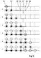
- Figure 4 illustrates the kinematic operation of the machine described by Figure 3.
- the upper diagram relates to the vocational step, and positions in time the 4 phases of it: feed (A), descent (D), return (R) and climb (M).
- the lower diagram relates to the manipulator 27, which presents the horizontal displacement phases: transfer (T) and return (R) between which the active "Pick” and "Place” operations take place. These operations having to intervene during the phases R of the vocational's step, it is clear that the cycle of the manipulator (C2) must be double that of the mit's step (C1).
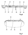
- FIG. 6 represents an exemplary embodiment of a double machine, which, as we have seen, is a borderline case where the tributary line is limited to the tributary track of the convergence station itself, without any other machine in upstream.
- the specific problem for this type of machine is to organize the recirculation of empty pallets between the upstream and downstream of the machine. This recirculation should preferably be done without encroaching on the space allocated to the working modules and their access, which practically prohibits the simple solution which would consist of a simple horizontal loop.
- the quantity of pallets to be put into service must be sufficient to occupy all the workstations on the tributary runway, plus a small additional quantity calculated so that there is never a wait for pallets at the end. entrance to the tributary track. As these pallets return empty, therefore in an unmarked state, there is no problem of concordance at the entry of the machine, therefore no need to provide a shift between the 2 tracks.
- a transfer manipulator 38 which ensures the transfer of the part or sub-assembly developed on the tributary track to the main track.
- FIG. 6 it is a mit step machine in phase, therefore equipped with a manipulator with double gripper, but one could imagine as well that it is a mit step machine in opposition, in which case we would have a simple gripper manipulator.
- FIG. 7 illustrates another variant of pallet recirculation presented according to an elevation view of the tributary track.
- the pallets 42 are hinged together so as to constitute an endless chain 43.
- the articulations of this chain must have the desired precision, but also a certain freedom to allow the normal play of grip and deposit by the step of the step of the step of
Landscapes
- Engineering & Computer Science (AREA)
- Mechanical Engineering (AREA)
- Automatic Assembly (AREA)
Claims (6)
- Fertigungseinrichtung mit einem Untergestell (50), zwei von dem Gestell getragenen Zustell- und Positioniersystemen (11, 11', 21, 21', 31, 31') zur Bildung von zwei parallelen Werkstück-Transportbahnen (1, 2) und einer Transfer-Handhabungseinrichtung (16, 27, 38), mit deren Hilfe ein Werkstück oder eine Unterbaugruppe von einer der beiden, eine Zulieferbahn bildenden Transportbahn entnommen und anschließend auf der anderen, eine Hauptbahn (1) bildenden Transportbahn abgelegt werden kann, wobei die verschiedenen Bewegungen miteinander synchronisiert sind,
dadurch gekennzeichnet, daß:- jedes Zustell- und Positioniersystem einen Pilgerschritt-Antriebsmechanismus zur Durchführung eines Rechteckzyklus' aufweist, der sich aus einer ersten, vertikalen Bewegung zur Aufnahme des Werkstücks, einer zweiten, horizontalen Bewegung zur Zustellung des Werkstücks, einer dritten, vertikalen Bewegung zur Positionierung des Werkstücks und einer vierten, horizontalen Rücklaufbewegung zusammensetzt,- sich die auf den Paletten (14) plazierten Werkstücke und Unterbaugruppen in der gleichen Richtung auf den beiden parallel angeordneten Transportbahnen (1, 2) bewegen, die innerhalb einer Übergabestation (3) zusammenlaufen, in der der Werkstücktransfer erfolgt,- zum An- und Abtransport dienende Förderanlagen vor bzw. hinter der Übergabestation (3) angeordnet sind und mit den beiden Pilgerschrittmechanismen zusammenwirken- und die Handhabungseinrichtung (17, 27, 38) quer zu den Transportbahnen (1, 2) angeordnet ist, wobei die genannte Einrichtung so ausgelegt ist, daß die Bewegungen der Pilgerschrittmechanismen und der Handhabungseinrichtung während des Betriebs miteinander synchronisiert sind. - Einrichtung nach Anspruch 1, dadurch gekennzeichnet, daß die beiden Pilgerschrittmechanismen (11, 11') gegenläufig arbeiten, so daß sich einer der Mechanismen in der ersten Aufnahmephase befindet, wenn sich der andere in der dritten Positionierphase befindet und umgekehrt, und daß die Transfer-Handhabungseinrichtung (16) mit einem Einzelgreifer ausgestattet ist, der im gleichen Takt arbeitet wie die Pilgerschrittmechanismen.
- Einrichtung nach Anspruch 1, dadurch gekennzeichnet, daß die beiden Pilgerschrittmechanismen (21, 21') im Gleichtakt arbeiten sowie die gleiche Bewegung beschreiben und daß die Transfer-Handhabungseinrichtung (27) mit einem Doppelgreifer ausgestattet ist und im Vergleich zu den Pilgerschrittmechanismen mit dem halben Takt arbeitet.
- Einrichtung nach einem der Ansprüche 1 bis 3, dadurch gekennzeichnet, daß die Rückführmittel die Rückführung der Paletten vom Ausgang zum Eingang der Übergabestation gewährleisten.
- Einrichtung nach Anspruch 4 mit einer Kombination aus Rutsche (36) und Förderer (37), dadurch gekennzeichnet, daß die Rückführung der Paletten unterhalb der Hauptbahn erfolgt (Fig. 6).
- Einrichtung nach Anspruch 4, dadurch gekennzeichnet, daß die Paletten (42) zu einer Endloskette (43) miteinander verbunden sind, die eine Aufnahme der Paletten durch den Pilgerschrittmechanismus (41') erlaubt und ihre Rückführung in der gleichen senkrechten Ebene unterhalb dieses Mechanismus' gewährleistet (Fig. 7).
Applications Claiming Priority (2)
| Application Number | Priority Date | Filing Date | Title |
|---|---|---|---|
| FR8912558A FR2652293B1 (fr) | 1989-09-22 | 1989-09-22 | Machine de production incorporant un dispositif rapide d'amenage et de positionnement a double pas de pelerin, et systeme de production mettant en óoeuvre ce type de machine. |
| FR8912558 | 1989-09-22 |
Publications (2)
| Publication Number | Publication Date |
|---|---|
| EP0419376A1 EP0419376A1 (de) | 1991-03-27 |
| EP0419376B1 true EP0419376B1 (de) | 1994-03-02 |
Family
ID=9385810
Family Applications (1)
| Application Number | Title | Priority Date | Filing Date |
|---|---|---|---|
| EP90420402A Expired - Lifetime EP0419376B1 (de) | 1989-09-22 | 1990-09-12 | Fertigungseinrichtung mit einer Vorrichtung zum schnellen Zuführen und Positionieren im doppelten Pilgerschritt und Fertigungssystem zum Verwenden dieser Einrichtung |
Country Status (4)
| Country | Link |
|---|---|
| US (1) | US5062525A (de) |
| EP (1) | EP0419376B1 (de) |
| DE (1) | DE69006993T2 (de) |
| FR (1) | FR2652293B1 (de) |
Families Citing this family (4)
| Publication number | Priority date | Publication date | Assignee | Title |
|---|---|---|---|---|
| DE19514206A1 (de) * | 1995-04-15 | 1996-10-17 | Opel Adam Ag | Bearbeitungs- und/oder Montageanlage |
| DE19749450C2 (de) * | 1997-11-10 | 1999-09-02 | Multiline International Europa | Vorrichtung zum Transport von Werkstückhaltern im Kreislauf |
| US6314337B1 (en) | 1998-08-27 | 2001-11-06 | Dell Usa, L.P. | Automated consolidation station |
| US10427254B2 (en) * | 2014-04-30 | 2019-10-01 | The Boeing Company | Flexible manufacturing for aircraft structures |
Family Cites Families (18)
| Publication number | Priority date | Publication date | Assignee | Title |
|---|---|---|---|---|
| US2943726A (en) * | 1957-11-12 | 1960-07-05 | Simpson Herbert Corp | Drive for mold conveyor systems |
| US2969750A (en) * | 1957-12-06 | 1961-01-31 | Udylite Corp | Rack loading and unloading mechanism |
| FR1604142A (de) * | 1967-12-22 | 1971-07-12 | ||
| US3571892A (en) * | 1969-01-08 | 1971-03-23 | Majestic Penn State Inc | Conveyor system |
| US3785031A (en) * | 1972-07-19 | 1974-01-15 | Standard Tool & Mfg Co | Nonsynchronous conveyor system |
| US3850213A (en) * | 1973-09-26 | 1974-11-26 | C Keaton | Continuous press |
| US4029215A (en) * | 1975-07-01 | 1977-06-14 | Midcon Pipeline Equipment Co. | Pipe handling apparatus for pipe laying barges |
| IT1133674B (it) * | 1980-10-02 | 1986-07-09 | Ind Bagnolo S I B Srl Soc | Trasportatore a nastro in tessuto metallico ad avanzamento intermittente,particolarmente per il trasporto di materiali in forni industriali |
| JPS5771741A (en) * | 1980-10-15 | 1982-05-04 | Mazda Motor Corp | Circulating system for truck for assembling article |
| JPS57145718A (en) * | 1981-03-02 | 1982-09-08 | C Uyemura & Co Ltd | Direction changing device in conveyor system |
| SU1089016A1 (ru) * | 1982-09-17 | 1984-04-30 | Ленинградский Филиал Всесоюзного Института По Проектированию Организации Энергетического Строительства "Оргэнергострой" | Устройство дл перегрузки изделий с одного конвейера на другой |
| CH657301A5 (de) * | 1982-09-23 | 1986-08-29 | Lothar Kaiser | Montageverfahren mit roboter. |
| CA1251413A (en) * | 1983-09-08 | 1989-03-21 | Shinichi Kawai | Conveyor system for use in automobile assembly line |
| JPS6216921A (ja) * | 1985-07-12 | 1987-01-26 | Matsushita Electric Ind Co Ltd | 間欠移載装置 |
| JPS6357130A (ja) * | 1986-08-27 | 1988-03-11 | Honda Motor Co Ltd | 自動組付装置 |
| JPS6362624A (ja) * | 1986-09-03 | 1988-03-18 | Honda Motor Co Ltd | 車両用エンジンにおけるクランクケ−ス組付方法 |
| DE3872429T2 (de) * | 1987-03-06 | 1993-02-18 | Merlin Gerin | Fertigungssystem mit einer schnellen vorrichtung zum zufuehren und positionieren mit rechteckiger bewegung. |
| JPH07106512B2 (ja) * | 1987-04-30 | 1995-11-15 | 本田技研工業株式会社 | ベルト及びプ−リの同時組付け方法及び装置 |
-
1989
- 1989-09-22 FR FR8912558A patent/FR2652293B1/fr not_active Expired - Fee Related
-
1990
- 1990-09-12 DE DE69006993T patent/DE69006993T2/de not_active Expired - Fee Related
- 1990-09-12 EP EP90420402A patent/EP0419376B1/de not_active Expired - Lifetime
- 1990-09-24 US US07/587,355 patent/US5062525A/en not_active Expired - Fee Related
Also Published As
| Publication number | Publication date |
|---|---|
| DE69006993D1 (de) | 1994-04-07 |
| FR2652293B1 (fr) | 1995-03-17 |
| FR2652293A1 (fr) | 1991-03-29 |
| DE69006993T2 (de) | 1994-08-04 |
| US5062525A (en) | 1991-11-05 |
| EP0419376A1 (de) | 1991-03-27 |
Similar Documents
| Publication | Publication Date | Title |
|---|---|---|
| FR3072954A1 (fr) | Appareil de transfert | |
| FR2813295A1 (fr) | Procede et dispositif de mise en file d'objets | |
| WO2019129968A1 (fr) | Déplacement de produits sur une zone de transit | |
| FR2993871A1 (fr) | Dispositif et procede de convoyage multivoies | |
| EP0481901A1 (de) | Verfahren und Anordnungen zur automatischen Verbindung von Abschnittsenden von Leiterdrähten oder optischen Fasern an angepasste Buchsen von Komponenten | |
| FR2685685A1 (fr) | Dispositif pour empiler des liasses de feuilles. | |
| FR3083532A1 (fr) | Dispositif de transfert perfectionne | |
| EP2196395A1 (de) | Vorrichtung und Verfahren zur Verpackung von Spritzen in Nestern | |
| EP0286546B1 (de) | Fertigungssystem mit einer schnellen Vorrichtung zum Zuführen und Positionieren mit rechteckiger Bewegung | |
| EP0419376B1 (de) | Fertigungseinrichtung mit einer Vorrichtung zum schnellen Zuführen und Positionieren im doppelten Pilgerschritt und Fertigungssystem zum Verwenden dieser Einrichtung | |
| FR2639907A1 (fr) | Procede d'alimentation automatique d'une ligne d'embouteillage. ensemble et dispositif pour sa mise en oeuvr | |
| WO2020064860A1 (fr) | Dispositif et procede de transfert de produits | |
| EP0617691B1 (de) | Verfahren und vorrichtung zum bewegen von gegenständen um eine bahn und verwendung der vorrichtung | |
| EP3305692B1 (de) | Transfer von gegenständen | |
| FR2631604A1 (fr) | Procede et installation de traitement d'objets, notamment pour chaines d'emballage automatique | |
| EP0148091B1 (de) | Vorrichtung zum Transferieren von Kernbrennstoffhüllen in einer festen Tablettenfüllungsstation | |
| FR2587015A1 (fr) | Transporteur pour machine a assembler des feuilles de papier et machines en faisant application | |
| FR2538355A1 (fr) | Procede et installation de manutention de tuyaux en fonte a emboitement en vue de transformer des groupes de tuyaux en nombre pair en groupes de tuyaux en nombre impair | |
| US4059261A (en) | Machine and method for successively feeding stacked blanks | |
| US3527366A (en) | Cigarette parcelling machine | |
| FR2612487A1 (fr) | Procede d'encaissage en continu et suivant des couches superposees, d'objets tels que par exemple des recipients, et machine comportant application de ce procede | |
| FR2606381A1 (fr) | Procede et dispositif de chargement de produits bruts ou conditionnes sur un support de stockage | |
| EP0542642B1 (de) | Vorrichtung zum schnellen Zuführen und Positionieren mit horizontalen abgestuftem Hub | |
| EP0475827A1 (de) | Übergabevorrichtung für Gegenstände verschiedener Art zur Konditionierung derselben | |
| US3836016A (en) | Apparatus for the transport and intermediate storage of panel supports |
Legal Events
| Date | Code | Title | Description |
|---|---|---|---|
| PUAI | Public reference made under article 153(3) epc to a published international application that has entered the european phase |
Free format text: ORIGINAL CODE: 0009012 |
|
| AK | Designated contracting states |
Kind code of ref document: A1 Designated state(s): BE CH DE GB IT LI SE |
|
| 17P | Request for examination filed |
Effective date: 19910920 |
|
| 17Q | First examination report despatched |
Effective date: 19921116 |
|
| GRAA | (expected) grant |
Free format text: ORIGINAL CODE: 0009210 |
|
| AK | Designated contracting states |
Kind code of ref document: B1 Designated state(s): BE CH DE GB IT LI SE |
|
| PG25 | Lapsed in a contracting state [announced via postgrant information from national office to epo] |
Ref country code: SE Free format text: THE PATENT HAS BEEN ANNULLED BY A DECISION OF A NATIONAL AUTHORITY Effective date: 19940302 Ref country code: GB Effective date: 19940302 |
|
| REF | Corresponds to: |
Ref document number: 69006993 Country of ref document: DE Date of ref document: 19940407 |
|
| ITF | It: translation for a ep patent filed | ||
| GBV | Gb: ep patent (uk) treated as always having been void in accordance with gb section 77(7)/1977 [no translation filed] |
Effective date: 19940302 |
|
| PG25 | Lapsed in a contracting state [announced via postgrant information from national office to epo] |
Ref country code: BE Effective date: 19940930 |
|
| PLBE | No opposition filed within time limit |
Free format text: ORIGINAL CODE: 0009261 |
|
| STAA | Information on the status of an ep patent application or granted ep patent |
Free format text: STATUS: NO OPPOSITION FILED WITHIN TIME LIMIT |
|
| 26N | No opposition filed | ||
| BERE | Be: lapsed |
Owner name: MERLIN GERIN Effective date: 19940930 |
|
| PGFP | Annual fee paid to national office [announced via postgrant information from national office to epo] |
Ref country code: DE Payment date: 20010906 Year of fee payment: 12 |
|
| PGFP | Annual fee paid to national office [announced via postgrant information from national office to epo] |
Ref country code: CH Payment date: 20010914 Year of fee payment: 12 |
|
| PG25 | Lapsed in a contracting state [announced via postgrant information from national office to epo] |
Ref country code: LI Free format text: LAPSE BECAUSE OF NON-PAYMENT OF DUE FEES Effective date: 20020930 Ref country code: CH Free format text: LAPSE BECAUSE OF NON-PAYMENT OF DUE FEES Effective date: 20020930 |
|
| PG25 | Lapsed in a contracting state [announced via postgrant information from national office to epo] |
Ref country code: DE Free format text: LAPSE BECAUSE OF NON-PAYMENT OF DUE FEES Effective date: 20030401 |
|
| REG | Reference to a national code |
Ref country code: CH Ref legal event code: PL |
|
| PG25 | Lapsed in a contracting state [announced via postgrant information from national office to epo] |
Ref country code: IT Free format text: LAPSE BECAUSE OF NON-PAYMENT OF DUE FEES;WARNING: LAPSES OF ITALIAN PATENTS WITH EFFECTIVE DATE BEFORE 2007 MAY HAVE OCCURRED AT ANY TIME BEFORE 2007. THE CORRECT EFFECTIVE DATE MAY BE DIFFERENT FROM THE ONE RECORDED. Effective date: 20050912 |