EP0148092A2 - Bearbeitungsmaschine und Beschickungsvorrichtung für die Herstellung von Gegenständen - Google Patents
Bearbeitungsmaschine und Beschickungsvorrichtung für die Herstellung von Gegenständen Download PDFInfo
- Publication number
- EP0148092A2 EP0148092A2 EP84402752A EP84402752A EP0148092A2 EP 0148092 A2 EP0148092 A2 EP 0148092A2 EP 84402752 A EP84402752 A EP 84402752A EP 84402752 A EP84402752 A EP 84402752A EP 0148092 A2 EP0148092 A2 EP 0148092A2
- Authority
- EP
- European Patent Office
- Prior art keywords
- station
- transporter
- sheaths
- objects
- conveyor
- Prior art date
- Legal status (The legal status is an assumption and is not a legal conclusion. Google has not performed a legal analysis and makes no representation as to the accuracy of the status listed.)
- Granted
Links
- 238000009434 installation Methods 0.000 title claims abstract description 28
- 238000004519 manufacturing process Methods 0.000 title claims description 24
- 238000003754 machining Methods 0.000 title 1
- 238000011084 recovery Methods 0.000 claims abstract description 14
- 238000012432 intermediate storage Methods 0.000 claims abstract description 11
- 238000011144 upstream manufacturing Methods 0.000 claims abstract description 11
- 238000000151 deposition Methods 0.000 claims description 5
- 239000003758 nuclear fuel Substances 0.000 claims description 4
- 238000005096 rolling process Methods 0.000 claims description 2
- 238000003860 storage Methods 0.000 description 17
- 238000003032 molecular docking Methods 0.000 description 5
- 239000000446 fuel Substances 0.000 description 4
- 230000009467 reduction Effects 0.000 description 4
- 230000008439 repair process Effects 0.000 description 4
- 238000003466 welding Methods 0.000 description 4
- 238000013016 damping Methods 0.000 description 3
- 239000008188 pellet Substances 0.000 description 3
- 229920000297 Rayon Polymers 0.000 description 2
- 239000000969 carrier Substances 0.000 description 2
- 230000002950 deficient Effects 0.000 description 2
- 238000010586 diagram Methods 0.000 description 2
- 238000003780 insertion Methods 0.000 description 2
- 230000037431 insertion Effects 0.000 description 2
- 238000007689 inspection Methods 0.000 description 2
- 230000007246 mechanism Effects 0.000 description 2
- 230000036515 potency Effects 0.000 description 2
- 239000002964 rayon Substances 0.000 description 2
- 230000000284 resting effect Effects 0.000 description 2
- 238000007789 sealing Methods 0.000 description 2
- 241000282898 Sus scrofa Species 0.000 description 1
- WZECUPJJEIXUKY-UHFFFAOYSA-N [O-2].[O-2].[O-2].[U+6] Chemical compound [O-2].[O-2].[O-2].[U+6] WZECUPJJEIXUKY-UHFFFAOYSA-N 0.000 description 1
- 239000006096 absorbing agent Substances 0.000 description 1
- 230000004913 activation Effects 0.000 description 1
- 238000000429 assembly Methods 0.000 description 1
- 230000000712 assembly Effects 0.000 description 1
- 230000003416 augmentation Effects 0.000 description 1
- 230000008859 change Effects 0.000 description 1
- 230000009194 climbing Effects 0.000 description 1
- 239000011248 coating agent Substances 0.000 description 1
- 238000000576 coating method Methods 0.000 description 1
- 230000007547 defect Effects 0.000 description 1
- 230000001419 dependent effect Effects 0.000 description 1
- 238000009826 distribution Methods 0.000 description 1
- 238000000605 extraction Methods 0.000 description 1
- 238000009432 framing Methods 0.000 description 1
- 239000000463 material Substances 0.000 description 1
- 229910052751 metal Inorganic materials 0.000 description 1
- 239000002184 metal Substances 0.000 description 1
- 235000010603 pastilles Nutrition 0.000 description 1
- 230000035939 shock Effects 0.000 description 1
- 229910000439 uranium oxide Inorganic materials 0.000 description 1
- 230000000007 visual effect Effects 0.000 description 1
- 238000011179 visual inspection Methods 0.000 description 1
- XLYOFNOQVPJJNP-UHFFFAOYSA-N water Substances O XLYOFNOQVPJJNP-UHFFFAOYSA-N 0.000 description 1
Images


Classifications
-
- B—PERFORMING OPERATIONS; TRANSPORTING
- B65—CONVEYING; PACKING; STORING; HANDLING THIN OR FILAMENTARY MATERIAL
- B65G—TRANSPORT OR STORAGE DEVICES, e.g. CONVEYORS FOR LOADING OR TIPPING, SHOP CONVEYOR SYSTEMS OR PNEUMATIC TUBE CONVEYORS
- B65G37/00—Combinations of mechanical conveyors of the same kind, or of different kinds, of interest apart from their application in particular machines or use in particular manufacturing processes
- B65G37/02—Flow-sheets for conveyor combinations in warehouses, magazines or workshops
-
- B—PERFORMING OPERATIONS; TRANSPORTING
- B23—MACHINE TOOLS; METAL-WORKING NOT OTHERWISE PROVIDED FOR
- B23Q—DETAILS, COMPONENTS, OR ACCESSORIES FOR MACHINE TOOLS, e.g. ARRANGEMENTS FOR COPYING OR CONTROLLING; MACHINE TOOLS IN GENERAL CHARACTERISED BY THE CONSTRUCTION OF PARTICULAR DETAILS OR COMPONENTS; COMBINATIONS OR ASSOCIATIONS OF METAL-WORKING MACHINES, NOT DIRECTED TO A PARTICULAR RESULT
- B23Q7/00—Arrangements for handling work specially combined with or arranged in, or specially adapted for use in connection with, machine tools, e.g. for conveying, loading, positioning, discharging, sorting
- B23Q7/14—Arrangements for handling work specially combined with or arranged in, or specially adapted for use in connection with, machine tools, e.g. for conveying, loading, positioning, discharging, sorting co-ordinated in production lines
-
- G—PHYSICS
- G21—NUCLEAR PHYSICS; NUCLEAR ENGINEERING
- G21C—NUCLEAR REACTORS
- G21C21/00—Apparatus or processes specially adapted to the manufacture of reactors or parts thereof
-
- Y—GENERAL TAGGING OF NEW TECHNOLOGICAL DEVELOPMENTS; GENERAL TAGGING OF CROSS-SECTIONAL TECHNOLOGIES SPANNING OVER SEVERAL SECTIONS OF THE IPC; TECHNICAL SUBJECTS COVERED BY FORMER USPC CROSS-REFERENCE ART COLLECTIONS [XRACs] AND DIGESTS
- Y02—TECHNOLOGIES OR APPLICATIONS FOR MITIGATION OR ADAPTATION AGAINST CLIMATE CHANGE
- Y02E—REDUCTION OF GREENHOUSE GAS [GHG] EMISSIONS, RELATED TO ENERGY GENERATION, TRANSMISSION OR DISTRIBUTION
- Y02E30/00—Energy generation of nuclear origin
- Y02E30/30—Nuclear fission reactors
-
- Y—GENERAL TAGGING OF NEW TECHNOLOGICAL DEVELOPMENTS; GENERAL TAGGING OF CROSS-SECTIONAL TECHNOLOGIES SPANNING OVER SEVERAL SECTIONS OF THE IPC; TECHNICAL SUBJECTS COVERED BY FORMER USPC CROSS-REFERENCE ART COLLECTIONS [XRACs] AND DIGESTS
- Y02—TECHNOLOGIES OR APPLICATIONS FOR MITIGATION OR ADAPTATION AGAINST CLIMATE CHANGE
- Y02P—CLIMATE CHANGE MITIGATION TECHNOLOGIES IN THE PRODUCTION OR PROCESSING OF GOODS
- Y02P90/00—Enabling technologies with a potential contribution to greenhouse gas [GHG] emissions mitigation
- Y02P90/02—Total factory control, e.g. smart factories, flexible manufacturing systems [FMS] or integrated manufacturing systems [IMS]
Definitions
- the subject of the invention is a manufacturing installation of the type comprising several fixed work stations which must successively pass through all identical objects during their manufacture. It finds a particularly important application in the manufacture of nuclear fuel rods constituted by an elongated sealed sheath containing a stack of pellets of combustible material and closed by plugs. However, it can also be used whenever the object to be treated has a general external shape which remains invariable during manufacture and, above all, when it has an approximately elongated cylindrical shape.
- An object must frequently, during its manufacture, be treated at several successive stations. It is common practice to provide, between these stations, a conveyor, possibly including storage means forming a buffer and compensating for manufacturing jolts at each station. Such an installation has the disadvantage of being relatively fixed and of allowing only with difficulty transfers of some of the objects to particular locations, for example to a repair shop or to a scrap, following a defect which has appeared. at a checkpoint.
- the invention aims to provide a manufacturing installation with several workstations and an automated handling device which better meets those previously known than the requirements of the practice, in particular in that it allows sufficient intermediate storage to ensure the regularity of the operation. without requiring a complex handling device and while ensuring great independence of operation between the different workstations and the handling means.
- the invention notably proposes a manufacturing installation of the type defined above, in which the work stations are arranged along at least one handling bay, characterized in that the handling device comprises, on the one hand, an air conveyor mobile along the bay and provided with means making it possible to grasp, to transport and deposit a batch of a determined number of objects, on the other hand, in front of each work station, an intermediate storage and recovery device having an upstream station for deposit by the transporter, a downstream station recovery by the transporter and a conveyor capable of grasping the batch of objects in a block at the upstream station, presenting the objects one by one at the work station and placing them in a block at the downstream station.
- the handling device comprises, on the one hand, an air conveyor mobile along the bay and provided with means making it possible to grasp, to transport and deposit a batch of a determined number of objects, on the other hand, in front of each work station, an intermediate storage and recovery device having an upstream station for deposit by the transporter, a downstream station recovery by the transporter and a conveyor capable of grasping the batch
- each intermediate storage device advantageously comprises a conveyor having several parallel endless belts provided with notches for receiving the pencils at a pitch greater than the diameter of the latter and the upstream and downstream stations have parallel supports provided with notches at the same pitch as that of the belts, which can take a high position above the conveyor to support the pencils and a low position in which the rods rest on the conveyor.
- the air carrier can then comprise an overhead crane along the span, provided with a lifter movable vertically and comprising keys insertable between pencils and making it possible to grasp the latter. Due to the reduced diameter of the pencils, the latter can easily be grouped in large numbers (by twenty-four for example), in the form of a sheet having a reduced transverse dimension.
- the workstations can be distributed along two parallel spans each provided with a conveyor, the passage of the objects from one span to the other being carried out using 'a ferry.
- the area between the two spans can be occupied by stations working on one side or on both sides. This reduces the longitudinal size and can also reserve additional areas, including storage areas.
- An additional ferry located at the end of the spans can be provided to serve these additional areas.
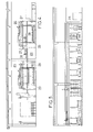
- the installation shown in Figure 2 includes two handling spans 16 and 18 each served by a transporter 20.
- Two ferries 22 and 24 allow a batch of pencils to be moved at the same time from one bay to another, between two access locations -sible by overhead traveling cranes constituting air carriers. These ferries also serve, one a final storage area 23, the other, a buffer storage area 25 each placed on one side of the set of spans.
- These zones occupy only a fraction of the length of the handling spans.
- the rest of the length of the lateral zones can constitute lateral manufacturing spans, occupied by work stations in addition to those occupying a central manufacturing span 26.
- the handling spans 16 and 18 are framed by beams 27 connecting gantries and on which flow rails rest. They are equipped with sets of fixed guides 29 resting on the ground, each set being at the level of a fixed manufacturing station, the latter term designating a location where an intervention is carried out which may be of assembly, manufacture or control. Only one of these sets 29 is schematically mounted in FIG. 2. These sets of guides 29 have the role of ensuring the required precision of removal and recovery of a batch of sheaths or pencils on the associated intermediate storage device 28 at each work station.
- the devices make it possible to carry out the various functions which may have any suitable constitution.
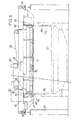
- the two conveyors 20 are practically identical, so that only one will be described. They can be viewed as constituted by an overhead crane 30 with an apron and a lifting beam 32.
- the overhead crane is equipped with two rolling bogies 34 resting on two fixed rails located above the beams 27.
- a geared motor 35 mounted on the overhead crane simultaneously controls, via two half-shafts, the driving wheels of the bogies 34.
- the lifter 32 is suspended from the bridge 30 by two cables 36 provided with shock absorbers and a force limiter 38.
- a set of pulleys mounted on the deck of the bridge leads each cable to a reel located at the end of a geared motor 40 vertical movement of the lifter 32.
- the ends of the lifter carry two vertical lateral guides 42 in the shape of a U which engage on rollers carried by brackets 44, 46 fixed under the deck of the bridge.
- the roller train carried by the bracket 44 is not directly attached to this bracket. It is mounted on a chassis that can be moved horizontally, in a vertical plane perpendicular to the lifter, relative to the bracket 44. This chassis 47 is guided and an independent motor 48 makes it possible to move it so as to make up for errors in the location of stop of the corresponding end of the lifter 32.
- the mass and the size of the conveyor do not allow absolute rigidity and perfect guidance. If, as will be seen below, the stopping of the overhead crane is controlled by a photoelectric cell mounted on the bracket 46, it is indeed possible to stop the end of the bridge carrying the bracket 46 at a desired location but the other end may then be shifted. This makes it necessary to readjust the spreader 32 by moving the chassis.
- the correct location can be defined by a system of two photoelectric cells carried by the chassis 47 and cooperating with two fixed tell-tales 49.
- the underside of the lifter 32 carries a device for taking up sheaths or pencils.
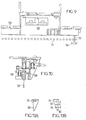
- This device comprises a set of parallel sleepers 50 each equipped with a series of fingers 52 rotating around a vertical axis each carrying a key with two opposite hooks 54 (Figure 9).
- a mechanism for entrainment in rotation of the fingers 52 comprises movable crosspieces 56 ( Figure 10) which drive an arm 58 pivoting by a linkage 60 ( Figure 11) actuating turntables 62 connected to the movable crosspieces.
- One of the plates 62 is connected to a motor 64 which causes the plates to rotate 90 ° each time to cause the simultaneous rotation of all the keys, also 90 °.
- Limiting the change of orientation to 90 ° at each actuation can be carried out using contactors 66 cooperating with a finger driven by the motor 64 ( Figure 11).
- the actuation of the motor 64 makes it possible to rotate the fingers 52 by 90 ° and to put the hooks in the gripping position once the keys 54 have been inserted in a sheet of sheaths or pencils carried by a rack in order allow the lifter to lift the tablecloth.
- Another activation makes it possible to abandon a sheet of pencils after laying them and then to release the lifter.
- the transporter is also provided with a docking device, which cooperates with the fixed guides and will be described after them.
- Each of the fixed removal and recovery guides can be viewed as comprising a rack table 67 constituting an interface with the corresponding storage device 28 and two uprights, 68, 69, framing the handling bay.
- the uprights each carry a vertical row of rollers 70 of which only a few are shown. These rollers provide the relay for guiding the lifter 32 in its downward movements by docking of the two slides 42 on the rollers 76.
- the upright 63 carries a fixed indicator at the head which cooperates with a cell carried by the bridge to control the stop it.
- the upright 74 carries, him, the two fixed witnesses 49 which, by the intermediary of the two cells carried by the movable frame 47 of the stem 44 ensure the re-alignment of the lifter until its slide 42 is placed vertically the row of pebbles 76 of the upright 74.
- Table 67 is equipped with a deposit rack having locations for receiving a sheet of sheaths or pencils in step with the series of keys of the lifter.
- the storage device associated with this table and a second table offset in the direction of the span ensures the presence tation of each sheath successively at the work station or its evacuation.
- FIG. 14 very schematically shows a possible constitution of a storage device making it possible to completely decouple the handling along the span using the conveyor 20 and the presentation of each ga.ir r e or pencil in turn at the workstation.
- each device intended to intervene on the sheath or the pencil, indicated in 78 is associated with a work station placed opposite.
- This work station is framed, in the longitudinal direction, by an upstream depositing station by the transporter 20 and a downstream recovery station by the transporter.
- Each of these stations has a rack, 67a at the first station, 67b at the second.
- This rack is framed transversely by two guides, 29a in the first case, 29b in the second.
- Each rack is movable vertically between a high position, in which it is shown in Figure 14, and a low position (in dashed lines in Figure).
- a high position in which it is shown in Figure 14, and a low position (in dashed lines in Figure).
- the rack When the rack is in the high position, it can receive sleeves or pencils 13 by lowering the lifter 32 carrying a sheet of sleeves or pencils, rotation of the keys 54 and raising of the lifter.
- the rack When the rack is in the low position, it abandons the sheaths or pencils which it places on a conveyor 80 provided with pins distributed at the same pace as the notches of the rack 67a.
- the rack and the conveyor are obviously formed in the form of longitudinal strips of width and spacing such that they can be nested one inside the other.
- the rack and its up and down mechanism can in particular have the constitution described in patent application FR No. 83 21125.
- the conveyor it is possible for the conveyor to receive a sheet of sheaths or pencils, then to move them until it has cleared them from the rack.
- the rack can then be raised. It is again ready to receive a sheet of sleeves or pencils. It is the same for the rack 67b, which ensures complete decoupling between the storage function and the function of presentation at the workstation of successive sleeves or pencils, which is carried out in advance step by step of the conveyor 80 .
- the slides are provided with a flexible chamfered coating on the inlet and outlet side.
- the first rollers of the gallows and the uprights can be given a diameter slightly smaller than that of the others.
- the speed reduction function must take place when lowering, when the lifter is approaching its low stop position, and when climbing, when the spreader arrives in the high position.
- the speed reduction can be ensured by a device mounted on each upright 68, 69 which comprises two cam switches, the first reducing the descent speed, the second causing the lifter to stop.
- the deceleration, as well as the increase in speed after a determined route are controlled by finger contactors mounted stepped on the bracket 46 of the bridge. Three of the contactors 71, 72 and 74 are placed on one side of the bracket 46 ( Figure 13A).
- the contactor 71 is mounted in a circuit to reduce the ascent speed, the second, 72, to increase the descent speed, the third, 74, to cause the stop in the high position.
- a fourth cam switch 76 is mounted on the other side of the bracket ( Figure 13B). It is intended to authorize the recentering of the bridge using the mobile chassis only when it is closed, while the lifter is in the high position.
- a batch of sheaths in the form of a sheet is firstly gripped by the conveyor of span 16.
- the conveyor brings this tablecloth , which can for example include twenty-four sheaths, at the marking station M.
- the transporter takes up the sheet of marked sheaths and deposits them on the rack table of the station for mounting the plugs EM1.
- the sheet is taken up by the transporter and it travels through the following stations.
- certain operations require a significant storage period: this is the case, for example, for radiographic control at the RX1 station.
- a dynamic intermediate storage station S1 is provided with two depositing stations and two recovery stations served by the transporter.
- Dynamic storage with seven horizontal beds of deposit tables, each erasable by translation to allow access to all the stored ducts, will generally be satisfactory.
- the TR1 sorting table that follows storage allows manual extraction of defective sheaths and replacement. This sorting table can include three successive stations, the first being reserved only for removal, the second for recovery, the third for pickup and removal to a repair shop.
- the sheath layers are taken up by the transporter and brought to the next station, that is to say to the filling station R1.
- This post and the following three require an intervention on the end of the sheath or pencil opposite to that treated so far. Thanks to the relative arrangement adopted for the handling spans and the manufacturing spans, this intervention on one end, then on the other, is possible without turning the sheaths.
- the pencils can be placed on a storage station before being brought to an additional workshop where the complete assemblies are made.
Landscapes
- Engineering & Computer Science (AREA)
- Physics & Mathematics (AREA)
- Mechanical Engineering (AREA)
- Manufacturing & Machinery (AREA)
- Plasma & Fusion (AREA)
- General Engineering & Computer Science (AREA)
- High Energy & Nuclear Physics (AREA)
- Specific Conveyance Elements (AREA)
- Automatic Assembly (AREA)
- Monitoring And Testing Of Nuclear Reactors (AREA)
- Branching, Merging, And Special Transfer Between Conveyors (AREA)
- Intermediate Stations On Conveyors (AREA)
- Multi-Process Working Machines And Systems (AREA)
- General Factory Administration (AREA)
- Butt Welding And Welding Of Specific Article (AREA)
- Warehouses Or Storage Devices (AREA)
Applications Claiming Priority (2)
| Application Number | Priority Date | Filing Date | Title |
|---|---|---|---|
| FR8321126 | 1983-12-30 | ||
| FR8321126A FR2557547B1 (fr) | 1983-12-30 | 1983-12-30 | Installation de fabrication a plusieurs postes fixes de travail et a dispositif de manutention |
Publications (3)
| Publication Number | Publication Date |
|---|---|
| EP0148092A2 true EP0148092A2 (de) | 1985-07-10 |
| EP0148092A3 EP0148092A3 (en) | 1985-08-14 |
| EP0148092B1 EP0148092B1 (de) | 1987-09-09 |
Family
ID=9295769
Family Applications (1)
| Application Number | Title | Priority Date | Filing Date |
|---|---|---|---|
| EP84402752A Expired EP0148092B1 (de) | 1983-12-30 | 1984-12-28 | Bearbeitungsmaschine und Beschickungsvorrichtung für die Herstellung von Gegenständen |
Country Status (8)
| Country | Link |
|---|---|
| US (1) | US4700824A (de) |
| EP (1) | EP0148092B1 (de) |
| JP (1) | JPS60180735A (de) |
| KR (1) | KR920008013B1 (de) |
| DE (1) | DE3465958D1 (de) |
| ES (1) | ES8701109A1 (de) |
| FR (1) | FR2557547B1 (de) |
| ZA (1) | ZA8410132B (de) |
Cited By (1)
| Publication number | Priority date | Publication date | Assignee | Title |
|---|---|---|---|---|
| CN111791065A (zh) * | 2020-06-13 | 2020-10-20 | 宁波润轴汽配有限公司 | 一种轴加工流水线 |
Families Citing this family (8)
| Publication number | Priority date | Publication date | Assignee | Title |
|---|---|---|---|---|
| JPH06104554B2 (ja) * | 1986-06-13 | 1994-12-21 | 村田機械株式会社 | 天井自走車 |
| DE3740597A1 (de) * | 1987-11-30 | 1989-06-08 | Grieshaber Masch | Flexible mehrstationige maschine zur bearbeitung von rotationssymmetrischen oberflaechen |
| US4980119A (en) * | 1989-04-04 | 1990-12-25 | General Electric Company | Multizone automated nuclear fuel rod loading system |
| DE4007801A1 (de) * | 1990-03-12 | 1991-09-19 | Handtmann A Punkt Automation | Einrichtung zum befuellen eines transportbehaelters |
| JPH0650201A (ja) * | 1992-04-30 | 1994-02-22 | Nippondenso Co Ltd | スロットル弁の駆動装置 |
| US6854582B1 (en) * | 2003-09-20 | 2005-02-15 | Formax, Inc. | Stack stop for conveyor system |
| CN105632987B (zh) * | 2016-01-05 | 2019-03-26 | 新奥光伏能源有限公司 | 一种周转设备、周转方法以及太阳能电池生产线 |
| CN108838687A (zh) * | 2018-08-10 | 2018-11-20 | 浙江泰鸿万立科技股份有限公司 | 一种车身件自动生产线系统 |
Family Cites Families (8)
| Publication number | Priority date | Publication date | Assignee | Title |
|---|---|---|---|---|
| FR1089081A (fr) * | 1952-12-13 | 1955-03-14 | Mannesmann Ag | Presse à usiner les extrémités de tubes |
| GB764985A (en) * | 1954-06-02 | 1957-01-02 | Llewellyn Alwin Hautau | A mechanical loader and unloader for production machines |
| US3149736A (en) * | 1957-08-21 | 1964-09-22 | Bendix Corp | Tote box handling mechanism |
| US2975882A (en) * | 1957-11-05 | 1961-03-21 | Harold G Abbey | Mechanisms for individual carrier selection of processing cycle in conveyor systems |
| US3024058A (en) * | 1958-06-09 | 1962-03-06 | Leo D Reel | Apparatus for engaging and moving elongated tubular objects such as pipe and the like of varying lengths and diameters |
| FR1209491A (fr) * | 1958-08-08 | 1960-03-02 | Renault | Dispositif de prélèvement ou de déchargement de pièces sur une chaîne de manutention à mouvement continu |
| US3658197A (en) * | 1970-06-01 | 1972-04-25 | Lockheed Aircraft Corp | Programmable apparatus for conveying articles through successive process steps |
| CH597059A5 (de) * | 1976-12-15 | 1978-03-31 | Micafil Ag |
-
1983
- 1983-12-30 FR FR8321126A patent/FR2557547B1/fr not_active Expired
-
1984
- 1984-12-28 EP EP84402752A patent/EP0148092B1/de not_active Expired
- 1984-12-28 US US06/687,344 patent/US4700824A/en not_active Expired - Lifetime
- 1984-12-28 ES ES539532A patent/ES8701109A1/es not_active Expired
- 1984-12-28 ZA ZA8410132A patent/ZA8410132B/xx unknown
- 1984-12-28 DE DE8484402752T patent/DE3465958D1/de not_active Expired
- 1984-12-28 JP JP59281844A patent/JPS60180735A/ja active Pending
- 1984-12-29 KR KR1019840008550A patent/KR920008013B1/ko not_active Expired
Cited By (1)
| Publication number | Priority date | Publication date | Assignee | Title |
|---|---|---|---|---|
| CN111791065A (zh) * | 2020-06-13 | 2020-10-20 | 宁波润轴汽配有限公司 | 一种轴加工流水线 |
Also Published As
| Publication number | Publication date |
|---|---|
| KR850004436A (ko) | 1985-07-15 |
| JPS60180735A (ja) | 1985-09-14 |
| EP0148092A3 (en) | 1985-08-14 |
| US4700824A (en) | 1987-10-20 |
| ES8701109A1 (es) | 1986-12-01 |
| ZA8410132B (en) | 1986-02-26 |
| EP0148092B1 (de) | 1987-09-09 |
| KR920008013B1 (ko) | 1992-09-21 |
| FR2557547A1 (fr) | 1985-07-05 |
| ES539532A0 (es) | 1986-12-01 |
| DE3465958D1 (en) | 1987-10-15 |
| FR2557547B1 (fr) | 1986-05-30 |
Similar Documents
| Publication | Publication Date | Title |
|---|---|---|
| WO2019129968A1 (fr) | Déplacement de produits sur une zone de transit | |
| BE897551A (fr) | Systeme automatique d'assemblage et de soudage d'ensembles faconnes en toles metalliques. | |
| EP0148092B1 (de) | Bearbeitungsmaschine und Beschickungsvorrichtung für die Herstellung von Gegenständen | |
| FR2468439A1 (fr) | Installation pour la fabrication ou la manipulation de pieces | |
| FR2586657A1 (fr) | Dispositif de prehension de supports ou de conteneurs de charges | |
| EP0229788B1 (de) | Modular aufbebaute installation zum kontrollierten transport von teilen oder erzeugnissen | |
| EP0243236A1 (de) | Vorrichtung zum Überbringen von Gegenständen, insbesondere Glasplatten | |
| FR2523601A1 (fr) | Metier a filer avec ratelier porte-bobines | |
| FR2559138A1 (fr) | Procede et appareillage de manutention rapide d'articles dans une installation de stockage | |
| FR2476043A1 (fr) | Procede et appareil de manutention d'articles tels que des pare-brise, et ratelier et transporteur pour ces articles | |
| FR2689807A1 (fr) | Ligne d'usinage de pièces en bois. | |
| FR2607481A1 (fr) | Procede et dispositif de formation d'une couche d'articles sur une table d'accumulation | |
| EP0617691B1 (de) | Verfahren und vorrichtung zum bewegen von gegenständen um eine bahn und verwendung der vorrichtung | |
| EP0605316A1 (de) | Verfahren und Vorrichtung zur automatischen Sortierung von Kernbrennstofftabletten | |
| CH619390A5 (en) | Transfer machine for assembling and/or machining components | |
| FR2586854A1 (fr) | Procede et dispositif de compactage d'un faisceau de crayons de combustibles | |
| FR2510981A1 (fr) | Equipement pour la manutention automatique et le stockage de futs | |
| EP0148091B1 (de) | Vorrichtung zum Transferieren von Kernbrennstoffhüllen in einer festen Tablettenfüllungsstation | |
| EP0746519B1 (de) | Roboteranlage zum entnehmen und fördern von behältern | |
| FR2629046A1 (fr) | Machine de chargement et de dechargement d'articles disposes en couches | |
| FR2510450A1 (fr) | Installation pour echanger et stocker des supports de pieces pour des postes d'usinage | |
| EP0369838B1 (de) | Verfahren und Vorrichtung zum Ordnen von Flaschen in vertikaler Lage | |
| EP0528736B1 (de) | Vorrichtung zum Transfer von Scheiben, insbesondere Silicon-Scheiben | |
| FR2718666A1 (fr) | Dispositif de manipulation et de transfert d'objets d'un poste fixe à un poste mobile. | |
| FR2547221A1 (fr) | Procede et dispositif de chargement-dechargement de pieces pour machine de tournage, et machine de tournage les mettant en oeuvre |
Legal Events
| Date | Code | Title | Description |
|---|---|---|---|
| PUAI | Public reference made under article 153(3) epc to a published international application that has entered the european phase |
Free format text: ORIGINAL CODE: 0009012 |
|
| PUAL | Search report despatched |
Free format text: ORIGINAL CODE: 0009013 |
|
| AK | Designated contracting states |
Designated state(s): BE DE GB IT SE |
|
| AK | Designated contracting states |
Designated state(s): BE DE GB IT SE |
|
| 17P | Request for examination filed |
Effective date: 19850906 |
|
| 17Q | First examination report despatched |
Effective date: 19860611 |
|
| GRAA | (expected) grant |
Free format text: ORIGINAL CODE: 0009210 |
|
| AK | Designated contracting states |
Kind code of ref document: B1 Designated state(s): BE DE GB IT SE |
|
| PG25 | Lapsed in a contracting state [announced via postgrant information from national office to epo] |
Ref country code: IT Free format text: LAPSE BECAUSE OF FAILURE TO SUBMIT A TRANSLATION OF THE DESCRIPTION OR TO PAY THE FEE WITHIN THE PRESCRIBED TIME-LIMIT;WARNING: LAPSES OF ITALIAN PATENTS WITH EFFECTIVE DATE BEFORE 2007 MAY HAVE OCCURRED AT ANY TIME BEFORE 2007. THE CORRECT EFFECTIVE DATE MAY BE DIFFERENT FROM THE ONE RECORDED. Effective date: 19870909 |
|
| REF | Corresponds to: |
Ref document number: 3465958 Country of ref document: DE Date of ref document: 19871015 |
|
| GBT | Gb: translation of ep patent filed (gb section 77(6)(a)/1977) | ||
| PLBE | No opposition filed within time limit |
Free format text: ORIGINAL CODE: 0009261 |
|
| STAA | Information on the status of an ep patent application or granted ep patent |
Free format text: STATUS: NO OPPOSITION FILED WITHIN TIME LIMIT |
|
| 26N | No opposition filed | ||
| PGFP | Annual fee paid to national office [announced via postgrant information from national office to epo] |
Ref country code: BE Payment date: 19931222 Year of fee payment: 10 |
|
| PG25 | Lapsed in a contracting state [announced via postgrant information from national office to epo] |
Ref country code: BE Effective date: 19941231 |
|
| EAL | Se: european patent in force in sweden |
Ref document number: 84402752.4 |
|
| BERE | Be: lapsed |
Owner name: SOC. COGEMA FRAMATOME & URANIUM PECHINEY Effective date: 19941231 |
|
| PGFP | Annual fee paid to national office [announced via postgrant information from national office to epo] |
Ref country code: DE Payment date: 19961202 Year of fee payment: 13 |
|
| PGFP | Annual fee paid to national office [announced via postgrant information from national office to epo] |
Ref country code: SE Payment date: 19961218 Year of fee payment: 13 |
|
| PG25 | Lapsed in a contracting state [announced via postgrant information from national office to epo] |
Ref country code: SE Free format text: LAPSE BECAUSE OF NON-PAYMENT OF DUE FEES Effective date: 19971229 |
|
| PG25 | Lapsed in a contracting state [announced via postgrant information from national office to epo] |
Ref country code: DE Free format text: LAPSE BECAUSE OF NON-PAYMENT OF DUE FEES Effective date: 19980901 |
|
| EUG | Se: european patent has lapsed |
Ref document number: 84402752.4 |
|
| PGFP | Annual fee paid to national office [announced via postgrant information from national office to epo] |
Ref country code: GB Payment date: 20001222 Year of fee payment: 17 |
|
| PG25 | Lapsed in a contracting state [announced via postgrant information from national office to epo] |
Ref country code: GB Free format text: LAPSE BECAUSE OF NON-PAYMENT OF DUE FEES Effective date: 20011228 |
|
| REG | Reference to a national code |
Ref country code: GB Ref legal event code: IF02 |
|
| GBPC | Gb: european patent ceased through non-payment of renewal fee |
Effective date: 20011228 |