EP0148154A2 - Verfahren und Mittel zum Entmanteln und Verseilen des Endes elektrischer Leitungen - Google Patents
Verfahren und Mittel zum Entmanteln und Verseilen des Endes elektrischer Leitungen Download PDFInfo
- Publication number
- EP0148154A2 EP0148154A2 EP85100042A EP85100042A EP0148154A2 EP 0148154 A2 EP0148154 A2 EP 0148154A2 EP 85100042 A EP85100042 A EP 85100042A EP 85100042 A EP85100042 A EP 85100042A EP 0148154 A2 EP0148154 A2 EP 0148154A2
- Authority
- EP
- European Patent Office
- Prior art keywords
- lead
- plane
- cable
- right angles
- screw
- Prior art date
- Legal status (The legal status is an assumption and is not a legal conclusion. Google has not performed a legal analysis and makes no representation as to the accuracy of the status listed.)
- Withdrawn
Links
Images



Classifications
-
- H—ELECTRICITY
- H02—GENERATION; CONVERSION OR DISTRIBUTION OF ELECTRIC POWER
- H02G—INSTALLATION OF ELECTRIC CABLES OR LINES, OR OF COMBINED OPTICAL AND ELECTRIC CABLES OR LINES
- H02G1/00—Methods or apparatus specially adapted for installing, maintaining, repairing or dismantling electric cables or lines
- H02G1/12—Methods or apparatus specially adapted for installing, maintaining, repairing or dismantling electric cables or lines for removing insulation or armouring from cables, e.g. from the end thereof
- H02G1/1202—Methods or apparatus specially adapted for installing, maintaining, repairing or dismantling electric cables or lines for removing insulation or armouring from cables, e.g. from the end thereof by cutting and withdrawing insulation
- H02G1/1248—Machines
- H02G1/1265—Machines the cutting element rotating about the wire or cable
Definitions
- the present invention is directed to connection preparation of lead ends. and more particularly, to a system of toots to provide, authomatically or at least semi authomatically, preparation of a stranded electrical lead, particularly of outer ones, resulting from a first coating stripping screened and coaxial lead ends and in general those leads which in view of electrical connection are to be submitted to one or more of the following workings; 1) stripping or tearing off of at least a piece of coating and/or 2) twisting or compacting of stranded wire ends and/or 3) putting in order the wires comprising the stranded lead.
- a spiral helicoidal propeller substantially including: a spiral helicoidal propeller, at least partially conical, particularly provided with at least a radial, centripetal blade tool, for stripping and/or twisting stranded lead ends, particularly those of screened and coaxial leads and a device, with at least two propellers, substantially tangential, with blades in the form of bristles, interacting, particularly for parting of outer wires, emerging from lead end stripping, particularly of screened and coaxial ones, in the form of a strand projecting at right angles with the lead.
- Unipolar screened and coaxial cables in view of their connection, by soldering, fastoning or the like, are at first stripped at their ends, by removal of outer insulation coating, and this gather a tuft of wires, substantially free at one end, which have a trend to stick or to set untidly, about the still coated central lead.
- Such a central coated lead is to be, in turn, at least stripped and quite often twisted.
- the outer wires of the lead which characterize the screened or coaxial lead, are to be connected, distinctly from the wires comprising the proper lead, and between them the insulation provided by the coating is not to be spoiled.
- the rotating engineering device in the form of a cumbersome mandrel with radial blades driven by a remote control and comprising a multitude, of members, such as, Jaw, blades, springs, followers, pedals, rods, slides and the likes and their cost could be justified only in case of mass production, also in consideration of necessary adjusting due in each working change.
- lead stripping took place substantially without chip removal, by shearing and removing the short length of coating, from the lead end, between the shearing line and the terminal.
- the leads were, one by one, to be supplied in a strictly axial way and, at the rigth time, a drive, by a command and/or by a remote control, i .e. by a pedal, followed.
- a remote control i .e. by a pedal
- the results were poor and many waste risulted.
- a serious limitation of known devices was due to their overall dimensions which were detrimental in case of multipolar cables including short and/or close which could not be properly spaced apart so as to supply each of them for working. The same reason was detrimental in the preparation of excedingly thin and/or pliable leads.
- the invention as claimed is intended to remedy these drawbacks: firstly by a logistic arrangement of tools and movements to be made by the user or by an hypothetical servo control, whereby all the preparation steps to connect a cable to be worked, particularly in the case that the cable is screened or coaxial are provided with a single routine. When working is made by hand seizing cable end the same is guided by one or more grooves providing an ideal pathway; secondly such tools, are substantially comprised in a single unit which, once set into rotation. not only is able to provide, authomatically, both stripping and twisting but it also allows a radial input, of a cable end substantially parallel to axis of rotation of the tool conceived by the inventor. In fact, it is in the form of a conical spiral, i.e. provided as a screw, drawn on a cone, substantially thread-like, whereby it spontaneously provides twisting of wires and of a stranded lead.
- the spiral By providing the spiral with a blade which may be comprised by a particular cross-section of the screw turns by shaping also the same, stripping and twisting may be obtained from the same tool.
- the shape of the spiral, as well as the form and disposition of its blade may be specialized to a particular purpose, e.g. with rather thin and/or flexible leads.
- the ingenious perception of the inventor not only provides the tools but even operative means whereby the problem of providing a propeller in a simple way is solved.
- the propeller is substantially comprised by a section, shaped as a screw spiral, at least partially conical wherein one end thereof has a centripetal and axial trend, whereby to provide a drivable shaft.
- the opposed end has a centrifugal or at least tangential trend to provide an ample and easy access for the input of the cable to be prepared.
- the cable end is only to be approached, to the propeller and it is at once captured centripetally and therein at first stripped and thereafter twisted. It is also surprising how with the same effectiveness as it inputs the single wires, even if untidly found, it gently releases the seize, whereby to get them available and in good order.
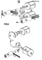
- a gathering is provided by a pair of propellers, substantially comprising brush means, which rotate in opposite directions, intersecting each other, whereby to involve the whole outer surface of core lead coating, whereby to direct the thin wires in a direction perpendicular to the propeller and core lead.
- planes 1, II, III at right angles, through which working takes place may be two: I and II.
- plane III may be surrogated, by tur-ning of cable 0723, by 90 degrees, around its axis 600.
- the system comprises at least three devices 50, 53, 54, providing along at least two planes I and III, at right angles each other, at least four steps: two of twisting (devices 53 and 54), one of gathering and one of stripping.
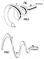
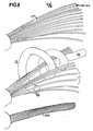
- a propeller 8 comprises an hel icoidal spiral, at least partially conical, made of steel section 88 (figures 6 and 8) round in cross-section or having at least a vertex 91', 92', 93', 94', 95', comprising a sharp edge or blade, (figures 7, 9, 10, 11, 12 and 13), providing stripping (figura 9) and/or twisting fgiure 8) of cables 037, 047, 057, character-ized by an outer coating: 03, 04, 05, which may be screened or coaxial (not shown).
- Provision of the screw, starting from a steel section may occur, in a known manner, by a machine for making springs and the like. Thus the description thereof may be omitted. Provision of a blade 91', 92', 93', 94', 95', involves the use of a steel section, having substantially that shape. On the other hand difficulties may arise when an irregular cross-section, particularly when the two poligonal cross-sections do not correspond, at least from the point of view of coupling of screw driving member or axial stem 100, e.g. to a mandrel
- the shaping and grinding process thereof may be effected by a grinding wheel 30, contacting the inner wall of screw 8, to engage the same, in a range substantially included between arrows C, in indefinite contacting positions, three of which are shown: 93, 94, 95.
- Grinding wheel 30 is tooled so as to work with the axis substantially parallel to the axis of screw 8. Obviously, the grinding wheel 30 and/or screw 8 are to be moved through substantially parallel pathways. In this shaping or grinding process, angle alpha is important. According to the present invention, it max be adjusted by adjusting the x parameter in function of y parameter. Whereas the constructive parameters of the propeller are correlated to the lead to be prepared by the following demonstrative relation:
- Propeller 8 is a screw extending at least along a 270 degrees angle and preferably comprising two or more turns which are made of section which may be of any cross section and as the stem 100 is to be connected to a driving means, such as a mandrel, not shown it is advisable that the section 88, is of circular cross-section.
- a driving means such as a mandrel
- the section 88 is of circular cross-section.
- the cable 037 stands in the same conditions as the cable only to be twisted and, thus, in the same manner is twisted.
- a support is provided which is more affidable than rod 100 and distinctly by the adjacent beveled end of a proper sleeve 109.
- propeller 6 and 6' are in the form of brushes or combs, having radial blades or projections, 60 and 60' respectively in the form of bristles or teeth, whose points or centifugal ends intersect, one another as, the sum of their radial extension is lengther than the distance between the propeller axes 6 and 6'.
- radial extensions 60, 60' in the form of bristles, blades or teeth, made of resilient, deformable material are substantially cilindrical but of different diameters. In detail , they have an encreasing trend, as regards as their bending moment, starting from the ends 61, 61' far from driving motors 18, 18 or from axial point 61, 61' of propellers 6, and 6'. This for the reason that the wires to be arranged, being in the form of a brush, even if very thin, function as a semibeam and thus, at their pointed ends, have a higher compliance and thus require thinner ''bristles" 60, 60' or at any rate, with a higher bending moment.
- wires 7 are generally made of copper i.e. of a yielding unelastic material, they are, unidirectionally brushed or combed, as shown in the drawings. Obviously the bristle dimension and their intersecting length depends from the size of central leads 03, 03' covered by outer coating walls 0, 0' .
Landscapes
- Removal Of Insulation Or Armoring From Wires Or Cables (AREA)
- Piezo-Electric Or Mechanical Vibrators, Or Delay Or Filter Circuits (AREA)
Applications Claiming Priority (6)
| Application Number | Priority Date | Filing Date | Title |
|---|---|---|---|
| IT8364483 | 1983-12-29 | ||
| ITVA1983U60960U IT8360960U1 (it) | 1983-12-29 | 1983-12-29 | Dispositivo ad almeno due giranti, sostanzialmente tangenziali, con raggi a mo' di setole interagenti, particolarmente per la specificazione dei fili esterni, emergenti dalla spellatura dei conduttori, particolarmente schermati e coassiali, sotto forma di treccia normale al conduttore |
| IT6096083U | 1983-12-29 | ||
| IT8383643A IT8383643A0 (it) | 1983-12-29 | 1983-12-29 | Complesso di attrezzi eprocedimento per effettuare, almeno semiautomaticamente, lapreparazione al collegamento dei conduttori elettrici a treccia, particolarmente quelli schermati e coassiali. |
| IT8364383 | 1983-12-29 | ||
| IT8383644A IT1209055B (it) | 1983-12-29 | 1983-12-29 | Girante a spirale elicoidale, almeno parzialmente conica, particolarmente provvista di almeno un utensile a lama, per spellatura e/o l'attorcigliatura dei conduttori a treccia schermati e coassiali e procedimento per laproduzione ed affilatura della stessa. |
Publications (2)
| Publication Number | Publication Date |
|---|---|
| EP0148154A2 true EP0148154A2 (de) | 1985-07-10 |
| EP0148154A3 EP0148154A3 (de) | 1987-10-14 |
Family
ID=27273740
Family Applications (1)
| Application Number | Title | Priority Date | Filing Date |
|---|---|---|---|
| EP85100042A Withdrawn EP0148154A3 (de) | 1983-12-29 | 1985-01-02 | Verfahren und Mittel zum Entmanteln und Verseilen des Endes elektrischer Leitungen |
Country Status (1)
| Country | Link |
|---|---|
| EP (1) | EP0148154A3 (de) |
Cited By (8)
| Publication number | Priority date | Publication date | Assignee | Title |
|---|---|---|---|---|
| EP0263127B1 (de) * | 1986-03-11 | 1991-02-27 | Nokia Data Systems AB | Vorrichtung und verfahren zum formen einer kabelhülle, bestehend aus einer deckschicht, einer gewirkten hülle und leitern |
| DE4212805C1 (en) * | 1992-04-16 | 1993-09-02 | Ks-Konstruktion Gmbh, 91301 Forchheim, De | Coaxial cable end section mfg. method e.g. for fitting to electrical terminal - uses axial displacement and rotation of removal sleeve section of cable outer section |
| CH683645A5 (de) * | 1991-11-12 | 1994-04-15 | Jiri Stepan | Abisoliervorrichtung für Glasfaserkabel. |
| CN107919601A (zh) * | 2018-01-08 | 2018-04-17 | 深圳市原创自动化设备有限公司 | 一种屏蔽线材尾端自动脱皮扭线处理机 |
| CN109936039A (zh) * | 2019-03-26 | 2019-06-25 | 东莞市三信精密机械有限公司 | 防弹丝分离设备和方法 |
| CN110311282A (zh) * | 2019-07-11 | 2019-10-08 | 台州浩然机械制造有限公司 | 一种led焊接端子压着机及绞线焊接方法 |
| CN116174368A (zh) * | 2023-03-05 | 2023-05-30 | 牟维维 | 一种电力检测方法 |
| EP4614739A1 (de) * | 2024-03-05 | 2025-09-10 | MD ELEKTRONIK GmbH | Verfahren und vorrichtung zum bürsten von schirmgeflecht einer leitung |
Family Cites Families (2)
| Publication number | Priority date | Publication date | Assignee | Title |
|---|---|---|---|---|
| JPS4843702B1 (de) * | 1966-11-29 | 1973-12-20 | ||
| US4019409A (en) * | 1975-08-04 | 1977-04-26 | Lyall Electric, Inc. | Stripping and defillering method and apparatus |
-
1985
- 1985-01-02 EP EP85100042A patent/EP0148154A3/de not_active Withdrawn
Cited By (11)
| Publication number | Priority date | Publication date | Assignee | Title |
|---|---|---|---|---|
| EP0263127B1 (de) * | 1986-03-11 | 1991-02-27 | Nokia Data Systems AB | Vorrichtung und verfahren zum formen einer kabelhülle, bestehend aus einer deckschicht, einer gewirkten hülle und leitern |
| CH683645A5 (de) * | 1991-11-12 | 1994-04-15 | Jiri Stepan | Abisoliervorrichtung für Glasfaserkabel. |
| DE4212805C1 (en) * | 1992-04-16 | 1993-09-02 | Ks-Konstruktion Gmbh, 91301 Forchheim, De | Coaxial cable end section mfg. method e.g. for fitting to electrical terminal - uses axial displacement and rotation of removal sleeve section of cable outer section |
| CN107919601A (zh) * | 2018-01-08 | 2018-04-17 | 深圳市原创自动化设备有限公司 | 一种屏蔽线材尾端自动脱皮扭线处理机 |
| CN107919601B (zh) * | 2018-01-08 | 2024-06-11 | 深圳市原创自动化设备有限公司 | 一种屏蔽线材尾端自动脱皮扭线处理机 |
| CN109936039A (zh) * | 2019-03-26 | 2019-06-25 | 东莞市三信精密机械有限公司 | 防弹丝分离设备和方法 |
| CN110311282A (zh) * | 2019-07-11 | 2019-10-08 | 台州浩然机械制造有限公司 | 一种led焊接端子压着机及绞线焊接方法 |
| CN110311282B (zh) * | 2019-07-11 | 2024-04-23 | 台州浩然机械制造有限公司 | 一种led焊接端子压着机及绞线焊接方法 |
| CN116174368A (zh) * | 2023-03-05 | 2023-05-30 | 牟维维 | 一种电力检测方法 |
| EP4614739A1 (de) * | 2024-03-05 | 2025-09-10 | MD ELEKTRONIK GmbH | Verfahren und vorrichtung zum bürsten von schirmgeflecht einer leitung |
| DE102024106262A1 (de) * | 2024-03-05 | 2025-09-11 | Md Elektronik Gmbh | Verfahren und vorrichtung zum bürsten von schirmgeflecht einer leitung |
Also Published As
| Publication number | Publication date |
|---|---|
| EP0148154A3 (de) | 1987-10-14 |
Similar Documents
| Publication | Publication Date | Title |
|---|---|---|
| US8790116B2 (en) | Endodontic file | |
| US4019409A (en) | Stripping and defillering method and apparatus | |
| US6141818A (en) | Brush for gum massage and tooth cleaning and process for producing the bristles of such a brush | |
| DE102018208407A1 (de) | Verfahren zur Herstellung von Formlitze, Verfahren zur Herstellung eines Elektromotors, sowie Verwendung von Formlitze | |
| EP1549173B1 (de) | Wimperntuschebürstchen mit drahtkern | |
| CN1266359A (zh) | 松弛丝端部倒圆的方法 | |
| US2472510A (en) | Wire twisting device | |
| JPH11504799A (ja) | ストリッパ | |
| WO2008028079A2 (en) | Wire-twisting tool and related method | |
| CN209233133U (zh) | 自动化排线端子设备 | |
| JPS6481608A (en) | Terminating device for covered conductor | |
| JPS63284780A (ja) | 対撚り集合ケ−ブルの心線分離機構 | |
| CN209169809U (zh) | 一种应用于建筑工程电气施工室内线缆并线的绞线工具 | |
| EP0148154A3 (de) | Verfahren und Mittel zum Entmanteln und Verseilen des Endes elektrischer Leitungen | |
| KR102546362B1 (ko) | 퀵 타입 와이어 컨넥터 | |
| CN214123585U (zh) | 半自动绞线装置 | |
| JPH09311259A (ja) | ケーブル端末の切削方法及び切削工具 | |
| JPS5837997Y2 (ja) | エンスイコイルジヨウ シユウゴウヨリアワセダイス | |
| JPH0545059Y2 (de) | ||
| JPS6120823Y2 (de) | ||
| SU1665447A1 (ru) | Ручной инструмент дл сн ти изол ции с концов проводов | |
| CN208939318U (zh) | 水晶头制作用工具 | |
| CN212033409U (zh) | 一种护套软电缆剥线钳 | |
| JPH0118641B2 (de) | ||
| WO1995028755A1 (de) | Verfahren und vorrichtung zur erzeugung eines festen litzenendes sowie litze |
Legal Events
| Date | Code | Title | Description |
|---|---|---|---|
| PUAI | Public reference made under article 153(3) epc to a published international application that has entered the european phase |
Free format text: ORIGINAL CODE: 0009012 |
|
| AK | Designated contracting states |
Designated state(s): AT BE CH DE FR GB IT LI LU NL SE |
|
| PUAL | Search report despatched |
Free format text: ORIGINAL CODE: 0009013 |
|
| AK | Designated contracting states |
Kind code of ref document: A3 Designated state(s): AT BE CH DE FR GB IT LI LU NL SE |
|
| STAA | Information on the status of an ep patent application or granted ep patent |
Free format text: STATUS: THE APPLICATION IS DEEMED TO BE WITHDRAWN |
|
| 18D | Application deemed to be withdrawn |
Effective date: 19870202 |