EP0148182B1 - Procede et appareil pour la separation discontinue centrifuge de sang - Google Patents
Procede et appareil pour la separation discontinue centrifuge de sang Download PDFInfo
- Publication number
- EP0148182B1 EP0148182B1 EP83903842A EP83903842A EP0148182B1 EP 0148182 B1 EP0148182 B1 EP 0148182B1 EP 83903842 A EP83903842 A EP 83903842A EP 83903842 A EP83903842 A EP 83903842A EP 0148182 B1 EP0148182 B1 EP 0148182B1
- Authority
- EP
- European Patent Office
- Prior art keywords
- container
- blood
- casing
- receiving chamber
- constriction
- Prior art date
- Legal status (The legal status is an assumption and is not a legal conclusion. Google has not performed a legal analysis and makes no representation as to the accuracy of the status listed.)
- Expired
Links
- 210000004369 blood Anatomy 0.000 title claims abstract description 63
- 239000008280 blood Substances 0.000 title claims abstract description 63
- 238000000926 separation method Methods 0.000 title claims abstract description 13
- 238000000034 method Methods 0.000 title claims description 12
- 238000005119 centrifugation Methods 0.000 claims abstract description 22
- 238000005534 hematocrit Methods 0.000 claims abstract description 11
- 238000003466 welding Methods 0.000 claims description 8
- 238000002955 isolation Methods 0.000 claims description 7
- 238000007789 sealing Methods 0.000 claims description 5
- 238000004891 communication Methods 0.000 claims description 4
- 230000002706 hydrostatic effect Effects 0.000 claims description 3
- 239000000463 material Substances 0.000 claims description 3
- 238000013517 stratification Methods 0.000 claims 1
- 239000000945 filler Substances 0.000 abstract description 15
- 230000008707 rearrangement Effects 0.000 abstract 1
- 210000003743 erythrocyte Anatomy 0.000 description 24
- 210000002381 plasma Anatomy 0.000 description 16
- 210000001624 hip Anatomy 0.000 description 8
- 230000004048 modification Effects 0.000 description 5
- 238000012986 modification Methods 0.000 description 5
- 210000000601 blood cell Anatomy 0.000 description 4
- 230000009471 action Effects 0.000 description 3
- 238000007792 addition Methods 0.000 description 2
- 230000015572 biosynthetic process Effects 0.000 description 2
- 238000010276 construction Methods 0.000 description 2
- 239000012611 container material Substances 0.000 description 2
- 238000006073 displacement reaction Methods 0.000 description 2
- 230000000694 effects Effects 0.000 description 2
- 238000011049 filling Methods 0.000 description 2
- 238000005755 formation reaction Methods 0.000 description 2
- 238000003780 insertion Methods 0.000 description 2
- 230000037431 insertion Effects 0.000 description 2
- 230000009467 reduction Effects 0.000 description 2
- 238000009987 spinning Methods 0.000 description 2
- GFFGJBXGBJISGV-UHFFFAOYSA-N Adenine Chemical compound NC1=NC=NC2=C1N=CN2 GFFGJBXGBJISGV-UHFFFAOYSA-N 0.000 description 1
- 229930024421 Adenine Natural products 0.000 description 1
- WQZGKKKJIJFFOK-GASJEMHNSA-N Glucose Natural products OC[C@H]1OC(O)[C@H](O)[C@@H](O)[C@@H]1O WQZGKKKJIJFFOK-GASJEMHNSA-N 0.000 description 1
- FAPWRFPIFSIZLT-UHFFFAOYSA-M Sodium chloride Chemical compound [Na+].[Cl-] FAPWRFPIFSIZLT-UHFFFAOYSA-M 0.000 description 1
- 239000000654 additive Substances 0.000 description 1
- 229960000643 adenine Drugs 0.000 description 1
- 230000004075 alteration Effects 0.000 description 1
- 239000003146 anticoagulant agent Substances 0.000 description 1
- 229940127219 anticoagulant drug Drugs 0.000 description 1
- WQZGKKKJIJFFOK-VFUOTHLCSA-N beta-D-glucose Chemical compound OC[C@H]1O[C@@H](O)[C@H](O)[C@@H](O)[C@@H]1O WQZGKKKJIJFFOK-VFUOTHLCSA-N 0.000 description 1
- 239000012503 blood component Substances 0.000 description 1
- 239000012141 concentrate Substances 0.000 description 1
- 239000013536 elastomeric material Substances 0.000 description 1
- 239000012530 fluid Substances 0.000 description 1
- 210000003918 fraction a Anatomy 0.000 description 1
- 238000005194 fractionation Methods 0.000 description 1
- 239000008103 glucose Substances 0.000 description 1
- 238000010438 heat treatment Methods 0.000 description 1
- 238000011068 loading method Methods 0.000 description 1
- 238000002616 plasmapheresis Methods 0.000 description 1
- 239000002985 plastic film Substances 0.000 description 1
- 229920006255 plastic film Polymers 0.000 description 1
- 238000004904 shortening Methods 0.000 description 1
- 239000011780 sodium chloride Substances 0.000 description 1
- 238000012546 transfer Methods 0.000 description 1
- 230000007704 transition Effects 0.000 description 1
Images

Classifications
-
- A—HUMAN NECESSITIES
- A61—MEDICAL OR VETERINARY SCIENCE; HYGIENE
- A61M—DEVICES FOR INTRODUCING MEDIA INTO, OR ONTO, THE BODY; DEVICES FOR TRANSDUCING BODY MEDIA OR FOR TAKING MEDIA FROM THE BODY; DEVICES FOR PRODUCING OR ENDING SLEEP OR STUPOR
- A61M1/00—Suction or pumping devices for medical purposes; Devices for carrying-off, for treatment of, or for carrying-over, body-liquids; Drainage systems
- A61M1/02—Blood transfusion apparatus
- A61M1/029—Separating blood components present in distinct layers in a container, not otherwise provided for
-
- A—HUMAN NECESSITIES
- A61—MEDICAL OR VETERINARY SCIENCE; HYGIENE
- A61M—DEVICES FOR INTRODUCING MEDIA INTO, OR ONTO, THE BODY; DEVICES FOR TRANSDUCING BODY MEDIA OR FOR TAKING MEDIA FROM THE BODY; DEVICES FOR PRODUCING OR ENDING SLEEP OR STUPOR
- A61M1/00—Suction or pumping devices for medical purposes; Devices for carrying-off, for treatment of, or for carrying-over, body-liquids; Drainage systems
- A61M1/02—Blood transfusion apparatus
- A61M1/0272—Apparatus for treatment of blood or blood constituents prior to or for conservation, e.g. freezing, drying or centrifuging
- A61M1/0277—Frames constraining or supporting bags, e.g. during freezing
-
- B—PERFORMING OPERATIONS; TRANSPORTING
- B04—CENTRIFUGAL APPARATUS OR MACHINES FOR CARRYING-OUT PHYSICAL OR CHEMICAL PROCESSES
- B04B—CENTRIFUGES
- B04B5/00—Other centrifuges
- B04B5/04—Radial chamber apparatus for separating predominantly liquid mixtures, e.g. butyrometers
- B04B5/0407—Radial chamber apparatus for separating predominantly liquid mixtures, e.g. butyrometers for liquids contained in receptacles
- B04B5/0428—Radial chamber apparatus for separating predominantly liquid mixtures, e.g. butyrometers for liquids contained in receptacles with flexible receptacles
Definitions
- This invention relates to centrifugal separation of blood, namely, centrifugal batch separation of blood in a closed collapsible blood container and subsequent isolation of the centrifugally formed fractions.
- the present predominant technique for centrifugal batch separation of blood comprises use of a collapsible main container holding whole blood to be separated and one or more initially empty auxiliary containers connected with the main container through flexible conduits.
- the blood is separated into a heavier fraction comprising the main portion of the erythrocytes (the red blood cells) of the batch of blood confined in the main container, and a lighter fraction mainly consisting of plasma.
- a single auxiliary container is used in this case.
- Other cases may comprise separation of the blood into additional fractions, such as fraction constituting the so-called buffy-coat, which includes the main portion of the platelets and is of a density lower than that of the erythrocyte fraction but higher than that of the plasma fraction. Consequently, upon completed centrifugation, the buffy-coat fraction, which amounts to a very small portion, one percent or so, of the total blood volume, is positioned between the plasma fraction and the erythrocyte fraction in the container.
- a second auxiliary container is used into which that fraction is squeezed after the plasma fraction has been transferred to the first auxiliary container and the connecting conduit of the latter has been closed.
- centrifugal batch separation is a technique involving use of a single elongate blood container which is filled with a predetermined quantity of blood and then placed in a centrifuge rotor and centrifuged until the blood has been divided into two or more fractions.
- the blood container In order to isolate the various fractions in the container from each other upon completion of the centrifugation, the blood container is pinched in the region of the interface of adjoining fractions, and it is also known to render the isolation achieved through the pinching permanent by welding the container walls together at the pinched region or regions. Then the blood container may be severed at the welded region or regions so that separate container sections containing different fractions are obtained.
- An object of the invention is to make it possible in a simple way to isolate the centrifugally formed fractions in an elongate container from each other with a minimum of intermixing of adjoining portions of the fractions.
- the sepration is carried out in accordance with claim 1 and using the device defined in claim 7, the features of the respective precharacterising parts being known from US-A-3 545 671.
- the closing of the passages between the container compartments is effected while the container is in the casing, preferably while the blood is still subjected to a certain centrifugal force, and without substantial alteration of the shape of the container.
- the container is constricted at the regions where the interfaces of the fractions will be located, so that only a relatively small movement of the container walls is required for closing the passages between adjoining container sections holding different fractions.
- the closing operation aiming at isolating the erythrocyte fraction, i.e., the fraction that occupies the radially outermost position in the centrifuge, from the inwardly next adjacent fraction, may always be effected exactly at the desired position, at the interface of the fractions, even if the volume of the batch of blood confined in the container and the hematocrit of the blood (the ratio of the erythrocyte volume to the total volume) varies from batch to batch, the total volume and the hematocrit of each batch is determined before the centrifugation is carried out, whereupon, if necessary, the volumetric capacity of the container section intended for receiving the erythrocyte fraction is adjusted according to the product of the hematocrit and the total volume. The adjustment of the volumetric capacity is effected such that the closing is always effected at the same position on all containers.
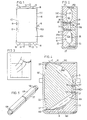
- the blood container 10 shown in Fig. 1 is made in accordance with known techniques by welding together two rectangular pieces of plastic film.
- a number of flexible conduits for introducing blood and any additives (such as anticoagulant) and for withdrawing blood components namely, a filling conduit 12 through which blood is introduced into the container, an erythrocyte conduit 13 through which the erythrocyte fraction may be withdrawn, a plasma conduit 14 through which the plasma fraction may be withdrawn, and a buffy-coat conduit 15 through which the buffy-coat fraction may be withdrawn.
- the intermediate portion of the container has a pair of "waists" 16 and 17 on opposite sides of the region where the buffy-coat conduit 15 is connected. These waists are positioned where after completed centrifugation the blood fractions are isolated from each other. They also form a transition between three sections 10A, 10B and 10C of the container. Of these sections, the two outer or end sections 10A and 10C are of approximately the same size and intended to hold respectively the erythrocyte fraction and the plasma fraction. The intermediate section 10B, which is intended to hold the buffy-coat fraction, is very small compared with the two other sections.
- the container is intended to be filled with about 500 ml of blood and is dimensioned to be able to receive that quantity of blood without becoming firmly expanded.
- each of the two outer sections 10A and 10C is approximately square and its thickness is small compared to its length and width.
- Each end of the container 10 comprises a tab 18 formed with a pair of mounting holes 19.
- the container When the batch of blood introduced into the container 10 is to be separated, the container is inserted in the flat cassette-like casing 20 shown diagrammatically in Fig. 2 which is then inserted in a cup-shaped receptacle 21.
- This receptacle forms part of a centrifuge rotor, not shown, in which the receptacle is positioned eccentrically and arranged such that during the centrifugation its longitudinal axis or central plane includes an angle with the axis of rotation of the rotor.
- the casing 20 is rigid so that it is capable of carrying the forces resulting from the centrifugation without undergoing substantial deformation.
- the casing comprises two halves 22 and 23 which can be coupled together and which define between them a container receiving chamber 25 of the flat cross-sectional shape shown in Fig. 2.
- the extension of the container receiving chamber transversely of the plane of Fig. 2 is matched with the width of the filled container 10.
- the container receiving chamber 25 has a pair of constrictions dividing the chamber into three compartments 25A, 25B, 25C for receiving respectively the container sections 10A, 10B and 10C.
- each container wall engages the casing surface defining the container receiving chamber 25; only at the end of the casing positioned at the mouth of the receptacle 21 is there a region 25D where the container wall is not firmly supported by the casing.
- a portion of the casing wall engaging the container 10 is formed by a removable filler body 26.
- This filler body 26 is sized such that the volume accommodated in the compartment 25A or, more precisely, in the container section 10A received therein, as nearly as possible equals the combined volume of the erythrocytes contained in the blood, that is, the product of the hematocrit and the total volume of the blood in the container.
- the volume and the hematocrit must be determined and an appropriate filler body 26 positioned in the container receiving chamber of the casing.
- the selection of the filler body may be made with the help of the nomogram of Fig. 3 where the vertical axis represents the hematocrit while the curves 28a represent different volumes.
- the filler body best suited for the occasion is the filler body marked on the horizontal axis vertically below the intersection of the applicable volume curve and a horizontal line drawn from the determined hematocrit on the vertical axis.
- the volume of the compartment 25A of the container receiving chamber 25 may also be adjusted in ways other than by insertion of different filler bodies.
- a portion of a wall defining the compartment may be movable and adjustable by means of an adjusting device on the casing.
- casings of non-adjustable volume the matching with the determined blood volume being made by selection of a casing the compartment 25A of which is of the appropriate volume.
- the holes 19 of the container tabs are engaged over a number of pegs 27 secured to the casing half 22A.
- the conduits 12 and 15 and their connectors are engaged in recesses in one or both of the casing halves.
- the pressure bars 28 and the backing bars 29, which in the illustrated embodiment extend across the entire container receiving chamber 25, are also adapted to serve as welding or heat sealing jaws and to this end are provided with electrical heaters, high frequency heating electrodes or other suitable heat sealing means and associated terminals 31 for a separate source of electrical energy.
- these terminals are only symbolically shown in Fig. 2.
- the centrifugally produced hydrostatic pressure within the container 10 causes a slight displacement of the pressure bars 28 outwardly against the spring loading.
- a gap extending across the width of the container and having a width of one or a few millimetres will be formed at each waist 16, 17 of the container, so that the three container sections 10A, 10B, 10C are placed in open communication.
- the contents of the container can thereby be rearranged to form three main fractions, namely, an erythrocyte fraction in the radially outermost container section 10A, a buffy-coat fraction in the intermediate container section 10B and a plasma fraction in the radially innermost container section 10C.
- the springs 30 will again close the gaps between the container sections when a predetermined speed controlled by, for example, the spring force is reached.
- the resulting movement of one of the container walls is very small and restricted to the region immediately adjacent the pressure bars 28, so that the centrifugally produced separation of the blood into fractions is disturbed very little.
- the casing 20 is removed from the receptacle 21, whereupon the terminals 31 are connected to a source of electrical energy for welding or heat sealing together the opposed container walls at the waists 16 and 17, so that the isolation of the fractions from each other resulting from the pinching of the container walls is made permanent.
- the container can then be taken out of the casing and, if desired, cut off at the waists so that each container section 10A, 10B, 10C forms a separate container.
- the three flat container sections 10A, 10B and 10C are disposed in the casing 120 such that their general planes include an angle with each other; in the figure the general planes A, B and C are represented by phantom lines.
- the general planes A and C of the container sections 10A and 10C are disposed such that they include an angle of 30°-60° with the direction of the centrifugal force during the centrifugation, while the general plane B of the container section 10B is oriented substantially in the direction of the centrifugal force.
- the angled position of the container sections 10A and 10C reduces the requirement for space in the direction of the centrifugal force so that a commercially available centrifuge having pivoted container receptacles can be used, and at the same time the angle effect results in an efficient fractionation.
- a great distance of separation in the container compartment is obtained.
- the casing 120 is formed by two halves 122 and 123, which are joined at a hinge 135.
- the container 10 is again secured to pegs 127 on the casing half 122, but instead of pinching devices permanently positioned in the casing there is a pair of pinch bars 136, 137 which are loosely inserted in recesses in the casing halves 122 and 123.
- These pinch bars are positioned in the casing on opposite sides of the blood container 10 at the container waists 16 and 17 and extend across the width of the container. They may be unbiassed or biassed towards the container by resilient members.
- gap-like passages are opened between the sections during the centrifugation, the opening of the passages taking place under the action of the hydrostatic pressure. If the pinch bars are unbiassed, the passages are closed upon completion of the centrifugation by applying clamping rings 138 over the ends of the pinch bars, see Fig. 5.
- the closing of the passages, and consequently the isolation of the fractions from each other is effected while the centrifuge rotor is spinning, that is, while the centrifugal force is still contributing to maintaining the separation into fractions.
- the closing has to take place while the container is in the casing and without the container walls undergoing large relative movements.
- the casing after it has been taken out of the centrifuge, may be engaged with a suitable auxiliary device effecting the closing before the casing is opened and the container is taken out.
- the various filler bodies 26, 126 for the erythrocyte compartment of the container receiving chamber 25, 125 are dimensioned so that with proper selection of the filler body the interface between the erythrocyte fraction and the buffy-coat fraction is always positioned radially inwardly of the outer pinching position. In corresponding mannerthe radially inner pinching position is located such that it is ensured that substantially all platelets will be confined in the buffy-coat section.
- the passages at the blood container waists 16 and 17 extend across substantially the entire width of the container.
- shape the container such that the passages only extend across a portion of the container. This can be done by welding together the opposed container walls over a larger or smaller portion of the width of the container when the container is produced.
- the blood container can be modified to suit the so-called SAG system.
- SAG solution saline, adenine and glucose
- the blood container is provided adjacent the erythrocyte section 10A with a closed container section filled with SAG solution (saline, adenine and glucose) from which, upon completion of the centrifugation and isolation of the erythrocyte fraction, the solution is transferred to the erythrocyte section to be mixed with the erythrocytes therein.
- SAG solution serum, adenine and glucose
- the blood container 10 may be provided with an internal conduit one end of which is in constant open communication with the erythrocyte section 10A and the other end of which is in constant open communication with the plasma section 10C.
- Such a conduit has been indicated in phantom lines at 40 in Fig. 1.
- the closing of the passages between the container sections is effected in such a way that a certain amount of plasma may be squeezed over from the plasma section into the erythrocyte section by way of the conduit, which can then be closed, such as by welding at the passages.
- the pressure bars 28 or 29 or the pinch bars 136 or 137 may be provided with recesses at the points where the conduit is situated during the centrifugation.
- the embodiment shown in Fig. 4 may be replaced by an embodiment based on the arrangements diagrammatically shown in Figs. 6 to 10.
- a characterising feature of these arrangements is that the thickness of the filled container, that is, its largest horizontal dimension as measured in Fig. 6, is substantially larger than the corresponding dimension in Fig. 2.
- the blood container 210 in a manner similar to that shown in Fig. 2 is enclosed in a cassette-like casing 220 during the centrifugation, which casing is inserted in a cup-like receptacle 221 forming part of a centrifuge rotor, not shown, in which the receptacle is pivotable about a horizontal axis. This axis is indicated at T in Fig. 6.
- the casing 220 is again rigid and formed of two halves 222 and 223 which can be joined and clamped together and which define a container receiving chamber 225 the shape of which is assumed by the filled container 210 when it is enclosed in the casing.
- the casing halves 222 and 223 are provided with movable pressure bars 228 and stationary backing bars 229 substantially corresponding to the pressure bars and the backing bars of Fig. 2.
- a lining 222A and 223A of an elastomeric material having a density greater than that of blood is applied to the outer side of the casing halves 222 and 223 .
- the casing 220 fits the receptacle 221 with a clearance that is just about sufficient to permit ready insertion and removal of the casing from the receptacle.
- the lining material will be slightly displaced inwardly in the receptacle and thereby cause the casing halves to be clamped together.
- the lining may also be applied to the inner side of the receptacle.
- One casing half 222 is provided with four parallel clamping and guiding pins 227 extending into the other casing half 223. These guiding pins serve the purpose of properly locating the casing halves relative to each other when the halves are joined together and to holding, in cooperation with clamping elements (not shown), the halves clamped together.
- Each guiding pin 227 passes through a ridge formation provided in the casing halves 222 and 223 and having a generally triangular cross-section. These ridge formations are shown at 223B and 223C in Fig. 7 for the casing half 223.
- the flanks F, G, H, I of these ridges form a support for the portions of the container 210 situated between, on the one hand, each ridge crest, and, on the other hand, the adjacent container end and the adjacent pair of pressure and backing bars.
- These flanks which need not necessarily be of the illustrated flat shape, include an angle a 1 (Fig.
- the cross-sectional area of the container can be maximized so that the length of the casing can be minimized. This can be done without consequent great risk of an undesired creasing and stretching of the container material and without the inclined surfaces including so large an angle with the direction of the centrifugal field that the blood cells tend to stick.
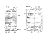
- FIG. 9 only shows the two parts 322 and 323 of the casing 320 and the container 310 placed between these parts.
- the casing 320 formed by the parts 322 and 323 has, in the lower compartment 325A of the container receiving chamber, a ridge- shaped filler body 340 and a similarfiller body 341 in the upper compartment 325B.
- the two filler bodies 340 and 341 extend across the container receiving chamber parallel to the guide pins 327 and symmetrically with respect to the central plane S.
- the volume of the lower compartment 325A of the container receiving chamber may be matched in the above-described manner with the volume and hematocrit of the blood to be separated.
- positions and shapes of the filler bodies other than those shown may be used.
- the container 310 used in Figs. 9, 10 resembles the blood container of Figs. 6 to 8 apart from the fact that the end portions are slightly tapered.
- the upper and the lower compartment of the container receiving chamber may be shaped as a tetrahedron one edge of which extends along the adjacent pair of pressure and backing bars, that is, in the central plane R, while a further edge at the end of the container extends in the central plane S.
- the blood container is constricted at two positions so that the buffy-coat fraction may be isolated from the erythrocyte and plasma fractions.
- the buffy-coat fraction may be isolated from the erythrocyte and plasma fractions.
Landscapes
- Health & Medical Sciences (AREA)
- Heart & Thoracic Surgery (AREA)
- Vascular Medicine (AREA)
- Engineering & Computer Science (AREA)
- Anesthesiology (AREA)
- Biomedical Technology (AREA)
- Hematology (AREA)
- Life Sciences & Earth Sciences (AREA)
- Animal Behavior & Ethology (AREA)
- General Health & Medical Sciences (AREA)
- Public Health (AREA)
- Veterinary Medicine (AREA)
- Pathology (AREA)
- Centrifugal Separators (AREA)
- External Artificial Organs (AREA)
Abstract
Claims (13)
caractérisé en ce que
Priority Applications (1)
| Application Number | Priority Date | Filing Date | Title |
|---|---|---|---|
| AT83903842T ATE32984T1 (de) | 1982-11-26 | 1983-11-28 | Verfahren und vorrichtung zum chargenweise zentrifugaltrennen von blut. |
Applications Claiming Priority (2)
| Application Number | Priority Date | Filing Date | Title |
|---|---|---|---|
| SE8206767 | 1982-11-26 | ||
| SE8206767A SE8206767D0 (sv) | 1982-11-26 | 1982-11-26 | Sett och anordning for satsvis centrifugalseparering av blod |
Publications (2)
| Publication Number | Publication Date |
|---|---|
| EP0148182A1 EP0148182A1 (fr) | 1985-07-17 |
| EP0148182B1 true EP0148182B1 (fr) | 1988-03-16 |
Family
ID=20348765
Family Applications (1)
| Application Number | Title | Priority Date | Filing Date |
|---|---|---|---|
| EP83903842A Expired EP0148182B1 (fr) | 1982-11-26 | 1983-11-28 | Procede et appareil pour la separation discontinue centrifuge de sang |
Country Status (7)
| Country | Link |
|---|---|
| US (1) | US4617009A (fr) |
| EP (1) | EP0148182B1 (fr) |
| JP (1) | JPS60500126A (fr) |
| AU (1) | AU567710B2 (fr) |
| DE (1) | DE3375979D1 (fr) |
| SE (1) | SE8206767D0 (fr) |
| WO (1) | WO1984002091A1 (fr) |
Families Citing this family (66)
| Publication number | Priority date | Publication date | Assignee | Title |
|---|---|---|---|---|
| US5372945A (en) * | 1985-06-06 | 1994-12-13 | Alchas; Paul G. | Device and method for collecting and processing fat tissue and procuring microvessel endothelial cells to produce endothelial cell product |
| US4714457A (en) * | 1986-09-15 | 1987-12-22 | Robert Alterbaum | Method and apparatus for use in preparation of fibrinogen from a patient's blood |
| US4915847A (en) * | 1987-08-04 | 1990-04-10 | Baxter International Inc. | Cryoglobulin separation |
| US4917804A (en) * | 1986-10-31 | 1990-04-17 | Baxter International Inc. | Method and vessel for separation of cryoglobin |
| US5076911A (en) * | 1987-01-30 | 1991-12-31 | Baxter International Inc. | Centrifugation chamber having an interface detection surface |
| US6780333B1 (en) | 1987-01-30 | 2004-08-24 | Baxter International Inc. | Centrifugation pheresis method |
| US5104526A (en) * | 1987-01-30 | 1992-04-14 | Baxter International Inc. | Centrifugation system having an interface detection system |
| US4940543A (en) * | 1987-01-30 | 1990-07-10 | Baxter International Inc. | Plasma collection set |
| US4834890A (en) * | 1987-01-30 | 1989-05-30 | Baxter International Inc. | Centrifugation pheresis system |
| US4806252A (en) * | 1987-01-30 | 1989-02-21 | Baxter International Inc. | Plasma collection set and method |
| US5078671A (en) * | 1988-10-07 | 1992-01-07 | Baxter International Inc. | Centrifugal fluid processing system and method |
| US4936820A (en) * | 1988-10-07 | 1990-06-26 | Baxter International Inc. | High volume centrifugal fluid processing system and method for cultured cell suspensions and the like |
| DE8902975U1 (de) * | 1989-03-10 | 1990-04-19 | Fa. Andreas Hettich, 7200 Tuttlingen | Einsatzbecher für Zentrifugen |
| US5102407A (en) * | 1990-03-13 | 1992-04-07 | Miles Inc. | Blood separation system |
| SE9002255D0 (sv) * | 1990-06-26 | 1990-06-26 | Eric Westberg | Metod och anordning vid framstaellning av blod |
| US5154716A (en) * | 1990-11-06 | 1992-10-13 | Miles Inc. | Bottom blood bag separation system |
| SE469211B (sv) * | 1992-04-23 | 1993-06-07 | Seroteknik Handelsbolag C O Er | System och foerfarande foer centrifugalseparering av tvaa eller flera fraktioner fraan en sammansatt vaetska samt daerfoer avsedd paase med medel att straecka paasen foer att avdela |
| US5656154A (en) * | 1995-06-07 | 1997-08-12 | Organ, Inc. | Method and apparatus for separating a fluid into components and for washing a material |
| SE9700495D0 (sv) | 1997-02-12 | 1997-02-12 | Omega Medicinteknik Ab | Metod och rundpåsesystem samt centrifug för behandling av blod |
| US6019716A (en) * | 1998-07-13 | 2000-02-01 | Novartis Ag | Centrifuge bag-holding device with clamp assembly and uses thereof |
| US6123696A (en) * | 1998-07-16 | 2000-09-26 | Thermogenesis Corp. | Centrifugation bag with yieldable partitions |
| US6695803B1 (en) | 1998-10-16 | 2004-02-24 | Mission Medical, Inc. | Blood processing system |
| AU2006203221B2 (en) * | 1999-05-31 | 2008-06-05 | Terumo Bct, Inc. | Centrifuge for processing blood and blood components in ring type blood processing |
| SE516321C2 (sv) * | 1999-05-31 | 2001-12-17 | Gambro Inc | Centrifug för behandling av blod och blodkomponenter |
| SE517032C2 (sv) | 1999-10-26 | 2002-04-02 | Gambro Inc | Sätt och anordning för behandling av blod och blodkomponenter |
| DE10065283A1 (de) | 2000-12-29 | 2002-07-04 | Hettich Andreas Gmbh & Co Kg | Zentrifuge mit Blutbeutelsystem mit oberem und unterem Abgang |
| US7279107B2 (en) | 2002-04-16 | 2007-10-09 | Gambro, Inc. | Blood component processing system, apparatus, and method |
| US7374678B2 (en) | 2002-05-24 | 2008-05-20 | Biomet Biologics, Inc. | Apparatus and method for separating and concentrating fluids containing multiple components |
| US7992725B2 (en) | 2002-05-03 | 2011-08-09 | Biomet Biologics, Llc | Buoy suspension fractionation system |
| US7832566B2 (en) | 2002-05-24 | 2010-11-16 | Biomet Biologics, Llc | Method and apparatus for separating and concentrating a component from a multi-component material including macroparticles |
| US20030205538A1 (en) | 2002-05-03 | 2003-11-06 | Randel Dorian | Methods and apparatus for isolating platelets from blood |
| US7845499B2 (en) | 2002-05-24 | 2010-12-07 | Biomet Biologics, Llc | Apparatus and method for separating and concentrating fluids containing multiple components |
| US20060278588A1 (en) | 2002-05-24 | 2006-12-14 | Woodell-May Jennifer E | Apparatus and method for separating and concentrating fluids containing multiple components |
| DE10392686T5 (de) | 2002-05-24 | 2005-07-07 | Biomet Mfg. Corp., Warsaw | Vorrichtung und Verfahren zum Trennen und Konzentrieren von Flüssigkeiten, welche mehrere Komponenten enthalten |
| US7866485B2 (en) | 2005-02-07 | 2011-01-11 | Hanuman, Llc | Apparatus and method for preparing platelet rich plasma and concentrates thereof |
| WO2006086199A1 (fr) | 2005-02-07 | 2006-08-17 | Hanuman Llc | Appareil et procede de preparation de concentres de plasma riche en plaquettes |
| WO2006086201A2 (fr) | 2005-02-07 | 2006-08-17 | Hanuman Llc | Appareil et procede de concentration de plasma riche en plaquettes |
| US8048678B2 (en) * | 2005-10-27 | 2011-11-01 | Ecw Therapeutics, Inc. | Cell separation method and apparatus |
| WO2007050986A1 (fr) * | 2005-10-27 | 2007-05-03 | Neil Duffy | Procede et appareil de separation de cellules |
| WO2007101248A2 (fr) * | 2006-02-28 | 2007-09-07 | Levtech, Inc. | Appareil de pompage jetable base sur des recipients flexibles dans des contenants sous pression |
| US8567609B2 (en) | 2006-05-25 | 2013-10-29 | Biomet Biologics, Llc | Apparatus and method for separating and concentrating fluids containing multiple components |
| WO2008127639A1 (fr) | 2007-04-12 | 2008-10-23 | Biomet Biologics, Llc | Système de fractionnement de suspension à flotteur |
| US8328024B2 (en) | 2007-04-12 | 2012-12-11 | Hanuman, Llc | Buoy suspension fractionation system |
| EP2147308A4 (fr) * | 2007-05-23 | 2012-07-25 | Ge Healthcare Bio Sciences Ab | Dispositif de séparation |
| EP2620139B1 (fr) | 2008-02-27 | 2016-07-20 | Biomet Biologics, LLC | Solutions riches d'un antagoniste du récepteur de l'interleukine-1 |
| WO2009111338A1 (fr) * | 2008-02-29 | 2009-09-11 | Biomet Manufacturing Corp. | Système et procédé pour la séparation d'une matière |
| US8012077B2 (en) | 2008-05-23 | 2011-09-06 | Biomet Biologics, Llc | Blood separating device |
| DE102008047068B4 (de) * | 2008-09-12 | 2015-02-26 | Walter Pobitschka | Verfahren und Vorrichtung zur Trennung von Blut unter Einsatz einer Zentrifuge |
| US8309343B2 (en) | 2008-12-01 | 2012-11-13 | Baxter International Inc. | Apparatus and method for processing biological material |
| US8187475B2 (en) | 2009-03-06 | 2012-05-29 | Biomet Biologics, Llc | Method and apparatus for producing autologous thrombin |
| US8313954B2 (en) | 2009-04-03 | 2012-11-20 | Biomet Biologics, Llc | All-in-one means of separating blood components |
| US9011800B2 (en) | 2009-07-16 | 2015-04-21 | Biomet Biologics, Llc | Method and apparatus for separating biological materials |
| US8591391B2 (en) | 2010-04-12 | 2013-11-26 | Biomet Biologics, Llc | Method and apparatus for separating a material |
| US9079194B2 (en) | 2010-07-19 | 2015-07-14 | Terumo Bct, Inc. | Centrifuge for processing blood and blood components |
| DE102011105311A1 (de) | 2011-06-19 | 2012-12-20 | Walter Pobitschka | Verfahren zur Trennung von Blut, Abtrennbehälter für eine Blutzentrifuge, System zur Befüllung eines Einfrierbehälters |
| JP5860326B2 (ja) * | 2012-03-30 | 2016-02-16 | 株式会社ジェイ・エム・エス | 血液成分分離用装置の姿勢保持具 |
| US9642956B2 (en) | 2012-08-27 | 2017-05-09 | Biomet Biologics, Llc | Apparatus and method for separating and concentrating fluids containing multiple components |
| US10208095B2 (en) | 2013-03-15 | 2019-02-19 | Biomet Manufacturing, Llc | Methods for making cytokine compositions from tissues using non-centrifugal methods |
| US10143725B2 (en) | 2013-03-15 | 2018-12-04 | Biomet Biologics, Llc | Treatment of pain using protein solutions |
| US9895418B2 (en) | 2013-03-15 | 2018-02-20 | Biomet Biologics, Llc | Treatment of peripheral vascular disease using protein solutions |
| US9950035B2 (en) | 2013-03-15 | 2018-04-24 | Biomet Biologics, Llc | Methods and non-immunogenic compositions for treating inflammatory disorders |
| US20140271589A1 (en) | 2013-03-15 | 2014-09-18 | Biomet Biologics, Llc | Treatment of collagen defects using protein solutions |
| US9713810B2 (en) | 2015-03-30 | 2017-07-25 | Biomet Biologics, Llc | Cell washing plunger using centrifugal force |
| US9757721B2 (en) | 2015-05-11 | 2017-09-12 | Biomet Biologics, Llc | Cell washing plunger using centrifugal force |
| BR112020001064A2 (pt) * | 2017-07-18 | 2020-07-14 | Ahmad Ghanbari | método, dispositivo e kit para a preparação de prp |
| JP7262265B2 (ja) * | 2019-03-26 | 2023-04-21 | テルモ株式会社 | 遠心分離キット |
Family Cites Families (12)
| Publication number | Priority date | Publication date | Assignee | Title |
|---|---|---|---|---|
| DE1014348B (de) * | 1952-01-08 | 1957-08-22 | Anschuetz & Co Gmbh | Radialrohrzentrifuge |
| UST955355I4 (fr) * | 1959-06-24 | 1900-01-01 | ||
| US3257072A (en) * | 1963-01-07 | 1966-06-21 | Cryogenic Eng Co | Whole blood storage structure |
| US3545671A (en) * | 1967-02-14 | 1970-12-08 | Eugene Ross Lab Inc | Apparatus for and method of collecting,storing,separating and dispensing blood and blood components |
| DE2441824A1 (de) * | 1974-08-31 | 1976-03-18 | Heraeus Christ Gmbh | Zentrifuge zur behandlung biologischer fluessigkeiten, wie blut |
| JPS50107565A (fr) * | 1974-01-29 | 1975-08-25 | ||
| US4111355A (en) * | 1977-06-15 | 1978-09-05 | Beckman Instruments, Inc. | Multi-compartment centrifuge rotor liner |
| US4146172A (en) * | 1977-10-18 | 1979-03-27 | Baxter Travenol Laboratories, Inc. | Centrifugal liquid processing system |
| US4266717A (en) * | 1979-04-13 | 1981-05-12 | Baxter Travenol Laboratories, Inc. | Platen, holder and latch assembly for securing platens in place within a centrifuge device |
| US4283004A (en) * | 1979-08-15 | 1981-08-11 | Baxter Travenol Laboratories, Inc. | Vibration attenuation support assembly for a centrifugal liquid processing apparatus |
| US4268393A (en) * | 1980-05-05 | 1981-05-19 | The Institutes Of Medical Sciences | Apparatus for centrifugal separation of platelet-rich plasma |
| US4316576A (en) * | 1980-11-06 | 1982-02-23 | Baxter Travenol Laboratories, Inc. | Method and chamber for separating granulocytes from whole blood |
-
1982
- 1982-11-26 SE SE8206767A patent/SE8206767D0/xx unknown
-
1983
- 1983-11-28 JP JP59500016A patent/JPS60500126A/ja active Granted
- 1983-11-28 DE DE8383903842T patent/DE3375979D1/de not_active Expired
- 1983-11-28 AU AU23397/84A patent/AU567710B2/en not_active Ceased
- 1983-11-28 EP EP83903842A patent/EP0148182B1/fr not_active Expired
- 1983-11-28 WO PCT/SE1983/000413 patent/WO1984002091A1/fr not_active Ceased
- 1983-11-28 US US06/637,046 patent/US4617009A/en not_active Expired - Fee Related
Also Published As
| Publication number | Publication date |
|---|---|
| AU567710B2 (en) | 1987-12-03 |
| EP0148182A1 (fr) | 1985-07-17 |
| WO1984002091A1 (fr) | 1984-06-07 |
| DE3375979D1 (en) | 1988-04-21 |
| SE8206767D0 (sv) | 1982-11-26 |
| AU2339784A (en) | 1984-06-18 |
| JPH0437741B2 (fr) | 1992-06-22 |
| JPS60500126A (ja) | 1985-01-31 |
| US4617009A (en) | 1986-10-14 |
Similar Documents
| Publication | Publication Date | Title |
|---|---|---|
| EP0148182B1 (fr) | Procede et appareil pour la separation discontinue centrifuge de sang | |
| EP0191360B1 (fr) | Sac pour la séparation et l'isolation des composants du sang | |
| US4040959A (en) | Multi-purpose blood bag | |
| US4402680A (en) | Apparatus and method for separating fluid into components thereof | |
| US4421503A (en) | Fluid processing centrifuge and apparatus thereof | |
| CA1150695A (fr) | Appareil et methode de separation par centrifugation | |
| US5300060A (en) | Blood bag system for separation and isolation of neocytes and gerocytes | |
| US9839730B2 (en) | Blood bag system and cassette | |
| EP0154846B1 (fr) | Récipient pour la séparation fine du sang et des composants du sang | |
| US4720284A (en) | Method and means for separation of blood components | |
| US4413773A (en) | Method and apparatus for centrifugal separation | |
| US4316576A (en) | Method and chamber for separating granulocytes from whole blood | |
| EP0097455A2 (fr) | Appareil et méthode pour le traitement de fluides dans un champ de force centrifuge | |
| US5224921A (en) | Small volume collection chamber | |
| EP0014093A1 (fr) | Appareil, procédé et voie sanguine du type jetable, utilisés pour la séparation du sang en ses composants | |
| US20110230855A1 (en) | Blood bag system and cassette | |
| BRPI0418262B1 (pt) | Câmara e método de separação de sangue e método para coletar um componente do sangue | |
| KR20010043639A (ko) | 혈소판 수거 시스템 | |
| BRPI0812122B1 (pt) | cartucho e centrífuga apresentando um cartucho | |
| JP2001520570A (ja) | 血液成分調製用分別セット | |
| WO1988006922A1 (fr) | Dispositif de separation de liquide | |
| US4610846A (en) | Compartmentalized centrifugation chamber | |
| JPH06206008A (ja) | 密度勾配遠心分離を実施する方法と、それに使用する成層用インサート等 | |
| US4969882A (en) | Bag for separation and isolation of blood components | |
| US3858795A (en) | Method for washing blood cells |
Legal Events
| Date | Code | Title | Description |
|---|---|---|---|
| PUAI | Public reference made under article 153(3) epc to a published international application that has entered the european phase |
Free format text: ORIGINAL CODE: 0009012 |
|
| 17P | Request for examination filed |
Effective date: 19841221 |
|
| AK | Designated contracting states |
Designated state(s): AT BE DE FR GB NL SE |
|
| 17Q | First examination report despatched |
Effective date: 19860714 |
|
| D17Q | First examination report despatched (deleted) | ||
| GRAA | (expected) grant |
Free format text: ORIGINAL CODE: 0009210 |
|
| AK | Designated contracting states |
Kind code of ref document: B1 Designated state(s): AT BE DE FR GB NL SE |
|
| PG25 | Lapsed in a contracting state [announced via postgrant information from national office to epo] |
Ref country code: AT Effective date: 19880316 |
|
| REF | Corresponds to: |
Ref document number: 32984 Country of ref document: AT Date of ref document: 19880415 Kind code of ref document: T |
|
| REF | Corresponds to: |
Ref document number: 3375979 Country of ref document: DE Date of ref document: 19880421 |
|
| ET | Fr: translation filed | ||
| PLBE | No opposition filed within time limit |
Free format text: ORIGINAL CODE: 0009261 |
|
| STAA | Information on the status of an ep patent application or granted ep patent |
Free format text: STATUS: NO OPPOSITION FILED WITHIN TIME LIMIT |
|
| 26N | No opposition filed | ||
| PGFP | Annual fee paid to national office [announced via postgrant information from national office to epo] |
Ref country code: GB Payment date: 19921127 Year of fee payment: 10 |
|
| PGFP | Annual fee paid to national office [announced via postgrant information from national office to epo] |
Ref country code: SE Payment date: 19921130 Year of fee payment: 10 Ref country code: NL Payment date: 19921130 Year of fee payment: 10 |
|
| PGFP | Annual fee paid to national office [announced via postgrant information from national office to epo] |
Ref country code: BE Payment date: 19921208 Year of fee payment: 10 |
|
| PG25 | Lapsed in a contracting state [announced via postgrant information from national office to epo] |
Ref country code: GB Effective date: 19931128 |
|
| PG25 | Lapsed in a contracting state [announced via postgrant information from national office to epo] |
Ref country code: SE Effective date: 19931129 |
|
| PG25 | Lapsed in a contracting state [announced via postgrant information from national office to epo] |
Ref country code: BE Effective date: 19931130 |
|
| BERE | Be: lapsed |
Owner name: SEROTEKNIK HB Effective date: 19931130 |
|
| PG25 | Lapsed in a contracting state [announced via postgrant information from national office to epo] |
Ref country code: NL Effective date: 19940601 |
|
| NLV4 | Nl: lapsed or anulled due to non-payment of the annual fee | ||
| GBPC | Gb: european patent ceased through non-payment of renewal fee |
Effective date: 19931128 |
|
| PGFP | Annual fee paid to national office [announced via postgrant information from national office to epo] |
Ref country code: FR Payment date: 19941130 Year of fee payment: 12 |
|
| PGFP | Annual fee paid to national office [announced via postgrant information from national office to epo] |
Ref country code: DE Payment date: 19941216 Year of fee payment: 12 |
|
| EUG | Se: european patent has lapsed |
Ref document number: 83903842.9 Effective date: 19940610 |
|
| PG25 | Lapsed in a contracting state [announced via postgrant information from national office to epo] |
Ref country code: FR Effective date: 19960731 |
|
| PG25 | Lapsed in a contracting state [announced via postgrant information from national office to epo] |
Ref country code: DE Effective date: 19960801 |
|
| REG | Reference to a national code |
Ref country code: FR Ref legal event code: ST |