EP0148256B1 - Systeme de controle operationnel d'une machine - Google Patents
Systeme de controle operationnel d'une machine Download PDFInfo
- Publication number
- EP0148256B1 EP0148256B1 EP84902732A EP84902732A EP0148256B1 EP 0148256 B1 EP0148256 B1 EP 0148256B1 EP 84902732 A EP84902732 A EP 84902732A EP 84902732 A EP84902732 A EP 84902732A EP 0148256 B1 EP0148256 B1 EP 0148256B1
- Authority
- EP
- European Patent Office
- Prior art keywords
- machine
- vibration
- data processing
- central monitoring
- time series
- Prior art date
- Legal status (The legal status is an assumption and is not a legal conclusion. Google has not performed a legal analysis and makes no representation as to the accuracy of the status listed.)
- Expired
Links
- 238000012544 monitoring process Methods 0.000 title claims abstract description 20
- 238000012545 processing Methods 0.000 claims abstract description 16
- 238000004891 communication Methods 0.000 claims abstract description 13
- 238000004458 analytical method Methods 0.000 claims abstract description 10
- 238000003909 pattern recognition Methods 0.000 claims abstract description 9
- 238000001228 spectrum Methods 0.000 claims description 19
- 238000005070 sampling Methods 0.000 claims description 14
- 230000002159 abnormal effect Effects 0.000 claims description 7
- 238000012360 testing method Methods 0.000 claims description 3
- 230000005540 biological transmission Effects 0.000 claims description 2
- 238000001514 detection method Methods 0.000 claims description 2
- 230000000737 periodic effect Effects 0.000 claims 1
- 238000000034 method Methods 0.000 description 2
- 239000000126 substance Substances 0.000 description 2
- 238000004364 calculation method Methods 0.000 description 1
- 238000003745 diagnosis Methods 0.000 description 1
- 238000010586 diagram Methods 0.000 description 1
- 238000005516 engineering process Methods 0.000 description 1
- 238000005259 measurement Methods 0.000 description 1
Images
Classifications
-
- G—PHYSICS
- G07—CHECKING-DEVICES
- G07C—TIME OR ATTENDANCE REGISTERS; REGISTERING OR INDICATING THE WORKING OF MACHINES; GENERATING RANDOM NUMBERS; VOTING OR LOTTERY APPARATUS; ARRANGEMENTS, SYSTEMS OR APPARATUS FOR CHECKING NOT PROVIDED FOR ELSEWHERE
- G07C3/00—Registering or indicating the condition or the working of machines or other apparatus, other than vehicles
Definitions
- the present invention relates to a system for operational monitoring of a machine by vibration analysis, in accordance with the preamble of claim 1.
- US-A-4 270 174 discloses a system for remote testing of a machine, wherein the analysing equipment with the necessary data base for identifying abnormal conditions and suitable computer equipment form a central unit, whereas the detecting, amplifying and digitising means with suitable computer equipment for storing the detected data form a local unit, a two-way communication link in the form of a telephone line being interconnected between the local and central unit for transmitting data and control information therebetween.
- the object of the present invention is to improve the system defined in the preamble of claim 1 so as to enable an effective and reliable detection of an abnormal machine condition.
- the pattern recognition means is adapted to generate a reference class of frequency spectra during normal operation of said machine, and to calculate, for any new frequency spectrum operatively obtained from said machine, the probability that said new frequency spectrum belongs to a class different from the frequency spectrum in said reference class, whereby an abnormal machine condition is detected upon said probability exceeding a predetermined limit.
- Such a method of probability calculation is previously known per se, but in a completely different field of technology, i.e. for processing chemical spectra of organic substances obtained by means of mass spectroscopes and gas chromatographs (Wold, S. et al, "Pattern Recognition by Means of Disjoint Principal Components Models (SIMCA). Philisophy and Methods", Proc. of Symposium on Applied Statistics, Copenhagen, January 22, 1981).
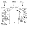
- the drawing figure shows a block diagram of a preferred embodiment of the system according to the invention.
- a central monitoring unit 1 comprises a pattern recognition equipment 2, the input 3 of which is connected to a frequency analyzer 4 having an input 5 connected via a first telecommunication channel 6 to a sampling device 7 provided with a control input 8 and connected to a vibration sensor 9 mounted on a machine (not shown) to be monitored.
- An output 10 of the pattern recognition equipment 2 serves to signal when the frequency spectra obtained from the frequency analyzer 4 comprises patterns representing deviations from a normal operational condition of the machine.
- the output 10 is connected to a control device 11 having an output 12 connected via a second telecommunication channel 13 to the control input 8 of the sampling device 7.
- Measurement information from the vibration sensor 9 will be transmitted in response to control information transmitted from the control device 11, and a terminal equipment 14 is arranged so as to establish periodically a two-way telecommunication connection 15 including said first and second telecommunication channels 6 and 13.
- the telecommunication connection 15 is a part of the worldwide public telephone net-work and comprises a relay station in the form of a geostationary setellite.
- the terminal equipment 14 consists of a modem and is provided with an automatic dialling input 16 connected to a second output of the control device 11.
- the terminal equipment 14 is connected to a corresponding terminal equipment 17 connected to the sampling device 7 and consisting of a modem having auto-reply facilities. Consequently, the monitored machine may belong to a plant which is remotely located (e.g. an oil field), movable (e.g. a ship) and possibly fully automatic (hydroelectric power station).
- the costs of the components of the inventive system can be kept low as regards the components assembled locally at the plant including the machine to be monitored. It is reasonable to assume that the plant is connected to the public telephone net-work in such a way that the terminal equipment 17 is operative at regular time intervals while being controlled by the control device 11 via the terminal equipment 14 in the central monitoring unit 1.
- the terminal equipment 17 is connected to the sampling device 7 via a communication equipment 18 built around a microprocessor provided with a RAM for programs and data and arranged to be charged with programs via a serial port.
- the sampling device 7 comprises a charge amplifier 19 and an A/D converter 20 serving to connect the vibration sensor 9 to the communication equipment 18.
- the latter is arranged to adjust the gain of the charge amplifier 19 via the control input 8 of the sampling means 7, and additionally to control the A/D converter 20.
- the vibration sensor may be supplemented by several vibration sensors each being connected via an associated charge amplifier to a separate analog input of the A/D converter 20 addressed from the communication equipment 18 while being controlled by a program stored in its RAM and obtained from a communication equipment 21 arranged in the central monitoring unit 1 and likewise including a microprocessor.
- This program generates a time series which is stored in the RAM of the communication equipment 18 and is transmitted after completed sampling to the communication equipment21 via the telecommunication connection 15. The transmission of the time series may be repeated in case of detected faults, e.g. by using - check sums.
- the communication equipment 18 may also receive test programs from the communication equipment 21 for checking the operation of e.g. the charge amplifier 19 and the vibration sensor 9. Before the measuring signal is digitized, it is filtered in an antialiasing filter, i.a. a low pass filter having a steeply declining response characteristic in the high frequency region.
- the upper limit frequency can be set from the control monitoring unit 1, depending on the frequency range being currently examined.
- the microprocessor is provided with programs for further processing of the received time series, i.a. by correcting the measuring values in view of the adjusted gain of the charge amplifier 19, and for conveying the results to the frequency analyzer 4.
- the latter includes a FFT (Fast Fourier Transform) frequency analyzer 22 having an output connected to a microprocessor 23 provided with a program for processing frequency spectra obtained from a frequency analyzer 22 and forming a table containing levels and frequencies forfu rther processing in the pattern recognition equipment 2.
- FFT Fast Fourier Transform
- the pattern recognition equipment 2 comprises a computer provided with the recognition program SIMCA mentioned above.
- this program has been adjusted for the processing of frequency spectra of machine vibrations.
- a reference class of frequency spectra is generated and is later compared with each subsequent frequency spectrum. Under normal conditions, it is not necessary to interpret the frequency spectra.
- the program calculates for every new frequency spectrum the probability that this spectrum belongs to a class different from the reference class. Should this probability be high, the deviated components in the frequency spectrum can be shown and a diagnosis of the operating condition be made. The result can be presented by means of a printer 24 connected to the pattern recognition equipment 2.
Landscapes
- Physics & Mathematics (AREA)
- General Physics & Mathematics (AREA)
- Measurement Of Mechanical Vibrations Or Ultrasonic Waves (AREA)
- Selective Calling Equipment (AREA)
- Testing And Monitoring For Control Systems (AREA)
- Testing Of Devices, Machine Parts, Or Other Structures Thereof (AREA)
Abstract
Claims (5)
Priority Applications (1)
| Application Number | Priority Date | Filing Date | Title |
|---|---|---|---|
| AT84902732T ATE38443T1 (de) | 1983-07-01 | 1984-06-29 | System fuer operationssteuerung einer vorrichtung. |
Applications Claiming Priority (2)
| Application Number | Priority Date | Filing Date | Title |
|---|---|---|---|
| SE8303785 | 1983-07-01 | ||
| SE8303785A SE8303785L (sv) | 1983-07-01 | 1983-07-01 | System for driftkontroll av en maskin |
Publications (2)
| Publication Number | Publication Date |
|---|---|
| EP0148256A1 EP0148256A1 (fr) | 1985-07-17 |
| EP0148256B1 true EP0148256B1 (fr) | 1988-11-02 |
Family
ID=20351855
Family Applications (1)
| Application Number | Title | Priority Date | Filing Date |
|---|---|---|---|
| EP84902732A Expired EP0148256B1 (fr) | 1983-07-01 | 1984-06-29 | Systeme de controle operationnel d'une machine |
Country Status (7)
| Country | Link |
|---|---|
| US (1) | US4559828A (fr) |
| EP (1) | EP0148256B1 (fr) |
| JP (1) | JPS60501775A (fr) |
| AU (1) | AU562333B2 (fr) |
| DE (1) | DE3475015D1 (fr) |
| SE (1) | SE8303785L (fr) |
| WO (1) | WO1985000455A1 (fr) |
Families Citing this family (56)
| Publication number | Priority date | Publication date | Assignee | Title |
|---|---|---|---|---|
| FR2605170A1 (fr) * | 1986-10-09 | 1988-04-15 | Letailleur Bernard | Procede et installation de surveillance de l'evolution de l'usure de machines |
| US5040734A (en) * | 1987-09-22 | 1991-08-20 | The British Petroleum Company P.L.C. | Method for determining physical properties |
| SE8800102D0 (sv) * | 1988-01-13 | 1988-01-13 | Lennart Hedlund | Metod och apparatur for detektering av maskiners transportanordningars och liknande anordningars drifttillstand |
| SE460315B (sv) * | 1988-10-13 | 1989-09-25 | Ludwik Jan Liszka | Saett att fortloepande oevervaka drifttillstaandet hos en maskin |
| NL8802754A (nl) * | 1988-11-09 | 1990-06-01 | Allied Breweries Nederland B V | Bewakingssysteem. |
| US4956999A (en) * | 1988-11-30 | 1990-09-18 | Gp Taurio, Inc. | Methods and apparatus for monitoring structural members subject to transient loads |
| US4901575A (en) * | 1988-11-30 | 1990-02-20 | Gp Taurio, Inc. | Methods and apparatus for monitoring structural members subject to transient loads |
| US4977395A (en) * | 1989-01-31 | 1990-12-11 | The United States Of America As Represented By The Administrator Of The National Aeronautics And Space Administration | Vibration analyzer |
| JPH02225966A (ja) * | 1989-02-27 | 1990-09-07 | Toshiba Corp | 冷却装置の消音装置 |
| US5255565A (en) * | 1991-11-12 | 1993-10-26 | Vibra-Metrics, Inc. | Method and apparatus for monitoring multiple points on a vibrating structure |
| GB2285700B (en) * | 1994-01-12 | 1998-06-24 | Drallim Ind | Monitoring apparatus and method |
| US5471880A (en) * | 1994-04-28 | 1995-12-05 | Electric Power Research Institute | Method and apparatus for isolating and identifying periodic Doppler signals in a turbine |
| JP3179969B2 (ja) * | 1994-07-28 | 2001-06-25 | 松下電器産業株式会社 | 振動解析方法 |
| US5602757A (en) * | 1994-10-20 | 1997-02-11 | Ingersoll-Rand Company | Vibration monitoring system |
| US5610339A (en) * | 1994-10-20 | 1997-03-11 | Ingersoll-Rand Company | Method for collecting machine vibration data |
| US5519756A (en) * | 1994-12-15 | 1996-05-21 | The Brian Company | Local alarm system tamper protection device |
| CA2166162A1 (fr) * | 1994-12-29 | 1996-06-30 | John M. Loeffler | Capteur de vibration pour la transmission d'un vehicule |
| US5893892A (en) * | 1994-12-29 | 1999-04-13 | Dana Corporation | Vibration sensing and diagnostic system for vehicle drive train components |
| US5602749A (en) * | 1995-01-12 | 1997-02-11 | Mtc | Method of data compression and apparatus for its use in monitoring machinery |
| US5764729A (en) * | 1995-02-09 | 1998-06-09 | Brian Company Enterprises | Local alarm system tamper protection device with dual conduits |
| GB2299168A (en) * | 1995-03-22 | 1996-09-25 | British Gas Plc | Vibration monitor |
| US6489884B1 (en) * | 1996-01-30 | 2002-12-03 | Skf Condition Monitoring | Apparatus and method for the remote monitoring of machine condition |
| US5845230A (en) * | 1996-01-30 | 1998-12-01 | Skf Condition Monitoring | Apparatus and method for the remote monitoring of machine condition |
| SE510771C2 (sv) * | 1996-07-05 | 1999-06-21 | Spm Instr Ab | Förfarande för utvärdering av konditionen för en maskin jämte analysapparat samt anordning för samverkan med analysapparaten |
| US20050049801A1 (en) * | 1996-07-05 | 2005-03-03 | Stefan Lindberg | Analysis system |
| US6301514B1 (en) | 1996-08-23 | 2001-10-09 | Csi Technology, Inc. | Method and apparatus for configuring and synchronizing a wireless machine monitoring and communication system |
| US5907491A (en) * | 1996-08-23 | 1999-05-25 | Csi Technology, Inc. | Wireless machine monitoring and communication system |
| US5992237A (en) * | 1997-07-22 | 1999-11-30 | Skf Condition Monitoring, Inc. | Digital vibration coupling stud |
| DE69809751T2 (de) * | 1997-07-22 | 2003-07-17 | Skf Condition Monitoring, Inc. | Schwingungsüberwachungssystem |
| US6255962B1 (en) | 1998-05-15 | 2001-07-03 | System Excelerator, Inc. | Method and apparatus for low power, micro-electronic mechanical sensing and processing |
| GB2349020A (en) * | 1999-04-17 | 2000-10-18 | Interface Inf Syst Ltd | Monitoring condition of a machine |
| GB2354825A (en) * | 1999-07-30 | 2001-04-04 | Eric Atherton | Plant condition monitoring using vibrational measurements |
| EP1102185A3 (fr) * | 1999-11-16 | 2003-05-28 | General Electric Company | Système et méthode d'entretien d'équipement électrique |
| ATE248412T1 (de) * | 1999-12-23 | 2003-09-15 | Abb Ab | Verfahren und vorrichtung zur überwachung des betriebszustandes einer einzelnen maschine |
| US6392584B1 (en) * | 2000-01-04 | 2002-05-21 | Richard Eklund | System and method for detecting and warning of potential failure of rotating and vibrating machines |
| US6567709B1 (en) * | 2000-02-04 | 2003-05-20 | Rem Technology | Integrated monitoring, diagnostics, shut-down and control system |
| US7013287B1 (en) * | 2000-02-22 | 2006-03-14 | Voith Sulzer Paper Technology N. America, Inc. | Stock preparation monitoring system and method of same |
| JP2001320349A (ja) * | 2000-05-08 | 2001-11-16 | Mitsubishi Heavy Ind Ltd | 分散通信装置 |
| IT1318802B1 (it) * | 2000-08-31 | 2003-09-10 | Nuovo Pignone Spa | Sistema di diagnosi remota dello stato di usura delle valvole diaspirazione e mandata di compressori alternativi. |
| US6466134B1 (en) * | 2000-11-20 | 2002-10-15 | Trimble Navigation Limited | Cordless machine operation detector |
| WO2003062768A1 (fr) | 2002-01-18 | 2003-07-31 | Spm Instrument Ab | Systeme d'analyse pour analyser l'etat d'une machine |
| GB0411447D0 (en) * | 2004-05-21 | 2004-06-23 | Navitas Uk Ltd | Valve monitoring system |
| US20060167638A1 (en) * | 2004-11-04 | 2006-07-27 | Murphy Jonathan D M | Data collector with wireless server connection |
| US7253020B2 (en) * | 2005-01-04 | 2007-08-07 | Omnivision Technologies, Inc | Deuterium alloy process for image sensors |
| US7725274B2 (en) | 2006-05-05 | 2010-05-25 | Csi Technology, Inc. | Method and apparatus for identifying a region of interest of transient vibration data requiring analysis |
| US7421349B1 (en) * | 2006-05-15 | 2008-09-02 | United States Of America As Represented By The Secretary Of The Navy | Bearing fault signature detection |
| US20090031019A1 (en) * | 2007-07-27 | 2009-01-29 | Burr Michael J | Technique for Graphically Displaying Application Processing Time Distributions in Real-Time |
| US20100169817A1 (en) * | 2008-12-31 | 2010-07-01 | Roy Want | Method and apparatus for context enhanced wireless discovery |
| WO2010095457A1 (fr) * | 2009-02-20 | 2010-08-26 | 日本電気株式会社 | Système, procédé et programme de prétraitement d'analyse |
| US8297123B2 (en) * | 2009-07-30 | 2012-10-30 | General Electric Company | Detection of anomalous movement in a reciprocating device |
| CN102707680B (zh) * | 2012-05-22 | 2014-04-02 | 李朝晖 | 水电机组全方位一体化协同在线监测系统及使用方法 |
| US9302058B2 (en) * | 2013-03-15 | 2016-04-05 | Curlin Medical Inc. | Infusion tubing tracing system using vibration generator and vibration sensor |
| CN104089791A (zh) * | 2014-07-28 | 2014-10-08 | 郑州航空工业管理学院 | 基于振动的改进损伤定位和损伤程度识别方法 |
| US10908014B2 (en) | 2014-08-21 | 2021-02-02 | Baker Hughes, A Ge Company, Llc | Detecting rotor anomalies during transient speed operations |
| WO2020075296A1 (fr) * | 2018-10-12 | 2020-04-16 | 三菱電機株式会社 | Dispositif de surveillance d'état |
| CN109522263B (zh) * | 2018-11-16 | 2021-10-29 | 郑州云海信息技术有限公司 | 一种i2c链路监控系统 |
Family Cites Families (12)
| Publication number | Priority date | Publication date | Assignee | Title |
|---|---|---|---|---|
| US3156910A (en) * | 1959-08-10 | 1964-11-10 | James S Tarbutton | Telemetering system |
| GB1402986A (en) * | 1971-05-13 | 1975-08-13 | Kent Meters Ltd | Interrogation of remote stations |
| US3758758A (en) * | 1972-03-10 | 1973-09-11 | United Aircraft Corp | Weighting rotational statistical vibration analysis employing sidebands and/or |
| US3936822A (en) * | 1974-06-14 | 1976-02-03 | Hirschberg Kenneth A | Method and apparatus for detecting weapon fire |
| US4006461A (en) * | 1975-02-03 | 1977-02-01 | Tull Aviation Corporation | System for transmitting operating condition data from a passive station to a central station |
| US4060716A (en) * | 1975-05-19 | 1977-11-29 | Rockwell International Corporation | Method and apparatus for automatic abnormal events monitor in operating plants |
| US4001798A (en) * | 1975-09-18 | 1977-01-04 | Rockwell International Corporation | Self-contained sensor |
| US4167730A (en) * | 1977-04-18 | 1979-09-11 | General Electric Company | Compression of data on status of remote equipment |
| US4184205A (en) * | 1977-11-25 | 1980-01-15 | Ird Mechanalysis, Inc. | Data acquisition system |
| US4270174A (en) * | 1979-02-05 | 1981-05-26 | Sun Electric Corporation | Remote site engine test techniques |
| AU526370B2 (en) * | 1981-01-29 | 1983-01-06 | Hitachi Limited | Diagnosing vibration of rotary machine |
| US4399440A (en) * | 1981-02-17 | 1983-08-16 | Sparton Corporation | Addressable transducer with a variable frequency oscillation for monitoring a physical quantity |
-
1983
- 1983-07-01 SE SE8303785A patent/SE8303785L/xx not_active Application Discontinuation
-
1984
- 1984-06-26 US US06/624,593 patent/US4559828A/en not_active Expired - Fee Related
- 1984-06-29 WO PCT/SE1984/000249 patent/WO1985000455A1/fr not_active Ceased
- 1984-06-29 DE DE8484902732T patent/DE3475015D1/de not_active Expired
- 1984-06-29 EP EP84902732A patent/EP0148256B1/fr not_active Expired
- 1984-06-29 JP JP84502677A patent/JPS60501775A/ja active Pending
- 1984-06-29 AU AU31038/84A patent/AU562333B2/en not_active Ceased
Non-Patent Citations (3)
| Title |
|---|
| "Objektive akustische Güteprüfung durch Mustererkennung und Signalanalyse"; Dissertation H. E. Meier, Technische Hochschule, Karlsruhe, 1980 * |
| D. Barschdorff et al., "Geräuschanalyse zur Schadenfrüherkennung an stationären Turbomaschinen als Problem der Mustererkennung", Technisches Messen atm 1977, Vol. 5, pp. 181-188 * |
| H. Gudat "Methoden und industrielle Anwendungen der akustischen Mustererkennung", Technisches Messen atm 1977, Vol. 5, pp. 175-180; Vol. 6, pp. 209-216 * |
Also Published As
| Publication number | Publication date |
|---|---|
| AU3103884A (en) | 1985-02-07 |
| WO1985000455A1 (fr) | 1985-01-31 |
| EP0148256A1 (fr) | 1985-07-17 |
| JPS60501775A (ja) | 1985-10-17 |
| US4559828A (en) | 1985-12-24 |
| SE8303785L (sv) | 1985-01-02 |
| AU562333B2 (en) | 1987-06-04 |
| DE3475015D1 (en) | 1988-12-08 |
| SE8303785D0 (sv) | 1983-07-01 |
Similar Documents
| Publication | Publication Date | Title |
|---|---|---|
| US4559828A (en) | System for operational monitoring of a machine | |
| EP0438443B1 (fr) | Procede de surveillance d'une machine | |
| EP1250577B1 (fr) | Systeme reparti d'analyse d'onde de contraintes | |
| US5995910A (en) | Method and system for synthesizing vibration data | |
| US4425798A (en) | Apparatus for diagnosing abnormalities in rotating machines | |
| US5965819A (en) | Parallel processing in a vibration analyzer | |
| US5396180A (en) | System for monitoring gas insulated substations | |
| US20100280772A1 (en) | Method for detection and automatic identification of damage to rolling bearings | |
| JPH0681573A (ja) | 無線伝送手段を備えたボーリングロッド用動力測定アセンブリ | |
| GB2277151A (en) | Machine monitoring using neural network | |
| JP2001108518A (ja) | 異常検知方法および装置 | |
| WO1997010580A1 (fr) | Emetteur de transmission radio d'informations de position d'arbre | |
| CA1218744A (fr) | Systeme de controle des parametres de fonctionnement d'une machine | |
| CN112491486B (zh) | 一种无线通讯设备的干扰检测系统 | |
| JPH08307962A (ja) | 遠隔監視装置 | |
| JP3748638B2 (ja) | 移動体通信を用いる検査システム | |
| JPH08289376A (ja) | 機器運転データ測定監視システム | |
| CN118981668B (zh) | 一种便携式旋转类设备故障诊断仪及诊断方法 | |
| KR102770837B1 (ko) | 철도 시설물 데이터 수집 방법 | |
| CN117119503A (zh) | 基于5g工业互联网的智慧矿山数据采集方法 | |
| Di Giovambattista et al. | Amplitude response of a telemetered seismic system from seismometers to digital acquisition system | |
| CN120446311A (zh) | 一种基于声敏传感器的混凝土泵送状态监测装置及方法 | |
| CN121388491A (zh) | 一种电站设备参数自适应测试方法 | |
| Di Giovambattista et al. | Amplitude response of a telemetered seismic system | |
| EA051489B1 (ru) | Система диагностики технического состояния силового трансформатора |
Legal Events
| Date | Code | Title | Description |
|---|---|---|---|
| PUAI | Public reference made under article 153(3) epc to a published international application that has entered the european phase |
Free format text: ORIGINAL CODE: 0009012 |
|
| 17P | Request for examination filed |
Effective date: 19850401 |
|
| AK | Designated contracting states |
Designated state(s): AT BE CH DE FR GB LI LU NL SE |
|
| 17Q | First examination report despatched |
Effective date: 19860704 |
|
| GRAA | (expected) grant |
Free format text: ORIGINAL CODE: 0009210 |
|
| AK | Designated contracting states |
Kind code of ref document: B1 Designated state(s): AT BE CH DE FR GB LI LU NL SE |
|
| REF | Corresponds to: |
Ref document number: 38443 Country of ref document: AT Date of ref document: 19881115 Kind code of ref document: T |
|
| REF | Corresponds to: |
Ref document number: 3475015 Country of ref document: DE Date of ref document: 19881208 |
|
| ET | Fr: translation filed | ||
| PGFP | Annual fee paid to national office [announced via postgrant information from national office to epo] |
Ref country code: LU Payment date: 19890621 Year of fee payment: 6 |
|
| PG25 | Lapsed in a contracting state [announced via postgrant information from national office to epo] |
Ref country code: LU Free format text: LAPSE BECAUSE OF NON-PAYMENT OF DUE FEES Effective date: 19890630 |
|
| PLBI | Opposition filed |
Free format text: ORIGINAL CODE: 0009260 |
|
| 26 | Opposition filed |
Opponent name: CARL SCHENCK AG Effective date: 19890726 |
|
| NLR1 | Nl: opposition has been filed with the epo |
Opponent name: CARL SCHENCK AG |
|
| PGFP | Annual fee paid to national office [announced via postgrant information from national office to epo] |
Ref country code: CH Payment date: 19900622 Year of fee payment: 7 |
|
| PGFP | Annual fee paid to national office [announced via postgrant information from national office to epo] |
Ref country code: AT Payment date: 19900625 Year of fee payment: 7 |
|
| PGFP | Annual fee paid to national office [announced via postgrant information from national office to epo] |
Ref country code: BE Payment date: 19900627 Year of fee payment: 7 |
|
| PGFP | Annual fee paid to national office [announced via postgrant information from national office to epo] |
Ref country code: NL Payment date: 19900630 Year of fee payment: 7 |
|
| PGFP | Annual fee paid to national office [announced via postgrant information from national office to epo] |
Ref country code: SE Payment date: 19910612 Year of fee payment: 8 |
|
| PGFP | Annual fee paid to national office [announced via postgrant information from national office to epo] |
Ref country code: FR Payment date: 19910621 Year of fee payment: 8 |
|
| PGFP | Annual fee paid to national office [announced via postgrant information from national office to epo] |
Ref country code: GB Payment date: 19910624 Year of fee payment: 8 |
|
| PG25 | Lapsed in a contracting state [announced via postgrant information from national office to epo] |
Ref country code: AT Effective date: 19910629 |
|
| PG25 | Lapsed in a contracting state [announced via postgrant information from national office to epo] |
Ref country code: LI Free format text: LAPSE BECAUSE OF NON-PAYMENT OF DUE FEES Effective date: 19910630 Ref country code: CH Free format text: LAPSE BECAUSE OF NON-PAYMENT OF DUE FEES Effective date: 19910630 Ref country code: BE Effective date: 19910630 |
|
| PGFP | Annual fee paid to national office [announced via postgrant information from national office to epo] |
Ref country code: DE Payment date: 19910801 Year of fee payment: 8 |
|
| BERE | Be: lapsed |
Owner name: LISZKA LUDWIK JAN Effective date: 19910630 |
|
| PG25 | Lapsed in a contracting state [announced via postgrant information from national office to epo] |
Ref country code: NL Effective date: 19920101 |
|
| NLV4 | Nl: lapsed or anulled due to non-payment of the annual fee | ||
| REG | Reference to a national code |
Ref country code: CH Ref legal event code: PL |
|
| PG25 | Lapsed in a contracting state [announced via postgrant information from national office to epo] |
Ref country code: GB Effective date: 19920629 |
|
| PG25 | Lapsed in a contracting state [announced via postgrant information from national office to epo] |
Ref country code: SE Effective date: 19920630 |
|
| RDAG | Patent revoked |
Free format text: ORIGINAL CODE: 0009271 |
|
| STAA | Information on the status of an ep patent application or granted ep patent |
Free format text: STATUS: PATENT REVOKED |
|
| GBPC | Gb: european patent ceased through non-payment of renewal fee |
Effective date: 19920629 |
|
| 27W | Patent revoked |
Effective date: 19921212 |
|
| REG | Reference to a national code |
Ref country code: FR Ref legal event code: ST |
|
| EUG | Se: european patent has lapsed |
Ref document number: 84902732.1 Effective date: 19930109 |