EP2876366A1 - Lampe avec élément de serrage - Google Patents
Lampe avec élément de serrage Download PDFInfo
- Publication number
- EP2876366A1 EP2876366A1 EP13005488.5A EP13005488A EP2876366A1 EP 2876366 A1 EP2876366 A1 EP 2876366A1 EP 13005488 A EP13005488 A EP 13005488A EP 2876366 A1 EP2876366 A1 EP 2876366A1
- Authority
- EP
- European Patent Office
- Prior art keywords
- groove
- housing element
- luminaire
- clamping element
- housing
- Prior art date
- Legal status (The legal status is an assumption and is not a legal conclusion. Google has not performed a legal analysis and makes no representation as to the accuracy of the status listed.)
- Granted
Links
Images


Classifications
-
- F—MECHANICAL ENGINEERING; LIGHTING; HEATING; WEAPONS; BLASTING
- F21—LIGHTING
- F21V—FUNCTIONAL FEATURES OR DETAILS OF LIGHTING DEVICES OR SYSTEMS THEREOF; STRUCTURAL COMBINATIONS OF LIGHTING DEVICES WITH OTHER ARTICLES, NOT OTHERWISE PROVIDED FOR
- F21V17/00—Fastening of component parts of lighting devices, e.g. shades, globes, refractors, reflectors, filters, screens, grids or protective cages
- F21V17/10—Fastening of component parts of lighting devices, e.g. shades, globes, refractors, reflectors, filters, screens, grids or protective cages characterised by specific fastening means or way of fastening
- F21V17/107—Fastening of component parts of lighting devices, e.g. shades, globes, refractors, reflectors, filters, screens, grids or protective cages characterised by specific fastening means or way of fastening using hinge joints
-
- F—MECHANICAL ENGINEERING; LIGHTING; HEATING; WEAPONS; BLASTING
- F21—LIGHTING
- F21V—FUNCTIONAL FEATURES OR DETAILS OF LIGHTING DEVICES OR SYSTEMS THEREOF; STRUCTURAL COMBINATIONS OF LIGHTING DEVICES WITH OTHER ARTICLES, NOT OTHERWISE PROVIDED FOR
- F21V15/00—Protecting lighting devices from damage
- F21V15/01—Housings, e.g. material or assembling of housing parts
-
- F—MECHANICAL ENGINEERING; LIGHTING; HEATING; WEAPONS; BLASTING
- F21—LIGHTING
- F21V—FUNCTIONAL FEATURES OR DETAILS OF LIGHTING DEVICES OR SYSTEMS THEREOF; STRUCTURAL COMBINATIONS OF LIGHTING DEVICES WITH OTHER ARTICLES, NOT OTHERWISE PROVIDED FOR
- F21V17/00—Fastening of component parts of lighting devices, e.g. shades, globes, refractors, reflectors, filters, screens, grids or protective cages
- F21V17/10—Fastening of component parts of lighting devices, e.g. shades, globes, refractors, reflectors, filters, screens, grids or protective cages characterised by specific fastening means or way of fastening
- F21V17/104—Fastening of component parts of lighting devices, e.g. shades, globes, refractors, reflectors, filters, screens, grids or protective cages characterised by specific fastening means or way of fastening using feather joints, e.g. tongues and grooves, with or without friction
-
- F—MECHANICAL ENGINEERING; LIGHTING; HEATING; WEAPONS; BLASTING
- F21—LIGHTING
- F21V—FUNCTIONAL FEATURES OR DETAILS OF LIGHTING DEVICES OR SYSTEMS THEREOF; STRUCTURAL COMBINATIONS OF LIGHTING DEVICES WITH OTHER ARTICLES, NOT OTHERWISE PROVIDED FOR
- F21V17/00—Fastening of component parts of lighting devices, e.g. shades, globes, refractors, reflectors, filters, screens, grids or protective cages
- F21V17/10—Fastening of component parts of lighting devices, e.g. shades, globes, refractors, reflectors, filters, screens, grids or protective cages characterised by specific fastening means or way of fastening
- F21V17/12—Fastening of component parts of lighting devices, e.g. shades, globes, refractors, reflectors, filters, screens, grids or protective cages characterised by specific fastening means or way of fastening by screwing
-
- F—MECHANICAL ENGINEERING; LIGHTING; HEATING; WEAPONS; BLASTING
- F21—LIGHTING
- F21V—FUNCTIONAL FEATURES OR DETAILS OF LIGHTING DEVICES OR SYSTEMS THEREOF; STRUCTURAL COMBINATIONS OF LIGHTING DEVICES WITH OTHER ARTICLES, NOT OTHERWISE PROVIDED FOR
- F21V17/00—Fastening of component parts of lighting devices, e.g. shades, globes, refractors, reflectors, filters, screens, grids or protective cages
- F21V17/10—Fastening of component parts of lighting devices, e.g. shades, globes, refractors, reflectors, filters, screens, grids or protective cages characterised by specific fastening means or way of fastening
- F21V17/16—Fastening of component parts of lighting devices, e.g. shades, globes, refractors, reflectors, filters, screens, grids or protective cages characterised by specific fastening means or way of fastening by deformation of parts; Snap action mounting
- F21V17/164—Fastening of component parts of lighting devices, e.g. shades, globes, refractors, reflectors, filters, screens, grids or protective cages characterised by specific fastening means or way of fastening by deformation of parts; Snap action mounting the parts being subjected to bending, e.g. snap joints
-
- F—MECHANICAL ENGINEERING; LIGHTING; HEATING; WEAPONS; BLASTING
- F21—LIGHTING
- F21V—FUNCTIONAL FEATURES OR DETAILS OF LIGHTING DEVICES OR SYSTEMS THEREOF; STRUCTURAL COMBINATIONS OF LIGHTING DEVICES WITH OTHER ARTICLES, NOT OTHERWISE PROVIDED FOR
- F21V31/00—Gas-tight or water-tight arrangements
- F21V31/005—Sealing arrangements therefor
Definitions
- a generic luminaire comprises a first housing element which comprises at least one groove, a second housing element and a clamping element. Furthermore, the clamping element of a generic luminaire comprises a first connection region and a second connection region, wherein the first connection region cooperates with the groove and the second connection region is connected in the mounted state to the second housing element, so that the second housing element by the clamping element against the first housing element is tense.
- a lamp of the type mentioned is from the EP 0 539 621 B1 known.
- a clamping element is used to clamp a support plate against a side part.
- Designed as an angle rail piece clamping element is inserted with one end in a rectangular groove on the side part and bolted to the support plate.
- the disadvantage of the EP 0 539 621 B1 known lamp is that the clamping element can not reliably clamp the side part and the support plate against each other. Tolerances in the production lead to a tilting of the clamping element in the groove, as a result of which the groove and the clamping element can be easily damaged, and the support plate and side part are not reliably braced against one another. In the compensation you need a plurality of clamping elements, which unnecessarily complicates the assembly.
- a rotatable mounting means not only a pure rotation of the clamping element, but also includes an additional or simultaneous translation of the clamping element.
- the first housing element may be a housing frame or part of a housing frame, but also a carrier or mounting plate and a simple mounting element.
- the second housing element may be a lid-like component, but also a carrier or mounting plate, a fastening element or another component of the lamp to be clamped against the first housing element.
- At least one further component of the luminaire is arranged between the first housing element and the second housing element. This may, for example, hold a cover glass.
- the groove can be arranged on any surface of the first housing element.
- the first housing member may include a plurality of grooves of different configurations arranged on the same or different surfaces.
- the invention offers the advantages that first housing element and second housing element can be reliably braced against each other.
- the clamping element can also be designed such that it bears against the second housing element between the groove and the connection with the second housing element, so that the force transmitted to the clamping element is transmitted to the second housing element reinforced by a lever action.
- a luminaire according to the invention can be made very modular. For example, when using a plurality of grooves on the first housing element, different second housing elements can be inserted into the luminaire.
- At least one positive-locking element is formed in the first connecting region, wherein the groove and the positive-locking element are designed such that the positive-locking element can rotate in the groove.
- the clamping element is rigid, so that the clamping effect occurs through the connection of the second connection region with the second housing element.
- the clamping element is made of metal as a casting or a profile strip.
- the clamping element is held captive in at least one rotational position in the groove.
- the assembly is considerably simplified, since the clamping element does not have to be held in the meantime. It is also conceivable to design the first connection region and the groove such that the clamping element is held captive in the groove in all rotational positions.
- the clamping element in the groove is rotatable from a mounting position to the position in the mounted state can be transferred. This simplifies the installation of the luminaire.
- the clamping element is held captive in the mounting position. This allows the clamping element to be first arranged in the mounting position and then the second housing element can be inserted into the luminaire.
- the angle of rotation between the position in the assembled state and the mounting position is at least 60 °. In the mounting position, this results in a large space for mounting other components of the lamp. Preferably, the angle of rotation is at least 80 °.
- the first housing element surrounds the second housing element like a frame and comprises a groove on at least two opposite inner sides.
- the grooves each cooperate with at least one clamping element, wherein in the mounting position of the clear distance between two opposing clamping elements is at least as large as the extension of the second housing element.
- the clamping elements allow a straight insertion of the second housing element in the mounting position. This simplifies a mechanical installation of the lamp.
- a single-part or multi-part first housing element surrounds the second housing element at least in sections.
- the first housing element may be formed as a surrounding frame into which a second housing element designed as a cover is inserted.
- the clamping element is displaceable in the groove along the longitudinal extension of the groove. Since the position of the clamping element along the groove can be adapted to different second housing elements, the luminaire according to the invention can be used more versatile.
- the groove is interrupted by at least one insertion region, wherein the clamping element can be inserted into the groove over the insertion region in the direction of the longitudinal extension of the groove.
- a Einsetz Scheme allows easy insertion of the clamping element in the groove.
- at least a part of the wall of the groove can be interrupted in the insertion region, so that the clamping element can be introduced into the insertion region in a direction parallel to the surface of the first housing element.
- the groove may be widened in the insertion area.
- the groove and the first connecting region in such a way that the clamping element can be converted into a rotational position in which it can be removed from the groove via a pivoting movement in a plane perpendicular to the longitudinal extension of the groove or in the opposite direction insert the groove.
- the groove and the clamping element act together in the manner of a hinge joint.
- This embodiment represents a particularly easy to manufacture type of rotatable mounting according to the invention.
- the groove comprises a first undercut which engages around an end of the first connection region. This results in a large contact area between the groove and the first connection region and falling out of the clamp element in a direction perpendicular to the end of the first connection region is prevented. Due to the extent of embracing the rotational angle range of the clamping element can be limited. By suitable design of the first undercut, the captive mounting of the clamping element in the groove can be easily realized.
- the groove comprises a second undercut, wherein the second undercut overlaps the first connection region.
- the second undercut may surround a part of the first connection element like a tub.
- the first connection region is substantially hook-shaped.
- the bent end cooperates with the first undercut and the adjoining curved portion engages the second undercut.
- a chop-shaped clamping element can be easily produced from a profile strip or as a cast part.
- the second connection region is screwed to the second housing element.
- This type of detachable connection makes it easy to assemble and disassemble the luminaire.
- screws can be screwed through the clamping element into threaded bores which are formed on the second housing element.
- threaded bolts are formed on the second housing element, which penetrate the clamping element and are screwed onto the nut for fastening.
- other releasable connection methods are conceivable.
- At least one slot is formed in the second connecting region, which extends in the mounted state perpendicular to the longitudinal extension of the groove.
- a fastening element such as a threaded bolt formed on the second housing element.
- a nut can be used to convert the clamping element when tightening the nut in the mounted state.
- the threaded bolt moves by the rotational movement of the clamping element in the slot.
- edges of the second housing element are rounded at least in the region of the clamping elements. Rounded edges increase the contact surface with the clamping element and prevent a clamping element resting against the second housing element from being damaged by punctual loading.
- the clamping element comprises a contact region, which is arranged between the first connection region and the second connection region, wherein, at least in the mounted state, the contact region is in contact with an edge of the second housing element.
- a force is transmitted to the clamping element on the side facing away from the second housing element by a fastening element.
- the rotatable bearing serves as the pivot point of the clamping element, whereby due to the lever effect, a larger force in the contact region is transmitted to the second housing element.
- the contact region may at least partially coincide with the second connection region.
- the edge of the second housing element is rounded in the region of the contact region.
- the clamping member is rotated during assembly until it rests with the contact portion at the rounded edge of the second housing member.
- the force subsequently applied to the second connection region is transmitted to the second housing element in the contact region in an amplified manner.
- the luminaire comprises a seal, which is arranged between the first housing element and the second housing element, and bears against the first housing element and the second housing element.
- the first housing element is clamped by the clamping element in the mounted state against the second housing element, so that the second housing element is pressed against the seal and the seal seals the first housing element against the second housing element.
- the clamping member is rotated during assembly until it rests with the contact portion at the rounded edge of the second housing member.
- the force subsequently applied to the second connection area is transmitted to the second housing element in the contact area in an increased manner, as a result of which the second housing element is pressed against the seal and compresses it.
- the second housing element moves toward the seal and the clamping element is rotated accordingly. Clamping element and rounded edge are formed so that they remain in contact during the connection process.
- At least one further component of the luminaire for example a cover glass, is arranged between the first housing element and the second housing element and bears against the seal. It is also conceivable that at least one further component of the luminaire is arranged between the seal and the first housing element and / or between the seal and the second housing element, so that the seal bears only indirectly on at least one of the two housing elements.
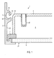
- first housing member 2 which has a groove 3, a second housing member 4 and a clamping member, not shown 5.
- the first housing member 2 is formed as a one-piece housing frame which defines on its underside a light exit opening 21 and on its inside 22nd has a circumferential groove 3.
- a cover glass 6 is arranged on the housing frame 2.
- a seal 7 abuts against the housing frame 2, the second housing element 4 and the cover glass 6.
- the second housing element 4 is formed as a one-piece cover and has on its upper side rounded edges 41 and threaded holes 42 for receiving screws 9.
- the cover glass 6 is integrally formed.
- the seal 7 rotates integrally the entire lower edge of the housing frame 2. Between cover 4 and cover glass 6 there is a gap 8, in the other, not shown components of the lamp 1, such as the light source or the power supply can be arranged.
- the groove 3 upwards a first undercut 31 and a second undercut 32 down.
- the first undercut 31 is circular segment-shaped and surrounds the circular segment-shaped end 54 of the first connecting portion 51, so that the clamping element 5 is rotatably mounted.
- the second undercut 32 is formed like a trough and engages over the first connection region 51, wherein the first connection region 51 rests against the second undercut 32 in the mounted state.
- the Fig. 2 shows an embodiment of a clamping element 5 of a lamp according to the invention.
- the clamping element 5 has a first connection region 51, a second connection region 52 and a contact region 53.
- the clamping element 5 is made of a metal profile.
- the first connection region 51 is hook-shaped, wherein the end of the first connection region 51 is formed in a circular segment, in order to engage with the first undercut 31 of the groove 3 cooperate.
- the hook-shaped design results in a substantially U-shaped intermediate region 55, in which the wall 33 of the first undercut 31 engages and thus limits the rotational angle range upwards.
- a falling out of the clamping element 5 is prevented from the groove 3 perpendicular to the surface of the housing inner wall 22.
- the trough-like, second undercut 32 additionally prevents falling of the clamping element 5 parallel to the housing inner wall 22, so that the clamping element 5 is held captive in all rotational positions in the groove 3.
- the second connection region 32 has two slots 56 in the illustrated embodiment.
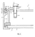
- the Fig. 3 shows the clamping element 5 of Fig. 2 arranged in the groove 3 according to the embodiment of Fig. 1 ,
- a screw 9 penetrates the clamping element 5 at a slot 56 and is inserted into the threaded bore 42 on the cover 4.
- the clamping element 5 rests with the contact region 53 against the rounded edge 41 of the cover 4.
- the clamping element 5 acts like a lever, wherein the force applied by the screw 9 from above on the clamping element 5 force in the contact area 53 reinforced on the cover 4, is transmitted down.
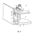
- Fig. 4 illustrated embodiment corresponds to the embodiment of FIG. 3
- threaded bolts 43 are formed, which penetrate the clamping element 5 and are screwed onto the nut 10 for fastening.
- the Fig. 5 shows the embodiment of the Fig. 3 in the assembled state.
- the screw 9 has moved in the slot 56. Due to the rounded edge 41 and the rounded contact area 53, the second housing element 4 and the clamping element 5 are in contact with each other during the clamping process via a large contact surface.
- the first connecting portion 51 is in contact with the second undercut 32 so that the clamping member 5 can not be further rotated. This limitation prevents damage to the individual components.
- the lid 4 is pressed against the seal 7, whereby the lid 4 is sealed against the housing frame 2.
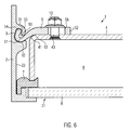
- Fig. 6 shows the embodiment of the Fig. 4 in the assembled state.
- Fig. 7 shows the insertion portion 34 of the groove 3 of a lamp 1 according to the invention in the illustrated embodiment, the first undercut 31 in the insertion region 34 of Groove 3 interrupted. Furthermore, the groove 3 is formed so that the clamping element 5 of Fig. 2 along the longitudinal extension of the groove 3 in the groove 3 is displaceable. For inserting the clamping element 5, this is first introduced from above into the insertion region 34 and then inserted along the longitudinal extension of the groove 3 from the insertion region 34 into the groove 3.
- Fig. 8 shows a further embodiment of a lamp 1 according to the invention, which is characterized by the execution of the groove 3 and the clamping member 5 of the in the FIG. 1 illustrated embodiment differs.
- the clamping element 5 is in the mounting position.
- the angle of rotation between the dashed shown, mounted position and the mounting position corresponds to approximately 90 °.
- the end 54 of the first connecting portion 51 has rotated in the first undercut 31 and completed a translation.
- a clamping element 5 is also mounted in the groove 3 in the mounting position.
- the clear distance of the two clamping elements 5 is greater than the extension of the lid 4,
- the cover 4 can be used straight from above into the housing frame 2, after the clamping elements 5 were arranged in the groove 3 in the mounting position.
- the clamping element 5 is inserted later.
Landscapes
- Engineering & Computer Science (AREA)
- General Engineering & Computer Science (AREA)
- Arrangement Of Elements, Cooling, Sealing, Or The Like Of Lighting Devices (AREA)
- Clamps And Clips (AREA)
- Non-Portable Lighting Devices Or Systems Thereof (AREA)
Priority Applications (2)
| Application Number | Priority Date | Filing Date | Title |
|---|---|---|---|
| EP13005488.5A EP2876366B1 (fr) | 2013-11-25 | 2013-11-25 | Lampe avec élément de serrage |
| US14/525,908 US9739456B2 (en) | 2013-11-25 | 2014-10-28 | Luminaire having a clamping member |
Applications Claiming Priority (1)
| Application Number | Priority Date | Filing Date | Title |
|---|---|---|---|
| EP13005488.5A EP2876366B1 (fr) | 2013-11-25 | 2013-11-25 | Lampe avec élément de serrage |
Publications (2)
| Publication Number | Publication Date |
|---|---|
| EP2876366A1 true EP2876366A1 (fr) | 2015-05-27 |
| EP2876366B1 EP2876366B1 (fr) | 2016-10-26 |
Family
ID=49726416
Family Applications (1)
| Application Number | Title | Priority Date | Filing Date |
|---|---|---|---|
| EP13005488.5A Active EP2876366B1 (fr) | 2013-11-25 | 2013-11-25 | Lampe avec élément de serrage |
Country Status (2)
| Country | Link |
|---|---|
| US (1) | US9739456B2 (fr) |
| EP (1) | EP2876366B1 (fr) |
Families Citing this family (4)
| Publication number | Priority date | Publication date | Assignee | Title |
|---|---|---|---|---|
| US9746159B1 (en) * | 2015-03-03 | 2017-08-29 | Ecosense Lighting Inc. | Lighting system having a sealing system |
| US10638815B2 (en) * | 2018-06-25 | 2020-05-05 | Taiwan Oasis Technology Co., Ltd. | Buckle joint structure |
| CN110906215B (zh) * | 2019-10-21 | 2025-12-16 | 晨辉光宝科技股份有限公司 | 防止塌陷的灯具 |
| US11536425B1 (en) | 2021-06-28 | 2022-12-27 | Ch Lighting Technology Co., Ltd. | Lamp and lamp mounting structure |
Citations (7)
| Publication number | Priority date | Publication date | Assignee | Title |
|---|---|---|---|---|
| BE750444A (fr) * | 1970-05-14 | 1970-10-16 | Financ Applic Elec | Boitier avec couvercle pourvu d'un dispositif de fermeture, |
| EP0148334A2 (fr) * | 1983-12-23 | 1985-07-17 | Siemens Aktiengesellschaft | Dispositif pour la fixation d'accessoires sur la paroi d'une armature lumineuse |
| FR2638508A1 (fr) * | 1988-11-02 | 1990-05-04 | Sammode Sa | Articulation-verrou pour enveloppe de luminaire en plusieurs parties |
| EP0539621B1 (fr) | 1991-10-31 | 1995-02-01 | Siemens Aktiengesellschaft | Système d'éclairage modulaire de locaux |
| DE20321366U1 (de) * | 2003-10-31 | 2006-12-21 | NORKA Norddeutsche Kunststoff- und Elektro-Gesellschaft Stäcker mbH & Co. KG | Leuchtengehäuse, insbesondere für eine Langfeldleuchte |
| WO2012007413A1 (fr) * | 2010-07-14 | 2012-01-19 | Osram Gesellschaft mit beschränkter Haftung | Élément de fixation, module d'éclairage et dispositif d'éclairage |
| WO2012139311A1 (fr) * | 2011-04-11 | 2012-10-18 | 浙江捷莱照明有限公司 | Structure de scellement hermétique de lampe en forme de barre |
Family Cites Families (3)
| Publication number | Priority date | Publication date | Assignee | Title |
|---|---|---|---|---|
| DE3900226A1 (de) * | 1989-01-05 | 1990-07-12 | Siemens Ag | Lichtfluter |
| US6511212B2 (en) * | 2001-05-08 | 2003-01-28 | Hubbell Incorporated | Luminaire latch |
| US7249870B1 (en) * | 2004-01-06 | 2007-07-31 | Electrix, Inc. | Light fixture having a housing with a channel for receiving a front element |
-
2013
- 2013-11-25 EP EP13005488.5A patent/EP2876366B1/fr active Active
-
2014
- 2014-10-28 US US14/525,908 patent/US9739456B2/en active Active
Patent Citations (7)
| Publication number | Priority date | Publication date | Assignee | Title |
|---|---|---|---|---|
| BE750444A (fr) * | 1970-05-14 | 1970-10-16 | Financ Applic Elec | Boitier avec couvercle pourvu d'un dispositif de fermeture, |
| EP0148334A2 (fr) * | 1983-12-23 | 1985-07-17 | Siemens Aktiengesellschaft | Dispositif pour la fixation d'accessoires sur la paroi d'une armature lumineuse |
| FR2638508A1 (fr) * | 1988-11-02 | 1990-05-04 | Sammode Sa | Articulation-verrou pour enveloppe de luminaire en plusieurs parties |
| EP0539621B1 (fr) | 1991-10-31 | 1995-02-01 | Siemens Aktiengesellschaft | Système d'éclairage modulaire de locaux |
| DE20321366U1 (de) * | 2003-10-31 | 2006-12-21 | NORKA Norddeutsche Kunststoff- und Elektro-Gesellschaft Stäcker mbH & Co. KG | Leuchtengehäuse, insbesondere für eine Langfeldleuchte |
| WO2012007413A1 (fr) * | 2010-07-14 | 2012-01-19 | Osram Gesellschaft mit beschränkter Haftung | Élément de fixation, module d'éclairage et dispositif d'éclairage |
| WO2012139311A1 (fr) * | 2011-04-11 | 2012-10-18 | 浙江捷莱照明有限公司 | Structure de scellement hermétique de lampe en forme de barre |
Also Published As
| Publication number | Publication date |
|---|---|
| US20150146438A1 (en) | 2015-05-28 |
| EP2876366B1 (fr) | 2016-10-26 |
| US9739456B2 (en) | 2017-08-22 |
Similar Documents
| Publication | Publication Date | Title |
|---|---|---|
| EP3384567B1 (fr) | Châssis pour armoire électrique | |
| EP3504391B1 (fr) | Ensemble charnière pour un boitier d'armoire électrique et un boitier d'armoire électrique correspondant | |
| EP3625860A1 (fr) | Passage de câble | |
| EP3649353B1 (fr) | Système de fixation | |
| EP3613931B1 (fr) | Module de bande destiné au raccordement mobile par charnière autour d'un axe de charnière d'un battant sur un cadre | |
| EP2876366B1 (fr) | Lampe avec élément de serrage | |
| EP2792834B1 (fr) | Système comprenant un profilé de retenue pour un profilé de cadre et protection contre les chutes intégrée dans le cadre | |
| DE202005006528U1 (de) | Befestigungsprofil | |
| EP3130717B1 (fr) | Liaison poteau/verrou | |
| EP2559120A1 (fr) | Partie boîtier pour une armoire de commande | |
| DE202007003675U1 (de) | Vorrichtung zur Befestigung von Beschlagteilen an Hohlprofilen | |
| DE102008052291B4 (de) | Montageschiene | |
| EP3692611B1 (fr) | Dispositif de positionnement d'une piece plat sur un châssis d'armoire électrique et procédé correspondant | |
| AT525006B1 (de) | Montageprofil | |
| EP1602836B1 (fr) | Nervure raidisseuse pour bois massif | |
| AT516721A4 (de) | Geländer und Verfahren zur Herstellung eines Geländers | |
| DE102021201300B3 (de) | Vorrichtung zur Durchführung von Strängen | |
| EP2902563B1 (fr) | Marquise | |
| DE102015006717B3 (de) | Solarmodulhalteanordnung | |
| DE202010001441U1 (de) | Justiersystem für Bauelemente | |
| EP3044534B1 (fr) | Système de montage pour la fixation d'un élément annexe sur un rail en forme de c | |
| AT524668B1 (de) | Montageelement | |
| EP4425002A1 (fr) | Raccord à vis | |
| EP3379013A1 (fr) | Dispositif de guidage réglable pour un élément coulissant | |
| DE102016218256B4 (de) | Dachfenster |
Legal Events
| Date | Code | Title | Description |
|---|---|---|---|
| PUAI | Public reference made under article 153(3) epc to a published international application that has entered the european phase |
Free format text: ORIGINAL CODE: 0009012 |
|
| 17P | Request for examination filed |
Effective date: 20140805 |
|
| AK | Designated contracting states |
Kind code of ref document: A1 Designated state(s): AL AT BE BG CH CY CZ DE DK EE ES FI FR GB GR HR HU IE IS IT LI LT LU LV MC MK MT NL NO PL PT RO RS SE SI SK SM TR |
|
| AX | Request for extension of the european patent |
Extension state: BA ME |
|
| 17Q | First examination report despatched |
Effective date: 20151116 |
|
| GRAP | Despatch of communication of intention to grant a patent |
Free format text: ORIGINAL CODE: EPIDOSNIGR1 |
|
| INTG | Intention to grant announced |
Effective date: 20160519 |
|
| GRAS | Grant fee paid |
Free format text: ORIGINAL CODE: EPIDOSNIGR3 |
|
| GRAA | (expected) grant |
Free format text: ORIGINAL CODE: 0009210 |
|
| AK | Designated contracting states |
Kind code of ref document: B1 Designated state(s): AL AT BE BG CH CY CZ DE DK EE ES FI FR GB GR HR HU IE IS IT LI LT LU LV MC MK MT NL NO PL PT RO RS SE SI SK SM TR |
|
| REG | Reference to a national code |
Ref country code: GB Ref legal event code: FG4D Free format text: NOT ENGLISH |
|
| REG | Reference to a national code |
Ref country code: CH Ref legal event code: EP |
|
| REG | Reference to a national code |
Ref country code: AT Ref legal event code: REF Ref document number: 840287 Country of ref document: AT Kind code of ref document: T Effective date: 20161115 |
|
| REG | Reference to a national code |
Ref country code: IE Ref legal event code: FG4D Free format text: LANGUAGE OF EP DOCUMENT: GERMAN |
|
| REG | Reference to a national code |
Ref country code: FR Ref legal event code: PLFP Year of fee payment: 4 |
|
| REG | Reference to a national code |
Ref country code: DE Ref legal event code: R096 Ref document number: 502013005082 Country of ref document: DE |
|
| REG | Reference to a national code |
Ref country code: LT Ref legal event code: MG4D |
|
| PG25 | Lapsed in a contracting state [announced via postgrant information from national office to epo] |
Ref country code: BE Free format text: LAPSE BECAUSE OF NON-PAYMENT OF DUE FEES Effective date: 20161130 Ref country code: LV Free format text: LAPSE BECAUSE OF FAILURE TO SUBMIT A TRANSLATION OF THE DESCRIPTION OR TO PAY THE FEE WITHIN THE PRESCRIBED TIME-LIMIT Effective date: 20161026 |
|
| REG | Reference to a national code |
Ref country code: NL Ref legal event code: MP Effective date: 20161026 |
|
| PG25 | Lapsed in a contracting state [announced via postgrant information from national office to epo] |
Ref country code: SE Free format text: LAPSE BECAUSE OF FAILURE TO SUBMIT A TRANSLATION OF THE DESCRIPTION OR TO PAY THE FEE WITHIN THE PRESCRIBED TIME-LIMIT Effective date: 20161026 Ref country code: LT Free format text: LAPSE BECAUSE OF FAILURE TO SUBMIT A TRANSLATION OF THE DESCRIPTION OR TO PAY THE FEE WITHIN THE PRESCRIBED TIME-LIMIT Effective date: 20161026 Ref country code: GR Free format text: LAPSE BECAUSE OF FAILURE TO SUBMIT A TRANSLATION OF THE DESCRIPTION OR TO PAY THE FEE WITHIN THE PRESCRIBED TIME-LIMIT Effective date: 20170127 Ref country code: NO Free format text: LAPSE BECAUSE OF FAILURE TO SUBMIT A TRANSLATION OF THE DESCRIPTION OR TO PAY THE FEE WITHIN THE PRESCRIBED TIME-LIMIT Effective date: 20170126 |
|
| PG25 | Lapsed in a contracting state [announced via postgrant information from national office to epo] |
Ref country code: FI Free format text: LAPSE BECAUSE OF FAILURE TO SUBMIT A TRANSLATION OF THE DESCRIPTION OR TO PAY THE FEE WITHIN THE PRESCRIBED TIME-LIMIT Effective date: 20161026 Ref country code: PT Free format text: LAPSE BECAUSE OF FAILURE TO SUBMIT A TRANSLATION OF THE DESCRIPTION OR TO PAY THE FEE WITHIN THE PRESCRIBED TIME-LIMIT Effective date: 20170227 Ref country code: IS Free format text: LAPSE BECAUSE OF FAILURE TO SUBMIT A TRANSLATION OF THE DESCRIPTION OR TO PAY THE FEE WITHIN THE PRESCRIBED TIME-LIMIT Effective date: 20170226 Ref country code: PL Free format text: LAPSE BECAUSE OF FAILURE TO SUBMIT A TRANSLATION OF THE DESCRIPTION OR TO PAY THE FEE WITHIN THE PRESCRIBED TIME-LIMIT Effective date: 20161026 Ref country code: RS Free format text: LAPSE BECAUSE OF FAILURE TO SUBMIT A TRANSLATION OF THE DESCRIPTION OR TO PAY THE FEE WITHIN THE PRESCRIBED TIME-LIMIT Effective date: 20161026 Ref country code: HR Free format text: LAPSE BECAUSE OF FAILURE TO SUBMIT A TRANSLATION OF THE DESCRIPTION OR TO PAY THE FEE WITHIN THE PRESCRIBED TIME-LIMIT Effective date: 20161026 Ref country code: NL Free format text: LAPSE BECAUSE OF FAILURE TO SUBMIT A TRANSLATION OF THE DESCRIPTION OR TO PAY THE FEE WITHIN THE PRESCRIBED TIME-LIMIT Effective date: 20161026 Ref country code: ES Free format text: LAPSE BECAUSE OF FAILURE TO SUBMIT A TRANSLATION OF THE DESCRIPTION OR TO PAY THE FEE WITHIN THE PRESCRIBED TIME-LIMIT Effective date: 20161026 |
|
| REG | Reference to a national code |
Ref country code: CH Ref legal event code: PL |
|
| REG | Reference to a national code |
Ref country code: DE Ref legal event code: R097 Ref document number: 502013005082 Country of ref document: DE |
|
| PG25 | Lapsed in a contracting state [announced via postgrant information from national office to epo] |
Ref country code: RO Free format text: LAPSE BECAUSE OF FAILURE TO SUBMIT A TRANSLATION OF THE DESCRIPTION OR TO PAY THE FEE WITHIN THE PRESCRIBED TIME-LIMIT Effective date: 20161026 Ref country code: DK Free format text: LAPSE BECAUSE OF FAILURE TO SUBMIT A TRANSLATION OF THE DESCRIPTION OR TO PAY THE FEE WITHIN THE PRESCRIBED TIME-LIMIT Effective date: 20161026 Ref country code: CH Free format text: LAPSE BECAUSE OF NON-PAYMENT OF DUE FEES Effective date: 20161130 Ref country code: EE Free format text: LAPSE BECAUSE OF FAILURE TO SUBMIT A TRANSLATION OF THE DESCRIPTION OR TO PAY THE FEE WITHIN THE PRESCRIBED TIME-LIMIT Effective date: 20161026 Ref country code: SK Free format text: LAPSE BECAUSE OF FAILURE TO SUBMIT A TRANSLATION OF THE DESCRIPTION OR TO PAY THE FEE WITHIN THE PRESCRIBED TIME-LIMIT Effective date: 20161026 Ref country code: LI Free format text: LAPSE BECAUSE OF NON-PAYMENT OF DUE FEES Effective date: 20161130 Ref country code: MC Free format text: LAPSE BECAUSE OF FAILURE TO SUBMIT A TRANSLATION OF THE DESCRIPTION OR TO PAY THE FEE WITHIN THE PRESCRIBED TIME-LIMIT Effective date: 20161026 Ref country code: CZ Free format text: LAPSE BECAUSE OF FAILURE TO SUBMIT A TRANSLATION OF THE DESCRIPTION OR TO PAY THE FEE WITHIN THE PRESCRIBED TIME-LIMIT Effective date: 20161026 |
|
| REG | Reference to a national code |
Ref country code: IE Ref legal event code: MM4A |
|
| PG25 | Lapsed in a contracting state [announced via postgrant information from national office to epo] |
Ref country code: BG Free format text: LAPSE BECAUSE OF FAILURE TO SUBMIT A TRANSLATION OF THE DESCRIPTION OR TO PAY THE FEE WITHIN THE PRESCRIBED TIME-LIMIT Effective date: 20170126 Ref country code: SM Free format text: LAPSE BECAUSE OF FAILURE TO SUBMIT A TRANSLATION OF THE DESCRIPTION OR TO PAY THE FEE WITHIN THE PRESCRIBED TIME-LIMIT Effective date: 20161026 |
|
| PLBE | No opposition filed within time limit |
Free format text: ORIGINAL CODE: 0009261 |
|
| STAA | Information on the status of an ep patent application or granted ep patent |
Free format text: STATUS: NO OPPOSITION FILED WITHIN TIME LIMIT |
|
| PG25 | Lapsed in a contracting state [announced via postgrant information from national office to epo] |
Ref country code: LU Free format text: LAPSE BECAUSE OF NON-PAYMENT OF DUE FEES Effective date: 20161130 |
|
| 26N | No opposition filed |
Effective date: 20170727 |
|
| REG | Reference to a national code |
Ref country code: FR Ref legal event code: PLFP Year of fee payment: 5 |
|
| PG25 | Lapsed in a contracting state [announced via postgrant information from national office to epo] |
Ref country code: IE Free format text: LAPSE BECAUSE OF NON-PAYMENT OF DUE FEES Effective date: 20161125 Ref country code: SI Free format text: LAPSE BECAUSE OF FAILURE TO SUBMIT A TRANSLATION OF THE DESCRIPTION OR TO PAY THE FEE WITHIN THE PRESCRIBED TIME-LIMIT Effective date: 20161026 |
|
| REG | Reference to a national code |
Ref country code: BE Ref legal event code: MM Effective date: 20161130 |
|
| PG25 | Lapsed in a contracting state [announced via postgrant information from national office to epo] |
Ref country code: HU Free format text: LAPSE BECAUSE OF FAILURE TO SUBMIT A TRANSLATION OF THE DESCRIPTION OR TO PAY THE FEE WITHIN THE PRESCRIBED TIME-LIMIT; INVALID AB INITIO Effective date: 20131125 |
|
| PG25 | Lapsed in a contracting state [announced via postgrant information from national office to epo] |
Ref country code: MK Free format text: LAPSE BECAUSE OF FAILURE TO SUBMIT A TRANSLATION OF THE DESCRIPTION OR TO PAY THE FEE WITHIN THE PRESCRIBED TIME-LIMIT Effective date: 20161026 Ref country code: CY Free format text: LAPSE BECAUSE OF FAILURE TO SUBMIT A TRANSLATION OF THE DESCRIPTION OR TO PAY THE FEE WITHIN THE PRESCRIBED TIME-LIMIT Effective date: 20161026 |
|
| PG25 | Lapsed in a contracting state [announced via postgrant information from national office to epo] |
Ref country code: MT Free format text: LAPSE BECAUSE OF FAILURE TO SUBMIT A TRANSLATION OF THE DESCRIPTION OR TO PAY THE FEE WITHIN THE PRESCRIBED TIME-LIMIT Effective date: 20161026 |
|
| PG25 | Lapsed in a contracting state [announced via postgrant information from national office to epo] |
Ref country code: TR Free format text: LAPSE BECAUSE OF FAILURE TO SUBMIT A TRANSLATION OF THE DESCRIPTION OR TO PAY THE FEE WITHIN THE PRESCRIBED TIME-LIMIT Effective date: 20161026 |
|
| PG25 | Lapsed in a contracting state [announced via postgrant information from national office to epo] |
Ref country code: AL Free format text: LAPSE BECAUSE OF FAILURE TO SUBMIT A TRANSLATION OF THE DESCRIPTION OR TO PAY THE FEE WITHIN THE PRESCRIBED TIME-LIMIT Effective date: 20161026 |
|
| PGFP | Annual fee paid to national office [announced via postgrant information from national office to epo] |
Ref country code: DE Payment date: 20251128 Year of fee payment: 13 |
|
| PGFP | Annual fee paid to national office [announced via postgrant information from national office to epo] |
Ref country code: GB Payment date: 20251125 Year of fee payment: 13 |
|
| PGFP | Annual fee paid to national office [announced via postgrant information from national office to epo] |
Ref country code: AT Payment date: 20251124 Year of fee payment: 13 |
|
| PGFP | Annual fee paid to national office [announced via postgrant information from national office to epo] |
Ref country code: IT Payment date: 20251127 Year of fee payment: 13 |
|
| PGFP | Annual fee paid to national office [announced via postgrant information from national office to epo] |
Ref country code: FR Payment date: 20251128 Year of fee payment: 13 |
|
| REG | Reference to a national code |
Ref country code: DE Ref legal event code: R082 Ref document number: 502013005082 Country of ref document: DE Representative=s name: HABERMANN INTELLECTUAL PROPERTY PARTNERSCHAFT , DE |