EP0148662B1 - Verfahren und Vorrichtung zum Befüllen von Zweikammeraerosolbehältern - Google Patents
Verfahren und Vorrichtung zum Befüllen von Zweikammeraerosolbehältern Download PDFInfo
- Publication number
- EP0148662B1 EP0148662B1 EP84402411A EP84402411A EP0148662B1 EP 0148662 B1 EP0148662 B1 EP 0148662B1 EP 84402411 A EP84402411 A EP 84402411A EP 84402411 A EP84402411 A EP 84402411A EP 0148662 B1 EP0148662 B1 EP 0148662B1
- Authority
- EP
- European Patent Office
- Prior art keywords
- compartment
- substance
- valve
- receptacle
- metering
- Prior art date
- Legal status (The legal status is an assumption and is not a legal conclusion. Google has not performed a legal analysis and makes no representation as to the accuracy of the status listed.)
- Expired
Links
- 238000000034 method Methods 0.000 title claims abstract description 36
- 239000000443 aerosol Substances 0.000 title claims abstract description 19
- 239000000126 substance Substances 0.000 claims abstract description 54
- 238000005192 partition Methods 0.000 claims abstract description 17
- 239000012530 fluid Substances 0.000 claims description 8
- 238000006073 displacement reaction Methods 0.000 claims description 5
- 239000013013 elastic material Substances 0.000 claims description 4
- 230000005484 gravity Effects 0.000 claims description 2
- 239000003795 chemical substances by application Substances 0.000 claims 1
- 238000007599 discharging Methods 0.000 claims 1
- 239000003380 propellant Substances 0.000 description 17
- 239000007788 liquid Substances 0.000 description 10
- 239000007789 gas Substances 0.000 description 8
- 230000001143 conditioned effect Effects 0.000 description 7
- 238000002788 crimping Methods 0.000 description 5
- 239000000463 material Substances 0.000 description 5
- IJGRMHOSHXDMSA-UHFFFAOYSA-N Atomic nitrogen Chemical compound N#N IJGRMHOSHXDMSA-UHFFFAOYSA-N 0.000 description 2
- 229910052782 aluminium Inorganic materials 0.000 description 2
- XAGFODPZIPBFFR-UHFFFAOYSA-N aluminium Chemical compound [Al] XAGFODPZIPBFFR-UHFFFAOYSA-N 0.000 description 2
- 238000011109 contamination Methods 0.000 description 2
- 238000004320 controlled atmosphere Methods 0.000 description 2
- 230000000694 effects Effects 0.000 description 2
- 238000004806 packaging method and process Methods 0.000 description 2
- 239000003973 paint Substances 0.000 description 2
- 235000011837 pasties Nutrition 0.000 description 2
- RRHGJUQNOFWUDK-UHFFFAOYSA-N Isoprene Chemical compound CC(=C)C=C RRHGJUQNOFWUDK-UHFFFAOYSA-N 0.000 description 1
- 239000000654 additive Substances 0.000 description 1
- 239000000853 adhesive Substances 0.000 description 1
- 230000001070 adhesive effect Effects 0.000 description 1
- 230000004075 alteration Effects 0.000 description 1
- QVGXLLKOCUKJST-UHFFFAOYSA-N atomic oxygen Chemical compound [O] QVGXLLKOCUKJST-UHFFFAOYSA-N 0.000 description 1
- 244000052616 bacterial pathogen Species 0.000 description 1
- 230000004888 barrier function Effects 0.000 description 1
- 238000004140 cleaning Methods 0.000 description 1
- 239000003814 drug Substances 0.000 description 1
- 229920001971 elastomer Polymers 0.000 description 1
- 229920002457 flexible plastic Polymers 0.000 description 1
- 235000013305 food Nutrition 0.000 description 1
- 230000002070 germicidal effect Effects 0.000 description 1
- 239000003292 glue Substances 0.000 description 1
- 238000009434 installation Methods 0.000 description 1
- 229920001684 low density polyethylene Polymers 0.000 description 1
- 239000004702 low-density polyethylene Substances 0.000 description 1
- 229910052751 metal Inorganic materials 0.000 description 1
- 239000002184 metal Substances 0.000 description 1
- 230000000813 microbial effect Effects 0.000 description 1
- 229910052757 nitrogen Inorganic materials 0.000 description 1
- 239000001301 oxygen Substances 0.000 description 1
- 229910052760 oxygen Inorganic materials 0.000 description 1
- 229920003023 plastic Polymers 0.000 description 1
- 239000004033 plastic Substances 0.000 description 1
- 229920001084 poly(chloroprene) Polymers 0.000 description 1
- 229920001195 polyisoprene Polymers 0.000 description 1
- 230000001681 protective effect Effects 0.000 description 1
- 230000005855 radiation Effects 0.000 description 1
- 239000011347 resin Substances 0.000 description 1
- 229920005989 resin Polymers 0.000 description 1
- 238000007789 sealing Methods 0.000 description 1
- 239000007787 solid Substances 0.000 description 1
- 230000001954 sterilising effect Effects 0.000 description 1
- 238000004659 sterilization and disinfection Methods 0.000 description 1
Images
Classifications
-
- B—PERFORMING OPERATIONS; TRANSPORTING
- B65—CONVEYING; PACKING; STORING; HANDLING THIN OR FILAMENTARY MATERIAL
- B65B—MACHINES, APPARATUS OR DEVICES FOR, OR METHODS OF, PACKAGING ARTICLES OR MATERIALS; UNPACKING
- B65B31/00—Packaging articles or materials under special atmospheric or gaseous conditions; Adding propellants to aerosol containers
- B65B31/003—Adding propellants in fluid form to aerosol containers
Definitions
- the movable or deformable partition is constituted by a pocket which is either of flexible plastic material, such as low density polyethylene, or of pure aluminum, coated.
- This pocket has a single opening.
- the diameter of this opening can be substantially equal to that of the opening of the container and in this case, the pocket is intended to be taken in the crimping by which the closing valve is fixed on the container, or the diameter of the 'opening is close to that of the container and, in this case, the pocket is intended to be taken in the crimping of a flange forming a cover and on which the valve is crimped.
- document US-A-4150522 on which the preambles of claims 1 and 13 are based, relates to a method of filling an aerosol container under a cup, in which a bag is positioned inside the container, after which said bag is filled with the product to be packaged and the vacuum is then applied between the container and the bag filled with product, before introducing the propellant.
- the object of the invention is to provide a process for filling such boxes, sheltered from the atmosphere and without alteration of the substance to be packaged, even when fragile, this process being simple to construct and implement, and therefore inexpensive.
- Another object of the invention is to provide an installation for the implementation of such a method.
- the present invention therefore provides a method of filling an aerosol container with valve, comprising two compartments, the first of which is connected to the valve, separated by a flexible or movable partition, and according to which the substance to be packaged is introduced into the first compartment. , this compartment is closed, then a propellant fluid is introduced or produced in the second compartment.
- a propellant fluid is introduced or produced in the second compartment.
- the valve of the box is placed definitively before the introduction of the substance to be packaged. then said substance is introduced into the first compartment by passing it through the valve.
- the material to be packaged is viscous, such as glue or paint, it is better to operate differently, but at a price an additional complication, and the valve is then placed after the introduction of the substance, in order to close the first compartment.
- a vacuum is made in it while taking precautions so that its volume remains at least equal to the volume of substance that it is desired to introduce therein and the substance is introduced into said first compartment without breaking the vacuum.
- a vacuum is made in the second compartment. This modality is more particularly, but not exclusively, suitable for filling a case where the partition separating the two compartments consists of a deformable sheet of metal or plastic.
- the propellant is produced in a staggered manner during the use of the substance, inside a deformable pocket, constituting the second compartment and introduced into the box before it is closed, it is preferable to use a pocket deformable which has been sealed under vacuum, and that this pocket is introduced into the first compartment which is emptied of air before introducing the substance therein.
- the partition separating the two compartments is constituted by a movable piston
- the volume of the latter is reduced by deformation or displacement of the flexible or movable partition, then the substance is introduced into the first compartment by increasing the volume thereof.
- the metering device comprises a metering capacity which can be connected to the first compartment via a distributing valve and according to a simple embodiment which is applicable to substances of low viscosity, the metering capacity is placed at the -above the aerosol can and the substance is passed from the metering capacity into the first compartment by gravity.
- the metering device comprises at least one metering pump.
- the second compartment is emptied and / or filled using a hollow needle of the hypodermic type perforating said plug.
- the present invention also provides a device intended to be implemented according to the method just described.
- It is a device for filling an aerosol container with two compartments separated by a flexible or movable partition comprising means for holding said container in a filling station with the opening of a first compartment of said container facing the top; means for pouring a metered quantity of the substance to be conditioned into said first compartment; means for fixing a discharge valve of said substance on said opening of the first compartment; and means for introducing or producing a propellant fluid in a second compartment of said container (known for example from document US-A-4150522), characterized in that it further comprises means for removing most of the air contained in the first compartment before the introduction of said substance, and means for protecting said substance from contact with air during said introduction and during the fixing of the valve.
- the device comprises a first device comprising a first conduit capable of being connected in leaktight connection with the first compartment, a second conduit connected to a vacuum source, a metering pump capable of delivering the desired quantity of substance and a valve capable of connecting the first conduit, either to the second conduit, or to the outlet of the metering pump; a second device capable of placing and fixing the valve of the container on the body thereof without bringing the interior of the first compartment into contact with the atmosphere; and means for successively bringing the first and second apparatus into contact with an aerosol can body without putting the first compartment thereof in contact with the atmosphere during the corresponding relative movement.
- the device may further comprise a third device capable of delivering a deformable bag intended to constitute the second compartment inside the aerosol can and means capable of putting said aerosol can in contact with said third. switchgear before putting it into contact with said first switchgear.
- the device further comprises a hollow needle of the hypodermic type; means for introducing the end of the needle into the second compartment, and means for connecting the interior of the needle separately to a source of vacuum and to a source of propellant.
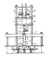
- the reference 1 designates an aerosol container, seen in section, comprising an interior partition 2, made of aluminum, which divides the interior space into two compartments, a first compartment 3 connected to the valve 4, which is of a conventional type, and a second compartment 5, which surrounds the first over almost its entire periphery, and which can be filled with propellant, under pressure or liquid, through a hole 6, provided in the bottom of the container and closed by a plug 7 made of neoprene rubber or similar material.
- the container 1 is placed on a support 8 which is part of the filling device, and it is held at its upper part by a cross member 9, provided with collars or fixing brackets, not shown and integral with the support 8.
- Two vertical slides 10 also integral with the support 8 support the filling means of the first compartment 3.
- These filling means comprise a pre-dosing capacity 11, the volume of which corresponds to that of the compartment 3.
- Several interchangeable pre-dosing capacities, of different volumes, are provided to allow the filling of 1 different containers.
- the predosing capacity is placed above the container 1, and is substantially in the axis thereof.
- a channel 12, provided with a solenoid valve 13 is located at the lower part of the capacity 11.
- the solenoid valve 13 like the other solenoid valves described below, can be replaced by a manual control valve in a simplified version, or by a pneumatic, mechanical or other valve.
- the channel 12 and the solenoid valve 13 are carried by a cross member 15, which is connected to the lower part of the tank 11, and which can slide along the slides 10 between a low position where the seal 14 comes to ensure the connection between the channel 12 and the compartment 3, via the valve 4, and a high position (not shown) where the channel 12 is separated from the container 1.
- a low position where the seal 14 comes to ensure the connection between the channel 12 and the compartment 3, via the valve 4, and a high position (not shown) where the channel 12 is separated from the container 1.
- known means and not shown such that a pusher, keep the valve 4 in the open position, these means allow the valve to close when the cross member 15 deviates from the low position.
- Another crosspiece 16 similar to the crosspiece 15 is connected to the upper part of the capacity 11. It carries two channels 17, 18 connected, the first to a vacuum source, and the second, by means of liquid supply to introduce into compartment 3. These two channels are each provided with a solenoid valve 19, 20, and they open at the top of the capacity 11.
- the support 8 is movable along the slides 10 and, in step b) it rises with the container 1, the cross members 15, 16 being fixed.
- the process is also the same as that which we have just described.
- An advantage of this solution compared to the previous one is that it makes it possible to provide for the conduits supplying the capacity 11; conduits 17 and 18 and possibly additional conduits are rigid, the cross member 16 being linked to the slides 10.
- the cross member 15 can be adjustable in position to adapt to capacities 11 of different height.
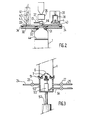
- Figure 2 relates to a variant of the device of Figure 1, this variant corresponding to the filling of the container before the establishment of the valve. Only the upper part of the container 1 is shown, with the neighboring members. Parts similar to those in fig. 1 have the same references.
- a first horizontal plate 30 comprises a window 31 surrounded by a seal 32 which is supported on the upper part of the container 1, around the opening intended to receive the valve 4.
- a second plate 33 is placed above above the first board and can slide on it. Seals 34 are interposed between the two plates.
- the tray 33 carries several devices: a filling device comprises a positive displacement pump 35, which is connected to an orifice 36 which passes through the tray 33, through a three-way valve 37 connected to a vacuum duct 17.
- a device of obturation comprises means 38 of known type for the fitting and crimping of a valve 4.
- This apparatus is surrounded by a sealed bell 39, in which a vacuum can be created, and it is in relation to a window 40 of the tray 33.
- the tray 33 can optionally also carry a third device 41 which consists of a flexible bag dispenser 42 containing a product generating pressurized fluid, in case this technique is used.
- This apparatus makes the pockets 42 pass one by one through an orifice 43 in the plate 33.
- the container 1 is successively brought under the orifice 43 if it is in operation, under the orifice 35 and under the window 40, after which the container can be removed. If the flexible bag technique is not used, the second compartment can receive, at the end of the crimping of the valve, the propellant, after which the filled container is evacuated.
- the apparatus is aligned, for a linear movement of the plates relative to each other.
- the plates can also be circular and move by rotation around a vertical axis.
- piston 44 which separates the two compartments of the container. It is clear that this piston can be replaced by a flexible partition, or be eliminated in the case of the flexible bag technique.
- Figure 3 relates to another variant of the device of Figure 1, this variant corresponding to the filling of the second compartment. Only the lower part of the container 1 is this time shown, with the neighboring members.
- a bell 30 bears on the container 1, and it is pressed against the edge of its bottom with the interposition of a seal 51, by a jack 52.
- another jack 53 carries a plug 7 of elastic material. This plug is kept apart from the hole 6 provided at the bottom of the container, in the position indicated in the figure.
- the jack 53 acts to put the plug in place.
- the bell 50 is connected by two channels 24, 25 each provided with a solenoid valve 26, 27 to a source of vacuum and to a source of propellant. .
- the supply pipe 54 of the jack 53 passes tightly through the wall of the bell 50.
- the invention can find numerous applications for all products which must not be brought into contact with the ambient atmosphere, in particular for the packaging, with a view to consumption or analysis, of various drinks and other food products, as well than in medicine, biology, cosmetology, etc., or for the packaging of products that fear contact with air, such as paints, resins, adhesives, etc.
Landscapes
- Chemical & Material Sciences (AREA)
- Dispersion Chemistry (AREA)
- Engineering & Computer Science (AREA)
- Mechanical Engineering (AREA)
- Vacuum Packaging (AREA)
- Containers And Packaging Bodies Having A Special Means To Remove Contents (AREA)
- Basic Packing Technique (AREA)
- Colloid Chemistry (AREA)
Claims (18)
Priority Applications (1)
| Application Number | Priority Date | Filing Date | Title |
|---|---|---|---|
| AT84402411T ATE34352T1 (de) | 1983-12-01 | 1984-11-26 | Verfahren und vorrichtung zum befuellen von zweikammeraerosolbehaeltern. |
Applications Claiming Priority (2)
| Application Number | Priority Date | Filing Date | Title |
|---|---|---|---|
| FR8319239 | 1983-12-01 | ||
| FR8319239A FR2555965B1 (fr) | 1983-12-01 | 1983-12-01 | Procede de remplissage de boites aerosols a deux compartiments |
Publications (3)
| Publication Number | Publication Date |
|---|---|
| EP0148662A1 EP0148662A1 (de) | 1985-07-17 |
| EP0148662B1 true EP0148662B1 (de) | 1988-05-18 |
| EP0148662B2 EP0148662B2 (de) | 1991-12-04 |
Family
ID=9294759
Family Applications (1)
| Application Number | Title | Priority Date | Filing Date |
|---|---|---|---|
| EP84402411A Expired - Lifetime EP0148662B2 (de) | 1983-12-01 | 1984-11-26 | Verfahren und Vorrichtung zum Befüllen von Zweikammeraerosolbehältern |
Country Status (7)
| Country | Link |
|---|---|
| US (1) | US4589452A (de) |
| EP (1) | EP0148662B2 (de) |
| JP (1) | JPS60158025A (de) |
| AT (1) | ATE34352T1 (de) |
| DE (1) | DE3471285D1 (de) |
| ES (1) | ES8603781A1 (de) |
| FR (1) | FR2555965B1 (de) |
Families Citing this family (17)
| Publication number | Priority date | Publication date | Assignee | Title |
|---|---|---|---|---|
| US4876038A (en) * | 1987-12-10 | 1989-10-24 | Colgate-Palmolive Company | Apparatus for making a post-foaming gel |
| EP0324932B1 (de) * | 1987-12-10 | 1993-09-08 | Colgate-Palmolive Company | Vorrichtung zur Herstellung eines nachschäumenden Gels |
| US4980085A (en) * | 1987-12-10 | 1990-12-25 | Colgate-Palmolive Company | Apparatus for making post-foaming gels and method |
| US5078911A (en) * | 1987-12-10 | 1992-01-07 | Colgate-Palmolive Company | Apparatus for making a post-foaming gel |
| US4915881A (en) * | 1987-12-10 | 1990-04-10 | Colgate-Palmolive Company | Apparatus for making a post foaming gel |
| US5112525A (en) * | 1987-12-10 | 1992-05-12 | Colgate-Palmolive Company | Method for making a post-foaming gel |
| US4857241A (en) * | 1987-12-10 | 1989-08-15 | Colgate-Palmolive Company | Apparatus for making post-foaming gels and method |
| DE3923903A1 (de) * | 1989-07-19 | 1991-01-24 | Hirsch Anton | Verfahren zur befuellung von druckgaspackungen sowie druckgaspackung |
| FI910201A7 (fi) * | 1991-01-15 | 1992-07-16 | Pentti Turunen | System foer anvaendning av aerosoler och aerosolfoerpackningar. |
| JPH0751503Y2 (ja) * | 1991-10-31 | 1995-11-22 | リズム時計工業株式会社 | 噴霧器自動加圧装置 |
| US5462099A (en) * | 1994-01-28 | 1995-10-31 | S. C. Johnson & Son, Inc. | System and method for pressurizing dispensing containers |
| DE59500858D1 (de) * | 1995-05-18 | 1997-11-27 | Rapid Spray Gmbh & Co Kg | Verfahren und Vorrichtung zum Befüllen einer Aerosoldose |
| DE19634101C2 (de) * | 1996-08-23 | 1998-07-02 | Daimler Benz Ag | Lenkungsanlage für ein Kraftfahrzeug mit einer unteren Lenkspindel |
| GB0028692D0 (en) * | 2000-11-24 | 2001-01-10 | Btg Int Ltd | Generation of therapeutic microform |
| US8459311B2 (en) * | 2002-06-17 | 2013-06-11 | Ronald D. Green | Multi-valve delivery system |
| US8844584B1 (en) * | 2010-02-05 | 2014-09-30 | Bissell Homecare, Inc. | Apparatus and method for a pressurized dispenser refill system |
| CN102514763B (zh) * | 2012-01-09 | 2013-06-19 | 扬州美达灌装机械有限公司 | 气雾剂灌装用高效进给机构 |
Family Cites Families (10)
| Publication number | Priority date | Publication date | Assignee | Title |
|---|---|---|---|---|
| FR1451841A (fr) * | 1965-10-26 | 1966-01-07 | Dispositif de remplissage de bombes aérosol et similaires | |
| FR1540379A (fr) | 1967-04-24 | 1968-09-27 | Atad | Conditionneuse de liquides alimentaires ou autres |
| US3748818A (en) * | 1971-08-09 | 1973-07-31 | Kartridg Pak Co | Container filling apparatus |
| JPS5828179B2 (ja) * | 1973-02-20 | 1983-06-14 | アンビロ スプレイ システムズ インコ−ポレ−テツド | アツリヨクヨウキ |
| US4150522A (en) * | 1977-03-07 | 1979-04-24 | Nicholas A. Mardesich | Method for undercap filling of a barrier pack aerosol container |
| US4328843A (en) * | 1978-02-27 | 1982-05-11 | Minoru Fujii | Pressurized dispensers for dispensing products utilizing a pressure transfer fluid |
| IE51803B1 (en) * | 1979-12-19 | 1987-04-01 | Enviro Spray Systems Inc | Self-pressurizing dispensing container |
| JPS5753274U (de) * | 1980-09-12 | 1982-03-27 | ||
| ZA8266B (en) * | 1981-01-13 | 1982-11-24 | Wrightcel Ltd | Liquid filling apparatus |
| JPS5857219B2 (ja) * | 1982-06-29 | 1983-12-19 | アンビロ スプレイ システムズ インコ−ポレ−テツド | 圧力容器中でガス圧を発生する方法 |
-
1983
- 1983-12-01 FR FR8319239A patent/FR2555965B1/fr not_active Expired
-
1984
- 1984-11-26 EP EP84402411A patent/EP0148662B2/de not_active Expired - Lifetime
- 1984-11-26 DE DE8484402411T patent/DE3471285D1/de not_active Expired
- 1984-11-26 AT AT84402411T patent/ATE34352T1/de not_active IP Right Cessation
- 1984-11-30 ES ES538128A patent/ES8603781A1/es not_active Expired
- 1984-11-30 US US06/677,075 patent/US4589452A/en not_active Expired - Fee Related
- 1984-11-30 JP JP59253925A patent/JPS60158025A/ja active Pending
Also Published As
| Publication number | Publication date |
|---|---|
| DE3471285D1 (en) | 1988-06-23 |
| ATE34352T1 (de) | 1988-06-15 |
| FR2555965A1 (fr) | 1985-06-07 |
| ES538128A0 (es) | 1986-01-01 |
| FR2555965B1 (fr) | 1986-10-31 |
| EP0148662A1 (de) | 1985-07-17 |
| JPS60158025A (ja) | 1985-08-19 |
| ES8603781A1 (es) | 1986-01-01 |
| EP0148662B2 (de) | 1991-12-04 |
| US4589452A (en) | 1986-05-20 |
Similar Documents
| Publication | Publication Date | Title |
|---|---|---|
| EP0148662B1 (de) | Verfahren und Vorrichtung zum Befüllen von Zweikammeraerosolbehältern | |
| EP0549049B1 (de) | Abgabevorrichtung für wenigstens ein flüssiges Produkt | |
| US6912828B1 (en) | Packaging method and apparatus | |
| EP2313319B1 (de) | Verfahren zum verpacken eines fluidprodukts in einem spender | |
| EP1877314B1 (de) | Verfahren und vorrichtung zum füllen eines behältnisses mit variablem nutzvolumen | |
| EP1572375B1 (de) | Manuell betätigte dosierpumpe | |
| EP0002987A1 (de) | Verfahren und Maschine zur Herstellung von Getränken in Einzelportionen am Gebrauchsort und bei diesem Verfahren benütztes Produkt | |
| EP2534052B1 (de) | Verfahren und einheit zur sterilen füllung eines finalen grundbehälters mit für den biopharmaziebereich vorgesehenen inhalten | |
| FR2653744A1 (fr) | Procede pour conditionner sous vide des produits notamment cosmetiques et pharmaceutiques a l'interieur de reservoirs deformables obtures par une pompe de distribution sans reprise d'air, dispositif pour le mettre en óoeuvre et distributeurs ainsi obt. | |
| FR2921905A1 (fr) | Recipient de traitement et/ou de controle de produits comprenant une chambre de protection de moyens de traitement et/ou de controle de ces produits, et conteneur comprenant un tel recipient | |
| CH422561A (fr) | Distributeur-doseur | |
| FR2843373A1 (fr) | Dispositif de conditionnement et d'application d'un produit sous forme fluide | |
| CN108928553A (zh) | 具有密闭密封系统的液体物质容器和使用方法 | |
| EP2703091A1 (de) | Sprühfläschchen für Flüssigprodukt | |
| EP0481854A1 (de) | Verfahren zum Vakuumverpacken von flüssigen oder pastösen Produkten in Spender, Vorrichtung dafür und so erhaltene Spender | |
| FR3109070A1 (fr) | Contenant rotatif anaérobie | |
| EP3866747B1 (de) | Verfahren zur herstellung einer vorrichtung zum zeitweiligen verbinden zweier behälter | |
| EP3106408A2 (de) | Starrer behälter für einen flexiblen beutel für die aufnahme einer biopharmazeutischen flüssigkeit und entsprechendes zusammenbauverfahren | |
| US6705062B1 (en) | Machine for filling and sealing containers | |
| EP1432616B1 (de) | Vorrichtung zum folienverschliessen von verpackungen in einer maschine zum konditionieren unter kontrollierter atmosphäre | |
| BE539623A (de) | ||
| JP2023552709A (ja) | 両側が開口しているカートリッジから粘性物質を排出する方法及びこのための内容物排出装置 | |
| EP1022250A1 (de) | Volumetrische Abfüllvorrichtung | |
| EP1412263B1 (de) | Flexible patrone für flüssigkeiten | |
| FR2763561A1 (fr) | Systeme de gonflage sterile pour un sac a paroi souple ferme |
Legal Events
| Date | Code | Title | Description |
|---|---|---|---|
| PUAI | Public reference made under article 153(3) epc to a published international application that has entered the european phase |
Free format text: ORIGINAL CODE: 0009012 |
|
| AK | Designated contracting states |
Designated state(s): AT BE CH DE FR GB IT LI NL SE |
|
| 17P | Request for examination filed |
Effective date: 19851226 |
|
| 17Q | First examination report despatched |
Effective date: 19860922 |
|
| D17Q | First examination report despatched (deleted) | ||
| GRAA | (expected) grant |
Free format text: ORIGINAL CODE: 0009210 |
|
| AK | Designated contracting states |
Kind code of ref document: B1 Designated state(s): AT BE CH DE FR GB IT LI NL SE |
|
| REF | Corresponds to: |
Ref document number: 34352 Country of ref document: AT Date of ref document: 19880615 Kind code of ref document: T |
|
| PG25 | Lapsed in a contracting state [announced via postgrant information from national office to epo] |
Ref country code: SE Effective date: 19880531 |
|
| REF | Corresponds to: |
Ref document number: 3471285 Country of ref document: DE Date of ref document: 19880623 |
|
| GBT | Gb: translation of ep patent filed (gb section 77(6)(a)/1977) | ||
| ITF | It: translation for a ep patent filed | ||
| PLBI | Opposition filed |
Free format text: ORIGINAL CODE: 0009260 |
|
| 26 | Opposition filed |
Opponent name: AEROSOLS INTERNATIONAL Effective date: 19881004 |
|
| NLR1 | Nl: opposition has been filed with the epo |
Opponent name: AEROSOLS INTERNATIONAL |
|
| PLAB | Opposition data, opponent's data or that of the opponent's representative modified |
Free format text: ORIGINAL CODE: 0009299OPPO |
|
| R26 | Opposition filed (corrected) |
Opponent name: AEROSOLS INTERNATIONAL Effective date: 19881004 |
|
| PUAH | Patent maintained in amended form |
Free format text: ORIGINAL CODE: 0009272 |
|
| STAA | Information on the status of an ep patent application or granted ep patent |
Free format text: STATUS: PATENT MAINTAINED AS AMENDED |
|
| 27A | Patent maintained in amended form |
Effective date: 19911204 |
|
| AK | Designated contracting states |
Kind code of ref document: B2 Designated state(s): AT BE CH DE FR GB IT LI NL SE |
|
| REG | Reference to a national code |
Ref country code: CH Ref legal event code: AEN |
|
| NLR2 | Nl: decision of opposition | ||
| GBTA | Gb: translation of amended ep patent filed (gb section 77(6)(b)/1977) | ||
| ITF | It: translation for a ep patent filed | ||
| NLR3 | Nl: receipt of modified translations in the netherlands language after an opposition procedure | ||
| ITTA | It: last paid annual fee | ||
| PGFP | Annual fee paid to national office [announced via postgrant information from national office to epo] |
Ref country code: BE Payment date: 19961114 Year of fee payment: 13 |
|
| PGFP | Annual fee paid to national office [announced via postgrant information from national office to epo] |
Ref country code: DE Payment date: 19961120 Year of fee payment: 13 |
|
| PGFP | Annual fee paid to national office [announced via postgrant information from national office to epo] |
Ref country code: AT Payment date: 19961122 Year of fee payment: 13 |
|
| PGFP | Annual fee paid to national office [announced via postgrant information from national office to epo] |
Ref country code: NL Payment date: 19961128 Year of fee payment: 13 |
|
| PGFP | Annual fee paid to national office [announced via postgrant information from national office to epo] |
Ref country code: CH Payment date: 19971103 Year of fee payment: 14 |
|
| PG25 | Lapsed in a contracting state [announced via postgrant information from national office to epo] |
Ref country code: AT Free format text: LAPSE BECAUSE OF NON-PAYMENT OF DUE FEES Effective date: 19971126 |
|
| PG25 | Lapsed in a contracting state [announced via postgrant information from national office to epo] |
Ref country code: BE Free format text: LAPSE BECAUSE OF NON-PAYMENT OF DUE FEES Effective date: 19971130 |
|
| BERE | Be: lapsed |
Owner name: CLANET FRANK Effective date: 19971130 |
|
| PG25 | Lapsed in a contracting state [announced via postgrant information from national office to epo] |
Ref country code: NL Free format text: LAPSE BECAUSE OF NON-PAYMENT OF DUE FEES Effective date: 19980601 |
|
| PG25 | Lapsed in a contracting state [announced via postgrant information from national office to epo] |
Ref country code: DE Free format text: LAPSE BECAUSE OF NON-PAYMENT OF DUE FEES Effective date: 19980801 |
|
| NLV4 | Nl: lapsed or anulled due to non-payment of the annual fee |
Effective date: 19980601 |
|
| PG25 | Lapsed in a contracting state [announced via postgrant information from national office to epo] |
Ref country code: LI Free format text: LAPSE BECAUSE OF NON-PAYMENT OF DUE FEES Effective date: 19981130 Ref country code: CH Free format text: LAPSE BECAUSE OF NON-PAYMENT OF DUE FEES Effective date: 19981130 |
|
| REG | Reference to a national code |
Ref country code: CH Ref legal event code: PL |
|
| PGFP | Annual fee paid to national office [announced via postgrant information from national office to epo] |
Ref country code: GB Payment date: 19991124 Year of fee payment: 16 |
|
| PGFP | Annual fee paid to national office [announced via postgrant information from national office to epo] |
Ref country code: FR Payment date: 20000928 Year of fee payment: 17 |
|
| PG25 | Lapsed in a contracting state [announced via postgrant information from national office to epo] |
Ref country code: GB Free format text: LAPSE BECAUSE OF NON-PAYMENT OF DUE FEES Effective date: 20001126 |
|
| GBPC | Gb: european patent ceased through non-payment of renewal fee |
Effective date: 20001126 |
|
| PG25 | Lapsed in a contracting state [announced via postgrant information from national office to epo] |
Ref country code: FR Free format text: LAPSE BECAUSE OF NON-PAYMENT OF DUE FEES Effective date: 20020730 |
|
| REG | Reference to a national code |
Ref country code: FR Ref legal event code: ST |
|
| REG | Reference to a national code |
Ref country code: FR Ref legal event code: ST |