EP0149215A2 - Elektronisches Medizinalthermometer - Google Patents
Elektronisches Medizinalthermometer Download PDFInfo
- Publication number
- EP0149215A2 EP0149215A2 EP84116101A EP84116101A EP0149215A2 EP 0149215 A2 EP0149215 A2 EP 0149215A2 EP 84116101 A EP84116101 A EP 84116101A EP 84116101 A EP84116101 A EP 84116101A EP 0149215 A2 EP0149215 A2 EP 0149215A2
- Authority
- EP
- European Patent Office
- Prior art keywords
- oscillation
- thermometric
- temperature
- electronic clinical
- clinical thermometer
- Prior art date
- Legal status (The legal status is an assumption and is not a legal conclusion. Google has not performed a legal analysis and makes no representation as to the accuracy of the status listed.)
- Granted
Links
Images



Classifications
-
- G—PHYSICS
- G01—MEASURING; TESTING
- G01K—MEASURING TEMPERATURE; MEASURING QUANTITY OF HEAT; THERMALLY-SENSITIVE ELEMENTS NOT OTHERWISE PROVIDED FOR
- G01K7/00—Measuring temperature based on the use of electric or magnetic elements directly sensitive to heat ; Power supply therefor, e.g. using thermoelectric elements
- G01K7/16—Measuring temperature based on the use of electric or magnetic elements directly sensitive to heat ; Power supply therefor, e.g. using thermoelectric elements using resistive elements
- G01K7/18—Measuring temperature based on the use of electric or magnetic elements directly sensitive to heat ; Power supply therefor, e.g. using thermoelectric elements using resistive elements the element being a linear resistance, e.g. platinum resistance thermometer
- G01K7/20—Measuring temperature based on the use of electric or magnetic elements directly sensitive to heat ; Power supply therefor, e.g. using thermoelectric elements using resistive elements the element being a linear resistance, e.g. platinum resistance thermometer in a specially-adapted circuit, e.g. bridge circuit
- G01K7/203—Measuring temperature based on the use of electric or magnetic elements directly sensitive to heat ; Power supply therefor, e.g. using thermoelectric elements using resistive elements the element being a linear resistance, e.g. platinum resistance thermometer in a specially-adapted circuit, e.g. bridge circuit in an oscillator circuit
-
- G—PHYSICS
- G01—MEASURING; TESTING
- G01K—MEASURING TEMPERATURE; MEASURING QUANTITY OF HEAT; THERMALLY-SENSITIVE ELEMENTS NOT OTHERWISE PROVIDED FOR
- G01K13/00—Thermometers specially adapted for specific purposes
- G01K13/20—Clinical contact thermometers for use with humans or animals
Definitions
- the present invention relates to an electronic clinical thermometer for detecting temperature using a thermometric oscillator circuit and detecting the oscillation frequency.
- a prior art electronic clinical thermometer in general use is equipped with a sliding switch for controlling the turning on and off of the power source, and the power is .shut off by operating the sliding switch after the detection of temperature .
- operating such a sliding switch is troublesome, and power is often wasted due to forgetting to turn off the power.
- a temperature sensitive resistor is installed in the circuit of a thermometric oscillator whose oscillation frequency varies with temperature.
- the resistance of the resistor is small so that a large current flows through the resistor, consuming large power. Accordingly, the wasted amount of power due to keeping the power in the on-state during the period for which no operation is needed, has been largely responsible for determining the life of the battery.
- the electronic clinical thermometer in general use is mainly used under the emergency condition in which somebody in the family is having a fever. In that condition, there exists a possibility of finding it inoperative at such an emergency because of the dead battery due to forgetting to turn off the switch.
- the power consumption is too large, there exists a large possibility of having a dead battery due to high frequency of its use there.
- thermometer In order to avoid the dead battery situation due to power exhaustion, there has been proposed a thermometer in which a switching transistor for controlling the turning on and off of the power source is installed in the LSI for clinical thermometer, so arranged as to have the power source to be turned off automatically after elapse of a prescribed time (for example, the times for detecting and displaying the temperature) to eliminate the possibility of forgetting to turn off the switch.
- a prescribed time for example, the times for detecting and displaying the temperature
- the switching transistor for controlling the turning on and off of the power source is disadvantageous due to that it occupies a large area on the LSI chip, defeating the attempts to make the small-sized and low-priced LSI.
- the time interval between the taking of temperature in the room and the visit of the nurse for recording the measured temperature may be relatively large.
- An object of the present invention is to provide an electronic clinical thermometer which is capable of reducing the power consumption.
- Another object of the present invention is to provide an electronic clinical thermometer which is capable of extending the life of the battery used.
- Another object of the present invention is to provide an electronic clinical thermometer which is capable of displaying the body temperature over a long period while aiming at a lower consumption of the power.
- an improved electronic clinical thermometer which includes a thermometric oscillator for converting a variation of the resistance-in the temperature sensitive resistor caused by the temperature to a frequency corresponding to the temperature, a thermometric counter for converting the oscillation frequency of the thermometric oscillator to a temperature value, a maximum value memory circuit for detecting the maximum value of the temperature by comparing successively the content of the thermometric counter, a display circuit for digitally displaying the content of the maximum value memory circuit, and means for discontinuing the oscillation of the thermometric oscillator at a prescribed time after detection of the maximum value of the temperature or detection of the maximum temperature value.
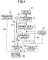
- FIG.l there is shown the circuit constraction of an electronic clinical thermometer embodying the present invention.
- the electronic clinical thermometer in the above includes a thermometric oscillator 10 whose oscillation frequency varies in response to the temperature, a thermometric counter 12 for counting the oscillation frequency of the thermometric oscillator 10 and converting it to the temperature, a maximum value memory circuit 14 for memorizing the maximum temperature value, a comparison circuit 16 for comparing the value from the thermometric counter 12 and the value in the maximum value memory circuit 14 and when the value from the thermometric counter 12 is the larger, the value of the thermometric counter is latched to the maximum value memory circuit 14 as a new maximum value, a display circuit 18 for displaying the value of the maximum value memory circuit 14, and a reference oscillator 20 for outputting the reference clock.
- thermometer includes a clock counter 22 for counting the oscillation frequency of the reference oscillator 20 and for outputting an overflow signal to cause to discontinue the oscillation of the thermomet-ric oscillator 10 after a prescribed time, and a controlling circuit 2 4 for controlling the comparison circuit 16 to output a reset signal to the clock counter 22 in case the maximum value is not detected.
- thermometric oscillator 10- a gate 26 which is controlled by the controlling circuit 24 is arranged between the thermometric oscillator 10- and the thermometric counter 12, and a preset register 28 is connected to the thermometric counter 12.
- thermometric oscillator 10 is constructed, as shown in Fig.2, from a temperature sensitive resistor 30 comprising a linear thermistor whose resistance varies in proportion to the temperature, a capacitor 32, an inverter 34, and a NAND gate 36.
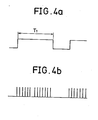
- thermometric oscillator 10 When a signal from the clock counter 22 is inputted to the NAND gate 36 for a fixed time interval Tl, as shown in Fig.4a, the thermometric oscillator 10 begins to oscillate to produce an output pulse S2 at the leading edge of the measurement command pulse Sl, as shown in Fig.4b, and discontinues the oscillation of the output pulse S2 at the trailing edge of the measurement command pulse Sl. Since the frequency of the output pulse S2 of the thermometric osicllator 10 is proportional to the temperature, calibration is made beforehand so as to accommodate the number of output pulses S2 corresponding to the temperature within the interval Tl of the measurement command pulse. By making arrangement in this way, it becomes possible to ' convert the count of the output pulses S2 to the temperature by the use of the thermometric counter 12.
- thermometric counter 12 and the clock counter 22 are reset by the controlling signal from the controlling circuit 24.
- the thermometric counter 12 presets the initial value from the preset register 28, in accordance with the first controlling signal 40 from the controlling circuit 24 created by the output of the reference oscillator (step 102).
- the gate 26 is opened by the second controlling signal 42 from the controlling circuit 24, to allow the thermometric counter 12 to count for a time t the oscillation frequency which is linear relative to the temperature from the thermometric oscillator 10 (step 104).
- the comparison circuit 16 compares, by the third controlling signal 44 from the controlling circuit 24, the content of the thermometric counter 12 and the content of the maximum value memory circuit 14 (step 106). If the result of the comparison shows that the content of the thermometric counter 12 is -larger than the content of the maximum value memory circuit 14, the comparison circuit 16 resets, by the reset signal 46, the clock counter 22 which has been counting the oscillation frequency of the reference oscillator 20 (step 108). With a latch signal 48, the comparison circuit 16 latches the content of the thermometric counter 12 to the maximum value memory circuit 14 as a new maximum value (step 110).
- the display circuit 18 displays digitally the content of the maximum value memory circuit 14 as a temperature value (step 112). If, in step 106, the content of the thermometric counter 12 becomes smaller than the content of the maximum value memory circuit 14, the comparison circuit 16 creates neither a latch signal 48 for latching the content of the thermometric counter 12 to themaximum value memory circuit 14 nor a reset signal 46 for resetting the clock counter 22. If such periods continue, the content of the clock counter 22 continues to be counted up without being reset (step 114). In step 116, when an overflow takes place after a prescribed time, oscillation of the thermometric oscillator 10 is discontinued by the overflow signl 50 from the time counter 22, interrupting the current flowing to the temperature sensitive resistor 30 (step 118).
- thermometric oscillation step 120.
- step 116 if no overflow occurs after a prescribed time, it proceeds to step 112 to digitally display the maximum value, and returns from step 112 to step 102 to preset the thermometric counter 12.
- thermometric oscillation at a prescribed time after the turn-on of the power source.
- the second embodiment differs from the first embodiment, though basically the same, in that it is constructed to begin the counting of the oscillation frequency of the reference oscillator from the moment of turning the power source on, and to discontinue the operation of the thermometric oscillator 10 by causing an overflow without failure after prescribed time.
- thermometric oscillator 10 it is possible to discontinue the oscillation of the thermometric oscillator 10 after elapse of a prescribed time corresponding to the time interval between the beginning of temperature detection and the reading-out of the temperature, achieving a reduction in the power consumption as in the first embodiment.
- thermometric oscillator circuit with thermistor was used in the foregoing embodiments, the present invention is not limited to the use of this circuit, and it may be replaced by any other oscillator circuit as long as the oscillation frequency varies with temperature and it permits the control of on and off of the oscillation.
- the clock generating circuit too need not be limited to the CR oscillator, and, like in the above, any other oscillator circuit with on-off control of oscillation may be utilized as may be found convenient.
Landscapes
- Physics & Mathematics (AREA)
- General Physics & Mathematics (AREA)
- Electric Clocks (AREA)
Applications Claiming Priority (4)
| Application Number | Priority Date | Filing Date | Title |
|---|---|---|---|
| JP58239800A JPS60131431A (ja) | 1983-12-21 | 1983-12-21 | 電子体温計 |
| JP239800/83 | 1983-12-21 | ||
| JP58248984A JPS60142225A (ja) | 1983-12-28 | 1983-12-28 | 電子体温計 |
| JP248984/83 | 1983-12-28 |
Publications (3)
| Publication Number | Publication Date |
|---|---|
| EP0149215A2 true EP0149215A2 (de) | 1985-07-24 |
| EP0149215A3 EP0149215A3 (en) | 1986-05-14 |
| EP0149215B1 EP0149215B1 (de) | 1989-05-31 |
Family
ID=26534427
Family Applications (1)
| Application Number | Title | Priority Date | Filing Date |
|---|---|---|---|
| EP84116101A Expired EP0149215B1 (de) | 1983-12-21 | 1984-12-21 | Elektronisches Medizinalthermometer |
Country Status (2)
| Country | Link |
|---|---|
| EP (1) | EP0149215B1 (de) |
| DE (1) | DE3478498D1 (de) |
Cited By (2)
| Publication number | Priority date | Publication date | Assignee | Title |
|---|---|---|---|---|
| EP1262755A1 (de) | 2001-05-31 | 2002-12-04 | STMicroelectronics, Inc. | Temperaturfühlschaltung sowie zugehöriges Kalibrierungsverfahren |
| WO2013060630A1 (de) * | 2011-10-24 | 2013-05-02 | Continental Automotive Gmbh | Verfahren und vorrichtung zur ermittlung der temperatur eines kraftstoffeinspritzventils und verfahren zur regelung der temperatur eines kraftstoffeinspritzventils |
Family Cites Families (4)
| Publication number | Priority date | Publication date | Assignee | Title |
|---|---|---|---|---|
| AU488012B2 (en) * | 1976-06-21 | 1977-11-10 | American Medical Electronics Corporation | Automatic on-off electronic switch |
| JPS5477082U (de) * | 1977-11-11 | 1979-06-01 | ||
| DE2848112A1 (de) * | 1978-11-06 | 1980-05-08 | Rowenta Werke Gmbh | Elektronisches fieberthermometer |
| CH637474A5 (fr) * | 1979-06-07 | 1983-07-29 | Bioself Int Inc | Thermometre electronique. |
-
1984
- 1984-12-21 DE DE8484116101T patent/DE3478498D1/de not_active Expired
- 1984-12-21 EP EP84116101A patent/EP0149215B1/de not_active Expired
Cited By (3)
| Publication number | Priority date | Publication date | Assignee | Title |
|---|---|---|---|---|
| EP1262755A1 (de) | 2001-05-31 | 2002-12-04 | STMicroelectronics, Inc. | Temperaturfühlschaltung sowie zugehöriges Kalibrierungsverfahren |
| US6695475B2 (en) | 2001-05-31 | 2004-02-24 | Stmicroelectronics, Inc. | Temperature sensing circuit and method |
| WO2013060630A1 (de) * | 2011-10-24 | 2013-05-02 | Continental Automotive Gmbh | Verfahren und vorrichtung zur ermittlung der temperatur eines kraftstoffeinspritzventils und verfahren zur regelung der temperatur eines kraftstoffeinspritzventils |
Also Published As
| Publication number | Publication date |
|---|---|
| EP0149215B1 (de) | 1989-05-31 |
| DE3478498D1 (en) | 1989-07-06 |
| EP0149215A3 (en) | 1986-05-14 |
Similar Documents
| Publication | Publication Date | Title |
|---|---|---|
| US4658407A (en) | Electronic clinical thermometer with power shut-off at maximum temperature | |
| EP1262755B1 (de) | Temperaturfühlschaltung sowie zugehöriges Kalibrierungsverfahren | |
| US7250825B2 (en) | Method and apparatus for calibration of a low frequency oscillator in a processor based system | |
| US4551031A (en) | Electronic clinical thermometer | |
| US4068526A (en) | Electronic thermometer | |
| US10361685B2 (en) | Semiconductor device | |
| US5943206A (en) | Chip temperature protection using delay lines | |
| US6421626B1 (en) | Low voltage/low power temperature sensor | |
| EP1843139B1 (de) | Programmierbarer Timer mit extrem niedriger Leistung und Schaltungen zur Erkennung niedriger Spannungen | |
| EP0149215A2 (de) | Elektronisches Medizinalthermometer | |
| US8120379B2 (en) | Operating characteristic measurement device and methods thereof | |
| US5140132A (en) | Method of and apparatus for controlling fixing device in electrophotographic recording system | |
| JPH0778941A (ja) | 半導体集積回路における過熱保護回路 | |
| JP2692649B2 (ja) | 測定装置およびロジックアナライザ | |
| US6415657B1 (en) | Switch monitoring system | |
| JP3194696B2 (ja) | 温度表示機能付き液体容器 | |
| JPH05326845A (ja) | 半導体集積回路装置 | |
| CN121858350A (zh) | 基于温度补偿的多级阈值看门狗电路及其控制方法、芯片装置 | |
| JPH0261697B2 (de) | ||
| JPS5850060A (ja) | 電子式卓上計算機 | |
| JPS6195254A (ja) | 集積回路装置 | |
| JPS61145423A (ja) | 電子体温計 | |
| JPS60205326A (ja) | 電子温度計 | |
| JPH05334461A (ja) | 1チップマイクロコンピュータ | |
| JPH03165617A (ja) | 初期時クロック発生回路 |
Legal Events
| Date | Code | Title | Description |
|---|---|---|---|
| PUAI | Public reference made under article 153(3) epc to a published international application that has entered the european phase |
Free format text: ORIGINAL CODE: 0009012 |
|
| 17P | Request for examination filed |
Effective date: 19841221 |
|
| AK | Designated contracting states |
Designated state(s): DE FR GB IT |
|
| PUAL | Search report despatched |
Free format text: ORIGINAL CODE: 0009013 |
|
| AK | Designated contracting states |
Kind code of ref document: A3 Designated state(s): DE FR GB IT |
|
| 17Q | First examination report despatched |
Effective date: 19871217 |
|
| GRAA | (expected) grant |
Free format text: ORIGINAL CODE: 0009210 |
|
| AK | Designated contracting states |
Kind code of ref document: B1 Designated state(s): DE FR GB IT |
|
| REF | Corresponds to: |
Ref document number: 3478498 Country of ref document: DE Date of ref document: 19890706 |
|
| ET | Fr: translation filed | ||
| ITF | It: translation for a ep patent filed | ||
| PLBE | No opposition filed within time limit |
Free format text: ORIGINAL CODE: 0009261 |
|
| STAA | Information on the status of an ep patent application or granted ep patent |
Free format text: STATUS: NO OPPOSITION FILED WITHIN TIME LIMIT |
|
| 26N | No opposition filed | ||
| ITTA | It: last paid annual fee | ||
| PGFP | Annual fee paid to national office [announced via postgrant information from national office to epo] |
Ref country code: FR Payment date: 19931209 Year of fee payment: 10 |
|
| PGFP | Annual fee paid to national office [announced via postgrant information from national office to epo] |
Ref country code: GB Payment date: 19931213 Year of fee payment: 10 |
|
| PGFP | Annual fee paid to national office [announced via postgrant information from national office to epo] |
Ref country code: DE Payment date: 19931227 Year of fee payment: 10 |
|
| PG25 | Lapsed in a contracting state [announced via postgrant information from national office to epo] |
Ref country code: GB Effective date: 19941221 |
|
| GBPC | Gb: european patent ceased through non-payment of renewal fee |
Effective date: 19941221 |
|
| PG25 | Lapsed in a contracting state [announced via postgrant information from national office to epo] |
Ref country code: FR Effective date: 19950831 |
|
| PG25 | Lapsed in a contracting state [announced via postgrant information from national office to epo] |
Ref country code: DE Effective date: 19950901 |
|
| REG | Reference to a national code |
Ref country code: FR Ref legal event code: ST |