EP0149384A1 - Rohre mit geschweisstem Boden, insbesondere zum Herstellen eines Hochdruckgasdämpfers - Google Patents
Rohre mit geschweisstem Boden, insbesondere zum Herstellen eines Hochdruckgasdämpfers Download PDFInfo
- Publication number
- EP0149384A1 EP0149384A1 EP84402561A EP84402561A EP0149384A1 EP 0149384 A1 EP0149384 A1 EP 0149384A1 EP 84402561 A EP84402561 A EP 84402561A EP 84402561 A EP84402561 A EP 84402561A EP 0149384 A1 EP0149384 A1 EP 0149384A1
- Authority
- EP
- European Patent Office
- Prior art keywords
- tube
- end piece
- diameter
- folded
- welded
- Prior art date
- Legal status (The legal status is an assumption and is not a legal conclusion. Google has not performed a legal analysis and makes no representation as to the accuracy of the status listed.)
- Granted
Links
- 239000003381 stabilizer Substances 0.000 title 1
- 238000003466 welding Methods 0.000 claims abstract description 11
- 239000002184 metal Substances 0.000 claims abstract description 8
- 230000002093 peripheral effect Effects 0.000 claims abstract 4
- 238000000034 method Methods 0.000 claims description 9
- 239000008188 pellet Substances 0.000 claims description 4
- 238000003754 machining Methods 0.000 claims 1
- 239000000615 nonconductor Substances 0.000 claims 1
- 239000007789 gas Substances 0.000 abstract 1
- 229910000831 Steel Inorganic materials 0.000 description 6
- 238000004519 manufacturing process Methods 0.000 description 6
- 239000010959 steel Substances 0.000 description 6
- 238000004880 explosion Methods 0.000 description 4
- 235000008612 Gnetum gnemon Nutrition 0.000 description 2
- 240000000018 Gnetum gnemon Species 0.000 description 2
- 230000007797 corrosion Effects 0.000 description 2
- 238000005260 corrosion Methods 0.000 description 2
- 238000002788 crimping Methods 0.000 description 2
- 239000000463 material Substances 0.000 description 2
- 238000005096 rolling process Methods 0.000 description 2
- 230000002411 adverse Effects 0.000 description 1
- 239000000470 constituent Substances 0.000 description 1
- 230000007547 defect Effects 0.000 description 1
- 239000012777 electrically insulating material Substances 0.000 description 1
- 230000001681 protective effect Effects 0.000 description 1
- 230000035939 shock Effects 0.000 description 1
Images
Classifications
-
- F—MECHANICAL ENGINEERING; LIGHTING; HEATING; WEAPONS; BLASTING
- F16—ENGINEERING ELEMENTS AND UNITS; GENERAL MEASURES FOR PRODUCING AND MAINTAINING EFFECTIVE FUNCTIONING OF MACHINES OR INSTALLATIONS; THERMAL INSULATION IN GENERAL
- F16F—SPRINGS; SHOCK-ABSORBERS; MEANS FOR DAMPING VIBRATION
- F16F9/00—Springs, vibration-dampers, shock-absorbers, or similarly-constructed movement-dampers using a fluid or the equivalent as damping medium
- F16F9/32—Details
- F16F9/3271—Assembly or repair
-
- B—PERFORMING OPERATIONS; TRANSPORTING
- B23—MACHINE TOOLS; METAL-WORKING NOT OTHERWISE PROVIDED FOR
- B23P—METAL-WORKING NOT OTHERWISE PROVIDED FOR; COMBINED OPERATIONS; UNIVERSAL MACHINE TOOLS
- B23P11/00—Connecting or disconnecting metal parts or objects by metal-working techniques not otherwise provided for
-
- B—PERFORMING OPERATIONS; TRANSPORTING
- B23—MACHINE TOOLS; METAL-WORKING NOT OTHERWISE PROVIDED FOR
- B23P—METAL-WORKING NOT OTHERWISE PROVIDED FOR; COMBINED OPERATIONS; UNIVERSAL MACHINE TOOLS
- B23P2700/00—Indexing scheme relating to the articles being treated, e.g. manufactured, repaired, assembled, connected or other operations covered in the subgroups
- B23P2700/14—Suspension elements of automobile vehicles
Definitions
- the present invention relates to a welded bottom tube, in particular for the production of a gas spring under high pressure, and its manufacturing process.
- Gas springs are known, which are used for example to balance the tailgates of motor cars.
- the proper functioning of these springs requires that they be filled with a gas under a very high internal pressure, up to 150 bars, and sometimes even more.
- a gas under a very high internal pressure up to 150 bars, and sometimes even more.
- the welded bottom tube according to the present invention exhibits, in particular at the level of its welded bottom, resistance properties which make it possible to use it for the production in particular of a gas spring under high pressure, practically free of any risk. leak or explosion, without the need to use very high quality steel to form the bottom of the tube.
- the welded bottom tube according to the present invention is characterized in that the edge of a first open end of the tube is folded towards the inside of said tube, and that a nozzle, of transverse dimensions, lying between those of the opening delimited by the folded edge of the tube, and the internal transverse dimensions of said tube, is engaged inside the tube and welded to its folded edge.
- the welded bottom tube when used to constitute a gas spring under high pressure, the intense pressure forces exerted on its bottom are not only absorbed by the weld, but also , and perhaps mainly, by the folded edge of the tube, against which is applied from the inside of the tube, the end piece constituting its bottom.
- the region of the edge of the endpiece which is welded to the folded edge of the tube is protected by this folded edge, which constitutes a sort of protective screen, protecting the weld against shocks and especially against corrosion.
- the external appearance of the bottom of the tube is also improved, since the welded bottom has no sharp edges and, if the edge of the end piece or the folded edge of the tube has burrs, they are much less visible.
- a method for manufacturing a welded bottom tube according to the present invention consists in folding the edge of a first open end of the tube towards the inside of said tube, by crimping, rolling, croding or a similar process, in engaging the end piece. inside the tube by its second open end, so as to bring said end piece into contact with the folded edge of the tube, and to weld said folded edge to the end piece which is in contact with it.
- the latter may have a lower quality, that is to say that its slight possible defects are less likely to '' Cause leakage or even explosion of the gas spring. It is therefore possible to choose, for constituting both the tube and its bottom, weldable steels of lower quality, therefore less costly; it is also possible to choose, to constitute the bottom, a steel more suitable for the embodiment of the bottom.
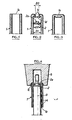
- FIGS. 1 to 3 schematically illustrate the method of manufacturing a welded bottom tube according to the present invention
- Figure 4 illustrates the implementation of the process of FIGS. 1 to 3 by means of two welding electrodes, of suitable shapes
- 1 designates a weldable steel tube of internal diameter D1 and of suitable dimensions to constitute a gas spring under high pressure.
- FIG. 1 there is only shown the part of this tube which is close to that of its ends 1a, which must be closed to form the bottom.
- the edge of this end 1a is folded towards the inside of the tube, as indicated in 1c in FIG. 2, for example by crimping, by rolling, by crusting, or by a similar method.
- a nozzle 2 is then made of weldable steel, the transverse dimensions of which, in particular the diameter D2, is between the diameter D3 of the opening 1d (FIG. 2) delimited by the folded edge 1c of the tube, and the internal diameter D1 of said tube.
- the end piece 2 is engaged inside the tube 1 by its second open end so as to bring the end piece 2 into contact with the folded edge 1c, to which the end piece 2 is then welded by any suitable method.
- the metal patch which constitutes the end piece 2 has in its middle a cylindrical projection 2a (FIG. 2) whose diameter is barely less than that of the opening 1d, and the height of which can be chosen so that the bottom 1e of the tube 1 (FIG. 3) has, after welding, an almost smooth external face, just like its internal face. This not only improves the aesthetic appearance of the welded bottom tube, but also effectively protects its weld against corrosion.
- the present invention is not limited to the embodiment described above. It encompasses all of its variants, only a few of which will be indicated below, by way of non-limiting examples.
- the shape of the welding electrodes as well as their movements of approaching and moving away are optional materials, as is the shape of the underside of the upper electrode.
- the shape of the nozzle 2, and in particular of its upper face (in FIG. 2), is optional material; the tip 2 can be constituted by a simple metallic tablet with flat and parallel faces.
- the shape of the folded edge of the first open end of the tube is also optional; it depends in particular on the process used for this purpose; for example, the edge folded inwards from the tube could be applied against its internal wall.
Landscapes
- Engineering & Computer Science (AREA)
- General Engineering & Computer Science (AREA)
- Mechanical Engineering (AREA)
- Arc Welding In General (AREA)
- Vehicle Body Suspensions (AREA)
- Rigid Pipes And Flexible Pipes (AREA)
- Piles And Underground Anchors (AREA)
- Springs (AREA)
- Connections Arranged To Contact A Plurality Of Conductors (AREA)
- Butt Welding And Welding Of Specific Article (AREA)
- Fluid-Damping Devices (AREA)
- Pressure Welding/Diffusion-Bonding (AREA)
Priority Applications (1)
| Application Number | Priority Date | Filing Date | Title |
|---|---|---|---|
| AT84402561T ATE35783T1 (de) | 1983-12-16 | 1984-12-12 | Rohre mit geschweisstem boden, insbesondere zum herstellen eines hochdruckgasdaempfers. |
Applications Claiming Priority (2)
| Application Number | Priority Date | Filing Date | Title |
|---|---|---|---|
| FR8320187 | 1983-12-16 | ||
| FR8320187A FR2556622B1 (fr) | 1983-12-16 | 1983-12-16 | Tube a fond soude, notamment pour la realisation d'un ressort a gaz sous forte pression |
Publications (2)
| Publication Number | Publication Date |
|---|---|
| EP0149384A1 true EP0149384A1 (de) | 1985-07-24 |
| EP0149384B1 EP0149384B1 (de) | 1988-07-20 |
Family
ID=9295253
Family Applications (1)
| Application Number | Title | Priority Date | Filing Date |
|---|---|---|---|
| EP84402561A Expired EP0149384B1 (de) | 1983-12-16 | 1984-12-12 | Rohre mit geschweisstem Boden, insbesondere zum Herstellen eines Hochdruckgasdämpfers |
Country Status (7)
| Country | Link |
|---|---|
| US (1) | US4717129A (de) |
| EP (1) | EP0149384B1 (de) |
| AT (1) | ATE35783T1 (de) |
| CA (1) | CA1222468A (de) |
| DE (1) | DE3472764D1 (de) |
| ES (2) | ES8607772A1 (de) |
| FR (1) | FR2556622B1 (de) |
Cited By (3)
| Publication number | Priority date | Publication date | Assignee | Title |
|---|---|---|---|---|
| FR2688843A1 (fr) * | 1992-03-17 | 1993-09-24 | Fichtel & Sachs Ag | Tube de cylindre et de reservoir a fond soude pour amortisseur. |
| FR2692953A1 (fr) * | 1992-06-26 | 1993-12-31 | Fichtel & Sachs Ag | Amortisseur d'oscillations et procédé de fabrication de cet amortisseur. |
| EP0653576A1 (de) * | 1993-11-09 | 1995-05-17 | Delphi France Automotive Systems | Hydraulischer Dämpfer |
Families Citing this family (4)
| Publication number | Priority date | Publication date | Assignee | Title |
|---|---|---|---|---|
| GB2197422B (en) * | 1986-11-08 | 1991-06-26 | Evertaut Limited | Height adjustment mechanism for swivel chairs and other articles of furniture |
| RU2153127C1 (ru) * | 1998-11-16 | 2000-07-20 | Закрытое акционерное общество "Компания Балко" | Баллон высокого давления и способ его изготовления |
| CN100389002C (zh) * | 2004-03-18 | 2008-05-21 | 十堰兴升工贸有限公司 | 氮气弹簧缸筒的加工工艺 |
| WO2017032348A1 (en) * | 2015-08-21 | 2017-03-02 | VITKOVICE CYLINDERS a.s. | High-pressure seamless steel cylinder with second inner neck and the method of its production |
Citations (5)
| Publication number | Priority date | Publication date | Assignee | Title |
|---|---|---|---|---|
| DE313330C (de) * | ||||
| GB376957A (en) * | 1931-07-21 | 1932-07-21 | Mannesmann Ag | Method for the manufacture of metallic hollow bodies such as flasks and the like |
| US3594894A (en) * | 1968-11-20 | 1971-07-27 | Gen Fire Extinguisher Corp | Method of forming cartridges |
| FR2395807A1 (fr) * | 1977-06-27 | 1979-01-26 | Towne Robinson Fastener Cy | Procede et machine de faconnage d'un ecrou, notamment pour fixer des roues de vehicules |
| EP0042925A2 (de) * | 1980-06-25 | 1982-01-06 | Boge GmbH | Führungskräfte aufnehmender Schwingungsdämpfer, insbesondere für Kraftfahrzeuge, mit einer hohlen Kolbenstange |
Family Cites Families (6)
| Publication number | Priority date | Publication date | Assignee | Title |
|---|---|---|---|---|
| US3315902A (en) * | 1962-08-31 | 1967-04-25 | Iowa Mfg Co Cedar Rapids | Gas hydraulic spring for crushing apparatus |
| US3366379A (en) * | 1965-10-23 | 1968-01-30 | Maremont Corp | Air spring |
| US3375002A (en) * | 1965-12-01 | 1968-03-26 | Caterpillar Tractor Co | Vehicle suspension strut |
| US4265344A (en) * | 1977-12-21 | 1981-05-05 | Tayco Developments, Inc. | Liquid spring with integral plastic body and seal and fabrication method therefor |
| JPS57165124A (en) * | 1981-04-03 | 1982-10-12 | Kayaba Ind Co Ltd | Press |
| DE3202705C2 (de) * | 1982-01-28 | 1984-11-22 | August Bilstein GmbH & Co KG, 5828 Ennepetal | Hydropneumatischer Schwingungsdämpfer für Kraftfahrzeuge |
-
1983
- 1983-12-16 FR FR8320187A patent/FR2556622B1/fr not_active Expired
-
1984
- 1984-12-12 AT AT84402561T patent/ATE35783T1/de active
- 1984-12-12 DE DE8484402561T patent/DE3472764D1/de not_active Expired
- 1984-12-12 EP EP84402561A patent/EP0149384B1/de not_active Expired
- 1984-12-14 ES ES538641A patent/ES8607772A1/es not_active Expired
- 1984-12-14 CA CA000470221A patent/CA1222468A/en not_active Expired
-
1985
- 1985-11-19 ES ES1985290413U patent/ES290413Y/es not_active Expired
-
1986
- 1986-12-19 US US06/945,237 patent/US4717129A/en not_active Expired - Fee Related
Patent Citations (5)
| Publication number | Priority date | Publication date | Assignee | Title |
|---|---|---|---|---|
| DE313330C (de) * | ||||
| GB376957A (en) * | 1931-07-21 | 1932-07-21 | Mannesmann Ag | Method for the manufacture of metallic hollow bodies such as flasks and the like |
| US3594894A (en) * | 1968-11-20 | 1971-07-27 | Gen Fire Extinguisher Corp | Method of forming cartridges |
| FR2395807A1 (fr) * | 1977-06-27 | 1979-01-26 | Towne Robinson Fastener Cy | Procede et machine de faconnage d'un ecrou, notamment pour fixer des roues de vehicules |
| EP0042925A2 (de) * | 1980-06-25 | 1982-01-06 | Boge GmbH | Führungskräfte aufnehmender Schwingungsdämpfer, insbesondere für Kraftfahrzeuge, mit einer hohlen Kolbenstange |
Non-Patent Citations (1)
| Title |
|---|
| PATENTS ABSTRACTS OF JAPAN, vol. 7, no. 5 (M-184)[1150], 11 janvier 1983; & JP - A - 57 165 124 (KAYABA KOGYO K.K.) 12-10-1982 * |
Cited By (4)
| Publication number | Priority date | Publication date | Assignee | Title |
|---|---|---|---|---|
| FR2688843A1 (fr) * | 1992-03-17 | 1993-09-24 | Fichtel & Sachs Ag | Tube de cylindre et de reservoir a fond soude pour amortisseur. |
| ES2062939A2 (es) * | 1992-03-17 | 1994-12-16 | Fichtel & Sachs Ag | Tubo en forma de cilindro/recipiente con fondo soldado para un amortiguador de vibraciones. |
| FR2692953A1 (fr) * | 1992-06-26 | 1993-12-31 | Fichtel & Sachs Ag | Amortisseur d'oscillations et procédé de fabrication de cet amortisseur. |
| EP0653576A1 (de) * | 1993-11-09 | 1995-05-17 | Delphi France Automotive Systems | Hydraulischer Dämpfer |
Also Published As
| Publication number | Publication date |
|---|---|
| ES8607772A1 (es) | 1986-06-01 |
| EP0149384B1 (de) | 1988-07-20 |
| FR2556622A1 (fr) | 1985-06-21 |
| DE3472764D1 (en) | 1988-08-25 |
| ES290413U (es) | 1986-03-16 |
| ES290413Y (es) | 1986-10-16 |
| ATE35783T1 (de) | 1988-08-15 |
| ES538641A0 (es) | 1986-06-01 |
| FR2556622B1 (fr) | 1987-12-11 |
| US4717129A (en) | 1988-01-05 |
| CA1222468A (en) | 1987-06-02 |
Similar Documents
| Publication | Publication Date | Title |
|---|---|---|
| CH440007A (fr) | Récipient en matière plastique | |
| EP1221728B1 (de) | Wiederverschliessbares Ventil und dieses Ventil enthaltender elektrochemischer Generator | |
| EP0149384A1 (de) | Rohre mit geschweisstem Boden, insbesondere zum Herstellen eines Hochdruckgasdämpfers | |
| FR2792392A1 (fr) | Dispositif de protection d'un recipient et recipient equipe de ce dispositif | |
| CA3147515A1 (fr) | Coupelle de valve pour recipient sous pression | |
| EP2931454B1 (de) | Montageverfahren mit magnetischem bördeln | |
| CA2863347C (fr) | Procede de fabrication d'un ensemble de stockage d'energie electrique | |
| EP0095976B1 (de) | Verfahren zum Schweissen von zwei Teilen | |
| FR2750906A1 (fr) | Procede de formation d'une nervure sur une partie de tuyau male | |
| FR2677137A1 (fr) | Procede de reparation d'un microtube a fibres optiques. | |
| EP0642875A1 (de) | Verfahren und Vorrichtung zum Herstellen von Flüssiggasflaschen, und hergestellte Flaschen | |
| FR2482779A1 (fr) | Tube cathodique de securite aux explosions | |
| FR2530744A1 (fr) | Reservoir de pression tel qu'accumulateur de pression et son procede de fabrication | |
| EP0061400A1 (de) | Verfahren und Vorrichtung zum dichten Verschliessen und zum Öffnen eines Behälters für bestrahlten Kernbrennstoff | |
| FR2730213A1 (fr) | Procede de fabrication d'un emballage metallique de forme generale prismatique et emballage obtenu par ce procede | |
| EP1219873A1 (de) | Eingepresste Ventildichtung und Herstellungsverfahren für dieselbe | |
| FR2947246A1 (fr) | Tete de sertissage d'elements sertissables sur des flacons | |
| WO2000042342A2 (fr) | Dispositif de branchement d'une canalisation de derivation sur une canalisation de transport de fluide | |
| WO2016107888A1 (fr) | Dispositif d'electro-hydroformage | |
| FR2492050A1 (fr) | Procede de fabrication de reservoirs pour fluides sous pression | |
| EP0577503B1 (de) | Verfahren zum Herstellen einer Dose bestehend aus einem Metallischen Körper und Deckel und nach diesen Verfahren hergestellte Dose | |
| BE1005006A3 (fr) | Recipient de stockage final de dechets hautement radio-actifs degageant de la chaleur. | |
| EP0890779A1 (de) | Verfahren zum Verschliessen eines Rohres mittels Anschweissdeckel | |
| EP0669177B1 (de) | Metalldose für stürzbaren Inhalt bestehend aus einer Zarge und einem nach Öffnung wiederverschliessbaren Deckel, und Herstellungsverfahren einer solchen Dose | |
| FR2656246A1 (fr) | Procede de soudage electrique par points d'elements filtrants metalliques. |
Legal Events
| Date | Code | Title | Description |
|---|---|---|---|
| PUAI | Public reference made under article 153(3) epc to a published international application that has entered the european phase |
Free format text: ORIGINAL CODE: 0009012 |
|
| AK | Designated contracting states |
Designated state(s): AT BE CH DE FR GB IT LI LU NL SE |
|
| 17P | Request for examination filed |
Effective date: 19860110 |
|
| 17Q | First examination report despatched |
Effective date: 19860626 |
|
| R17C | First examination report despatched (corrected) |
Effective date: 19870327 |
|
| GRAA | (expected) grant |
Free format text: ORIGINAL CODE: 0009210 |
|
| RAP1 | Party data changed (applicant data changed or rights of an application transferred) |
Owner name: AIRAX |
|
| AK | Designated contracting states |
Kind code of ref document: B1 Designated state(s): AT BE CH DE FR GB IT LI LU NL SE |
|
| REF | Corresponds to: |
Ref document number: 35783 Country of ref document: AT Date of ref document: 19880815 Kind code of ref document: T |
|
| ITF | It: translation for a ep patent filed | ||
| REF | Corresponds to: |
Ref document number: 3472764 Country of ref document: DE Date of ref document: 19880825 |
|
| GBT | Gb: translation of ep patent filed (gb section 77(6)(a)/1977) | ||
| PLBE | No opposition filed within time limit |
Free format text: ORIGINAL CODE: 0009261 |
|
| STAA | Information on the status of an ep patent application or granted ep patent |
Free format text: STATUS: NO OPPOSITION FILED WITHIN TIME LIMIT |
|
| 26N | No opposition filed | ||
| ITTA | It: last paid annual fee | ||
| PGFP | Annual fee paid to national office [announced via postgrant information from national office to epo] |
Ref country code: AT Payment date: 19921019 Year of fee payment: 9 |
|
| PGFP | Annual fee paid to national office [announced via postgrant information from national office to epo] |
Ref country code: SE Payment date: 19921214 Year of fee payment: 9 Ref country code: CH Payment date: 19921214 Year of fee payment: 9 |
|
| PGFP | Annual fee paid to national office [announced via postgrant information from national office to epo] |
Ref country code: NL Payment date: 19921231 Year of fee payment: 9 |
|
| PGFP | Annual fee paid to national office [announced via postgrant information from national office to epo] |
Ref country code: LU Payment date: 19930105 Year of fee payment: 9 |
|
| PGFP | Annual fee paid to national office [announced via postgrant information from national office to epo] |
Ref country code: BE Payment date: 19930115 Year of fee payment: 9 |
|
| EPTA | Lu: last paid annual fee | ||
| PG25 | Lapsed in a contracting state [announced via postgrant information from national office to epo] |
Ref country code: LU Free format text: LAPSE BECAUSE OF NON-PAYMENT OF DUE FEES Effective date: 19931212 Ref country code: AT Effective date: 19931212 |
|
| PG25 | Lapsed in a contracting state [announced via postgrant information from national office to epo] |
Ref country code: SE Effective date: 19931213 |
|
| PG25 | Lapsed in a contracting state [announced via postgrant information from national office to epo] |
Ref country code: LI Effective date: 19931231 Ref country code: CH Effective date: 19931231 Ref country code: BE Effective date: 19931231 |
|
| BERE | Be: lapsed |
Owner name: AIRAX Effective date: 19931231 |
|
| PG25 | Lapsed in a contracting state [announced via postgrant information from national office to epo] |
Ref country code: NL Effective date: 19940701 |
|
| NLV4 | Nl: lapsed or anulled due to non-payment of the annual fee | ||
| REG | Reference to a national code |
Ref country code: CH Ref legal event code: PL |
|
| EUG | Se: european patent has lapsed |
Ref document number: 84402561.9 Effective date: 19940710 |
|
| REG | Reference to a national code |
Ref country code: GB Ref legal event code: IF02 |
|
| PGFP | Annual fee paid to national office [announced via postgrant information from national office to epo] |
Ref country code: GB Payment date: 20031210 Year of fee payment: 20 Ref country code: FR Payment date: 20031210 Year of fee payment: 20 |
|
| PGFP | Annual fee paid to national office [announced via postgrant information from national office to epo] |
Ref country code: DE Payment date: 20031229 Year of fee payment: 20 |
|
| PG25 | Lapsed in a contracting state [announced via postgrant information from national office to epo] |
Ref country code: GB Free format text: LAPSE BECAUSE OF EXPIRATION OF PROTECTION Effective date: 20041211 |
|
| REG | Reference to a national code |
Ref country code: GB Ref legal event code: PE20 |