EP0653576A1 - Hydraulischer Dämpfer - Google Patents
Hydraulischer Dämpfer Download PDFInfo
- Publication number
- EP0653576A1 EP0653576A1 EP94202965A EP94202965A EP0653576A1 EP 0653576 A1 EP0653576 A1 EP 0653576A1 EP 94202965 A EP94202965 A EP 94202965A EP 94202965 A EP94202965 A EP 94202965A EP 0653576 A1 EP0653576 A1 EP 0653576A1
- Authority
- EP
- European Patent Office
- Prior art keywords
- tube
- extruded
- hydraulic damper
- aluminium
- closed
- Prior art date
- Legal status (The legal status is an assumption and is not a legal conclusion. Google has not performed a legal analysis and makes no representation as to the accuracy of the status listed.)
- Granted
Links
- 229910000838 Al alloy Inorganic materials 0.000 claims abstract description 13
- XAGFODPZIPBFFR-UHFFFAOYSA-N aluminium Chemical compound [Al] XAGFODPZIPBFFR-UHFFFAOYSA-N 0.000 claims abstract description 12
- 229910052782 aluminium Inorganic materials 0.000 claims abstract description 12
- 239000004411 aluminium Substances 0.000 claims abstract description 12
- 238000005096 rolling process Methods 0.000 claims description 9
- 238000000034 method Methods 0.000 claims description 8
- 238000010438 heat treatment Methods 0.000 claims description 5
- 238000001125 extrusion Methods 0.000 claims 2
- 238000003780 insertion Methods 0.000 claims 1
- 230000037431 insertion Effects 0.000 claims 1
- 238000004519 manufacturing process Methods 0.000 abstract description 2
- 230000006835 compression Effects 0.000 description 8
- 238000007906 compression Methods 0.000 description 8
- 239000012530 fluid Substances 0.000 description 5
- 238000003466 welding Methods 0.000 description 4
- 229910000831 Steel Inorganic materials 0.000 description 3
- 239000011324 bead Substances 0.000 description 3
- 239000010959 steel Substances 0.000 description 3
- 239000000725 suspension Substances 0.000 description 3
- 238000005452 bending Methods 0.000 description 2
- 230000015572 biosynthetic process Effects 0.000 description 2
- 238000003825 pressing Methods 0.000 description 2
- 238000007789 sealing Methods 0.000 description 2
- 239000006096 absorbing agent Substances 0.000 description 1
- 239000000853 adhesive Substances 0.000 description 1
- 230000001070 adhesive effect Effects 0.000 description 1
- 229910052804 chromium Inorganic materials 0.000 description 1
- 229910052802 copper Inorganic materials 0.000 description 1
- 230000007797 corrosion Effects 0.000 description 1
- 238000005260 corrosion Methods 0.000 description 1
- 238000005520 cutting process Methods 0.000 description 1
- 230000017525 heat dissipation Effects 0.000 description 1
- 239000012535 impurity Substances 0.000 description 1
- 229910052742 iron Inorganic materials 0.000 description 1
- 229910052748 manganese Inorganic materials 0.000 description 1
- 239000000463 material Substances 0.000 description 1
- 239000000203 mixture Substances 0.000 description 1
- 230000004048 modification Effects 0.000 description 1
- 238000012986 modification Methods 0.000 description 1
- 230000035939 shock Effects 0.000 description 1
- 238000009987 spinning Methods 0.000 description 1
- 229910052725 zinc Inorganic materials 0.000 description 1
Images


Classifications
-
- B—PERFORMING OPERATIONS; TRANSPORTING
- B60—VEHICLES IN GENERAL
- B60G—VEHICLE SUSPENSION ARRANGEMENTS
- B60G15/00—Resilient suspensions characterised by arrangement, location or type of combined spring and vibration damper, e.g. telescopic type
- B60G15/02—Resilient suspensions characterised by arrangement, location or type of combined spring and vibration damper, e.g. telescopic type having mechanical spring
- B60G15/06—Resilient suspensions characterised by arrangement, location or type of combined spring and vibration damper, e.g. telescopic type having mechanical spring and fluid damper
- B60G15/07—Resilient suspensions characterised by arrangement, location or type of combined spring and vibration damper, e.g. telescopic type having mechanical spring and fluid damper the damper being connected to the stub axle and the spring being arranged around the damper
-
- B—PERFORMING OPERATIONS; TRANSPORTING
- B60—VEHICLES IN GENERAL
- B60G—VEHICLE SUSPENSION ARRANGEMENTS
- B60G13/00—Resilient suspensions characterised by arrangement, location or type of vibration dampers
- B60G13/001—Arrangements for attachment of dampers
- B60G13/005—Arrangements for attachment of dampers characterised by the mounting on the axle or suspension arm of the damper unit
- B60G13/006—Arrangements for attachment of dampers characterised by the mounting on the axle or suspension arm of the damper unit on the stub axle
-
- B—PERFORMING OPERATIONS; TRANSPORTING
- B60—VEHICLES IN GENERAL
- B60G—VEHICLE SUSPENSION ARRANGEMENTS
- B60G15/00—Resilient suspensions characterised by arrangement, location or type of combined spring and vibration damper, e.g. telescopic type
- B60G15/02—Resilient suspensions characterised by arrangement, location or type of combined spring and vibration damper, e.g. telescopic type having mechanical spring
- B60G15/06—Resilient suspensions characterised by arrangement, location or type of combined spring and vibration damper, e.g. telescopic type having mechanical spring and fluid damper
- B60G15/062—Resilient suspensions characterised by arrangement, location or type of combined spring and vibration damper, e.g. telescopic type having mechanical spring and fluid damper the spring being arranged around the damper
- B60G15/063—Resilient suspensions characterised by arrangement, location or type of combined spring and vibration damper, e.g. telescopic type having mechanical spring and fluid damper the spring being arranged around the damper characterised by the mounting of the spring on the damper
-
- F—MECHANICAL ENGINEERING; LIGHTING; HEATING; WEAPONS; BLASTING
- F16—ENGINEERING ELEMENTS AND UNITS; GENERAL MEASURES FOR PRODUCING AND MAINTAINING EFFECTIVE FUNCTIONING OF MACHINES OR INSTALLATIONS; THERMAL INSULATION IN GENERAL
- F16F—SPRINGS; SHOCK-ABSORBERS; MEANS FOR DAMPING VIBRATION
- F16F9/00—Springs, vibration-dampers, shock-absorbers, or similarly-constructed movement-dampers using a fluid or the equivalent as damping medium
- F16F9/32—Details
- F16F9/3207—Constructional features
- F16F9/3235—Constructional features of cylinders
-
- F—MECHANICAL ENGINEERING; LIGHTING; HEATING; WEAPONS; BLASTING
- F16—ENGINEERING ELEMENTS AND UNITS; GENERAL MEASURES FOR PRODUCING AND MAINTAINING EFFECTIVE FUNCTIONING OF MACHINES OR INSTALLATIONS; THERMAL INSULATION IN GENERAL
- F16F—SPRINGS; SHOCK-ABSORBERS; MEANS FOR DAMPING VIBRATION
- F16F9/00—Springs, vibration-dampers, shock-absorbers, or similarly-constructed movement-dampers using a fluid or the equivalent as damping medium
- F16F9/32—Details
- F16F9/3271—Assembly or repair
-
- F—MECHANICAL ENGINEERING; LIGHTING; HEATING; WEAPONS; BLASTING
- F16—ENGINEERING ELEMENTS AND UNITS; GENERAL MEASURES FOR PRODUCING AND MAINTAINING EFFECTIVE FUNCTIONING OF MACHINES OR INSTALLATIONS; THERMAL INSULATION IN GENERAL
- F16F—SPRINGS; SHOCK-ABSORBERS; MEANS FOR DAMPING VIBRATION
- F16F9/00—Springs, vibration-dampers, shock-absorbers, or similarly-constructed movement-dampers using a fluid or the equivalent as damping medium
- F16F9/32—Details
- F16F9/54—Arrangements for attachment
-
- B—PERFORMING OPERATIONS; TRANSPORTING
- B60—VEHICLES IN GENERAL
- B60G—VEHICLE SUSPENSION ARRANGEMENTS
- B60G2202/00—Indexing codes relating to the type of spring, damper or actuator
- B60G2202/30—Spring/Damper and/or actuator Units
- B60G2202/31—Spring/Damper and/or actuator Units with the spring arranged around the damper, e.g. MacPherson strut
- B60G2202/312—The spring being a wound spring
-
- B—PERFORMING OPERATIONS; TRANSPORTING
- B60—VEHICLES IN GENERAL
- B60G—VEHICLE SUSPENSION ARRANGEMENTS
- B60G2204/00—Indexing codes related to suspensions per se or to auxiliary parts
- B60G2204/10—Mounting of suspension elements
- B60G2204/12—Mounting of springs or dampers
-
- B—PERFORMING OPERATIONS; TRANSPORTING
- B60—VEHICLES IN GENERAL
- B60G—VEHICLE SUSPENSION ARRANGEMENTS
- B60G2204/00—Indexing codes related to suspensions per se or to auxiliary parts
- B60G2204/10—Mounting of suspension elements
- B60G2204/12—Mounting of springs or dampers
- B60G2204/124—Mounting of coil springs
- B60G2204/1242—Mounting of coil springs on a damper, e.g. MacPerson strut
-
- B—PERFORMING OPERATIONS; TRANSPORTING
- B60—VEHICLES IN GENERAL
- B60G—VEHICLE SUSPENSION ARRANGEMENTS
- B60G2204/00—Indexing codes related to suspensions per se or to auxiliary parts
- B60G2204/10—Mounting of suspension elements
- B60G2204/12—Mounting of springs or dampers
- B60G2204/129—Damper mount on wheel suspension or knuckle
-
- B—PERFORMING OPERATIONS; TRANSPORTING
- B60—VEHICLES IN GENERAL
- B60G—VEHICLE SUSPENSION ARRANGEMENTS
- B60G2204/00—Indexing codes related to suspensions per se or to auxiliary parts
- B60G2204/40—Auxiliary suspension parts; Adjustment of suspensions
- B60G2204/43—Fittings, brackets or knuckles
- B60G2204/4304—Bracket for lower cylinder mount of McPherson strut
-
- B—PERFORMING OPERATIONS; TRANSPORTING
- B60—VEHICLES IN GENERAL
- B60G—VEHICLE SUSPENSION ARRANGEMENTS
- B60G2206/00—Indexing codes related to the manufacturing of suspensions: constructional features, the materials used, procedures or tools
- B60G2206/01—Constructional features of suspension elements, e.g. arms, dampers, springs
- B60G2206/40—Constructional features of dampers and/or springs
-
- B—PERFORMING OPERATIONS; TRANSPORTING
- B60—VEHICLES IN GENERAL
- B60G—VEHICLE SUSPENSION ARRANGEMENTS
- B60G2206/00—Indexing codes related to the manufacturing of suspensions: constructional features, the materials used, procedures or tools
- B60G2206/01—Constructional features of suspension elements, e.g. arms, dampers, springs
- B60G2206/40—Constructional features of dampers and/or springs
- B60G2206/41—Dampers
-
- B—PERFORMING OPERATIONS; TRANSPORTING
- B60—VEHICLES IN GENERAL
- B60G—VEHICLE SUSPENSION ARRANGEMENTS
- B60G2206/00—Indexing codes related to the manufacturing of suspensions: constructional features, the materials used, procedures or tools
- B60G2206/01—Constructional features of suspension elements, e.g. arms, dampers, springs
- B60G2206/40—Constructional features of dampers and/or springs
- B60G2206/42—Springs
- B60G2206/422—Accumulators for hydropneumatic springs
-
- B—PERFORMING OPERATIONS; TRANSPORTING
- B60—VEHICLES IN GENERAL
- B60G—VEHICLE SUSPENSION ARRANGEMENTS
- B60G2206/00—Indexing codes related to the manufacturing of suspensions: constructional features, the materials used, procedures or tools
- B60G2206/01—Constructional features of suspension elements, e.g. arms, dampers, springs
- B60G2206/80—Manufacturing procedures
- B60G2206/81—Shaping
Definitions
- This invention relates to a hydraulic damper for a motor vehicle, and to a method of forming such a hydraulic damper.
- hydraulic damper is meant a suspension strut or shock absorber.
- a hydraulic damper for use in the suspension system of a motor vehicle typically comprises a tube; a piston sealably slidably mounted in the tube and attached to a piston rod, the piston separating a compression chamber from a rebound chamber within the tube; a compression stroke valve mounted on the piston which allows fluid flow from the compression chamber to the rebound chamber; and a rebound stroke valve mounted on the piston which allows fluid flow from the rebound chamber to the compression chamber.
- the piston rod extends out of the tube at one end thereof, and is sealably slidably mounted in that one end.
- Such hydraulic dampers either comprise an inner tube and an outer tube (sometimes referred to as a twin tube damper) in which the piston sealably slides in the inner tube, or comprise a single tube (sometimes referred to as a monotube damper).
- each tube of a hydraulic damper It is usual practice to form the or each tube of a hydraulic damper by rolling a sheet of steel and welding together the adjacent longitudinal edges. External parts, such as the spring seat and the mounting bracket or steering knuckle, which are also formed from steel, are then welded to the single tube or the outer tube. The other end of the tube is sealed closed by welding on an end plate or by arc-heating and rolling the tube end, and the internal components of the suspension strut (such as those mentioned above) are inserted into the tube by way of the one end thereof, which is then sealed closed.
- the use of several welding steps has disadvantages in that welds are time consuming operations. Further, welds are susceptible to corrosion. Still further, the use of steel has disadvantages with regard to weight.
- a hydraulic damper in accordance with the present invention comprises a longitudinally extending tube, wherein the tube is formed from extruded aluminium or aluminium alloy.
- a method of forming a hydraulic damper in accordance with the present invention comprises extruding a tube of aluminium or aluminium alloy; and closing an end of the extruded tube.
- This invention removes the steps of welding, thereby removing time consuming operations. Further the use of aluminium or aluminium alloy has advantages with regard to weight when compared to previously known arrangements.
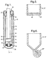
- the hydraulic damper 10 shown in Figure 1 is of the twin tube damper type, and comprises an outer tube 12, and an inner tube 14 substantially coaxial with the outer tube on an axis L.
- the outer tube 12, and preferably the inner tube 14, are formed from extruded aluminium or aluminium alloy and have a substantially constant cross-section along their length.
- the hydraulic damper 10 further comprises conventional components such as a piston assembly 16, a piston rod 18 having a longitudinal axis on axis L, a compensation valve 20, and a rod guide 22.
- the piston assembly 16 includes a compression valve and a rebound valve (not shown)
- the piston assembly 16, the compensation valve 20 and the rod guide 22 may be any suitable conventional design well known to those skilled in the art, and will not be described in detail.
- the inner tube 14 is substantially closed at one end 24 by the compensation valve 20, and is substantially closed at the other end 26 by the rod guide 22.
- the outer tube 12 is closed at one end 28 by flame heating and rolling the outer tube walls, and is substantially closed at the other end 30 (the open end) by the rod guide 22 and by spin closing the end 30 of the outer tube.
- An example of apparatus suitable for spin closing is disclosed in our GB patent application no. 9412806.3, incorporated herein by reference, in which a pair of rollers initially push a portion of the outer tube at the open end over at approximately 45°, and a second pair of rollers then push a section of the portion over at approximately 90°, whilst the outer tube is spinning about its longitudinal axis.
- the piston rod 18 extends through, and makes a sealing sliding fit with the rod guide 22.
- the piston assembly 16 makes a sealing sliding fit with the inner surface 32 of the inner tube 14.
- the piston rod 18 is secured to the piston assembly 16 by a nut 34 or any other suitable means.
- the piston assembly 16 divides the inner area of the inner tube 14 into a rebound chamber 36 and a compression chamber 38.
- the area between the inner tube 14 and the outer tube 12 defines a compensation chamber 40.
- the rebound and compression chambers 36 and 38 are substantially filled with fluid to damp reciprocating movement of the piston assembly 16 and piston rod 18 along axis L relative to the outer and inner tubes 12 and 14.
- the compensation chamber 40 is partly filled with fluid and acts as a reservoir for the fluid in the rebound and compression chambers 36 and 38.
- the hydraulic damper 10 is mounted in a motor vehicle (not shown) in any standard manner.
- Figures 2 to 4 show an alternative arrangement for the outer tube 12' of the hydraulic damper of Figure 1.
- the outer tube 12' is extruded integrally with a pair of spaced arms 42 which are substantially parallel.
- the length of the arms 42 is then reduced by a cutting operation, and pairs of holes 44 are cut in each arm to form a mounting bracket 46.
- a first external, circumferentially extending, bead 48 is then formed in the tube 12'.
- a spring seat 50 of aluminium or aluminium alloy is formed by pressing and includes a cylindrical section 52 which has an internal shape and size which is substantially the same as the external shape and size of the tube 12' - that is, the cylindrical section can make a close sliding fit on the tube.
- the spring seat 50 is slid onto the tube 12', with the tube passing through the cylindrical section 52 until one end 54 of the cylindrical section rests on the first bead 48.
- a second external, circumferentially extending, bead 56 is then formed in the tube 12' adjacent the other end 58 of the cylindrical section 52 to secure the spring seat 50 on the tube.
- the spring seat 50 may be secured by sliding the spring seat into position and then forming the two ribs, or by forming two rings of external dimples rather than ribs, or by rivets, or any other suitable alternative arrangement.
- the one end 28 of the outer tube 12' is closed by flame heating the end of the outer tube, and then rolling over the end. Having formed the outer tube 12' with the mounting bracket 46 and the spring seat 50, and having closed the one end 28, the other components of the hydraulic damper 10' can then be assembled therein.
- the one end 28 of the outer tube 12, 12' may be sealed and closed by an end plate 60 which is secured in place by pushing the end plate into the end of the extruded tube 12,12' and then rolling and pressing the tube around the end plate as shown in Figure 5.
- the one end 28'' of the extruded tube 12,12' can be closed by flattening the one end of the tube into a substantially planar formation, and then rolling the planar formation in the longitudinal direction as shown in Figure 6.
- Still further alternatives for closing the one end 28 of the extruded tube 12,12' include attaching an end cap by screw threading or adhesive.
- the other end 30 of the extruded tube 12,12' may be closed by a threaded cap as an alternative arrangement to spin closing.
- Figure 7 shows a further alternative arrangement for the extruded outer tube 12'' for the hydraulic damper 10 of Figure 1.
- the outer tube 12'' is integrally extruded with a number of inwardly directed webs 62 which extend longitudinally along the inner surface 64 of the extruded tube.
- the webs 62 have a cross-section which is between and T and Y shaped, and their inwardly directed surfaces 66 forms tips 67 which lie substantially on a circle having a diameter slightly less than the external diameter of the inner tube 14 of the hydraulic damper 10.
- the inner tube 14 (which may be of aluminium or aluminium alloy or of any other suitable material) of the hydraulic damper 10 is slid between and resiliently gripped by the webs 62 to retain the inner tube in position relative to the outer tube 12''.
- the inner tube 14 and the outer tube 12 are integrally extruded in one piece with a number of interconnecting webs 68 which extend longitudinally.
- the arrangements of Figures 7 and 8 have the additional advantage of reducing the risk of the inner tube 14 bending relative to the outer tube 12 when the hydraulic damper 10 is subjected to a bending moment between the outer tube and the piston rod 18.
- the support arrangements for the inner tube of the embodiments of Figures 7 and 8 provide increased strength for the hydraulic damper over previous designs and allow a reduction in wall thickness for the inner tube, thereby further reducing weight and cost.
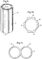
- Figure 9 shows a further modification of an extruded tube 70 in which the external surface 72 of the tube has a number of substantially identical T-shaped channels 74 extending along the length of the tube.
- cylindrical mounting sections of a spring seat and a separately formed mounting bracket or steering knuckle may be formed with correspondingly shaped ribs which allow the spring seat and the mounting bracket or steering knuckle to make a close sliding fit with the tube 70.
- the free edges 76 of the channels 74 in the tube 70 can be distorted to secure the spring seat and mounting bracket in position.
- This arrangement increases the area of the external surface 72 of the extruded tube 70, thereby providing increased heat dissipation relative to an extruded tube having a smooth external surface.
- the extruded tube 80 has two pairs of external, longitudinally (axially) extending, outwardly directed, ribs 82,84, with the ribs of each pair being diametrically opposed, and the pairs being set at right angles to one another.
- the ribs 82,84 of each pair have substantially the same cross-sectional shape and area, but different from the cross-sectional shape and area of the other pair of ribs.
- cylindrical mounting sections of a spring seat and a separately formed mounting bracket or steering knuckle may be formed with correspondingly shaped grooves which allow the spring seat and the mounting bracket or steering knuckle to make a close sliding fit with the tube 80, and also provide means for correctly locating the spring seat and mounting bracket or steering knuckle.
- a pair of tubes 90,92 are integrally extruded and extend longitudinally substantially parallel to one another.
- one of the tubes 90 acts as the inner tube of a twin tube hydraulic damper, and the other tube 92 provides the equivalent of a compensation chamber 94 for the hydraulic damper.
- the extruded tube is formed from aluminium alloy conforming to BS 6082 and which comprises, by weight percentage, 0.70 to 1.3% Si, 0.5% Fe, 0.1% Cu, 0.4 to 1.0% Mn, 0.6 to 1.2% Mg, 0.25% Cr, 0.2% Zn, 0.1% Ti, 0.05 to 0.15% impurities, with the remainder being aluminium.
- aluminium alloy conforming to BS 6082 and which comprises, by weight percentage, 0.70 to 1.3% Si, 0.5% Fe, 0.1% Cu, 0.4 to 1.0% Mn, 0.6 to 1.2% Mg, 0.25% Cr, 0.2% Zn, 0.1% Ti, 0.05 to 0.15% impurities, with the remainder being aluminium.
- Other compositions of aluminium alloy may be used.
Landscapes
- Engineering & Computer Science (AREA)
- Mechanical Engineering (AREA)
- General Engineering & Computer Science (AREA)
- Vehicle Body Suspensions (AREA)
- Fluid-Damping Devices (AREA)
- Vibration Dampers (AREA)
- Body Structure For Vehicles (AREA)
Applications Claiming Priority (3)
| Application Number | Priority Date | Filing Date | Title |
|---|---|---|---|
| GB9323047 | 1993-11-09 | ||
| GB939323047A GB9323047D0 (en) | 1993-11-09 | 1993-11-09 | A method of forming a suspension strut |
| US08/324,467 US5607035A (en) | 1994-10-13 | 1994-10-17 | Hydraulic damper |
Publications (2)
| Publication Number | Publication Date |
|---|---|
| EP0653576A1 true EP0653576A1 (de) | 1995-05-17 |
| EP0653576B1 EP0653576B1 (de) | 1998-07-22 |
Family
ID=26303826
Family Applications (3)
| Application Number | Title | Priority Date | Filing Date |
|---|---|---|---|
| EP94202965A Expired - Lifetime EP0653576B1 (de) | 1993-11-09 | 1994-10-13 | Verfahren zum Formen eines hydraulischen Dämpfers |
| EP94202968A Expired - Lifetime EP0653578B1 (de) | 1993-11-09 | 1994-10-13 | Verfahren zur Herstellung eines hydraulischen Stossdämpfers |
| EP94202967A Expired - Lifetime EP0653577B1 (de) | 1993-11-09 | 1994-10-13 | Hydraulischer Stossdämpfer |
Family Applications After (2)
| Application Number | Title | Priority Date | Filing Date |
|---|---|---|---|
| EP94202968A Expired - Lifetime EP0653578B1 (de) | 1993-11-09 | 1994-10-13 | Verfahren zur Herstellung eines hydraulischen Stossdämpfers |
| EP94202967A Expired - Lifetime EP0653577B1 (de) | 1993-11-09 | 1994-10-13 | Hydraulischer Stossdämpfer |
Country Status (5)
| Country | Link |
|---|---|
| US (1) | US5620172A (de) |
| EP (3) | EP0653576B1 (de) |
| DE (3) | DE69412751T2 (de) |
| ES (3) | ES2119068T3 (de) |
| GB (4) | GB9323047D0 (de) |
Cited By (7)
| Publication number | Priority date | Publication date | Assignee | Title |
|---|---|---|---|---|
| DE10004124C1 (de) * | 2000-01-31 | 2001-05-31 | Mannesmann Sachs Ag | Gelenkauge für ein Kolben-Zylinderaggregat |
| EP1114946A1 (de) * | 2000-01-05 | 2001-07-11 | Krupp Bilstein GmbH | Zweirohrstossdämpfer |
| FR2806768A1 (fr) * | 2000-03-22 | 2001-09-28 | Peugeot Citroen Automobiles Sa | Amortisseur de suspension |
| DE102007011100A1 (de) * | 2007-03-07 | 2008-09-11 | Volkswagen Ag | Zweirohrdämpfer |
| DE102015209181A1 (de) * | 2015-05-20 | 2016-11-24 | Zf Friedrichshafen Ag | Zylinderrohr für einen Schwingungsdämpfer |
| CN107000527A (zh) * | 2014-12-03 | 2017-08-01 | 爱康车辆动力学有限公司 | 减震器 |
| JP2018179073A (ja) * | 2017-04-07 | 2018-11-15 | 日立オートモティブシステムズ株式会社 | 車両用ショックアブゾーバ |
Families Citing this family (38)
| Publication number | Priority date | Publication date | Assignee | Title |
|---|---|---|---|---|
| GB2297819A (en) * | 1995-02-13 | 1996-08-14 | Acg Espana Sa | Vehicle hydraulic damper with tube and stabiliser bar connector both of aluminium or aluminium alloy |
| GB2299556A (en) * | 1995-03-28 | 1996-10-09 | Lotus Car | Extruded wheel carrier |
| DE19515643C1 (de) * | 1995-04-28 | 1996-11-07 | Fichtel & Sachs Ag | Federbein mit Aluminiumbehälter |
| DE19540049C1 (de) * | 1995-10-27 | 1997-02-20 | Fichtel & Sachs Ag | Schwingungsdämpfer mit verstellbarer Dämpfkraft |
| DE19808021C2 (de) * | 1998-02-26 | 2001-07-26 | Porsche Ag | Federabstützung |
| JP4230568B2 (ja) * | 1998-07-24 | 2009-02-25 | 株式会社ショーワ | 油圧緩衝器のばねシート固定構造 |
| US6079700A (en) * | 1998-10-09 | 2000-06-27 | Chrysler Corporation | Vehicle shock absorber spring seat pad having a spring--containment peripheral flange |
| US6205979B1 (en) | 1998-11-24 | 2001-03-27 | Robert Bosch Corporation | Spring locator for damping device |
| US6418909B2 (en) | 1998-11-24 | 2002-07-16 | Robert Bosch Corporation | Low cost hydraulic damper element and method for producing the same |
| DE19909404C2 (de) * | 1999-03-05 | 2003-08-21 | Zf Sachs Ag | Zweirohrschwingungsdämpfer |
| US6443436B1 (en) * | 2001-05-29 | 2002-09-03 | Tenneco Automotive Inc. | Air spring assembly on shock absorber with combined seal |
| US7021435B2 (en) | 2003-02-07 | 2006-04-04 | Delphi Technologies, Inc. | Monotube strut with rebound cut-off feature |
| US6691840B1 (en) | 2003-02-07 | 2004-02-17 | Delphi Technologies, Inc. | MR damper with rebound cut-off feature |
| DE10332722B3 (de) * | 2003-07-18 | 2004-10-21 | Benteler Automobiltechnik Gmbh | Federteller für ein Kraftfahrzeug-Federbein |
| JP4341830B2 (ja) * | 2003-12-16 | 2009-10-14 | 株式会社ショーワ | 自動二輪車等のフロントフォーク |
| JP2005291302A (ja) * | 2004-03-31 | 2005-10-20 | Hitachi Ltd | 油圧緩衝器 |
| US7497202B2 (en) * | 2004-10-15 | 2009-03-03 | Robert Bosch Gmbh | Hydraulic damper element |
| US7275296B2 (en) * | 2004-10-29 | 2007-10-02 | Magna Structural Systems, Inc. | Method for forming a frame assembly |
| JP2006220162A (ja) * | 2005-02-08 | 2006-08-24 | Kayaba Ind Co Ltd | 緩衝器 |
| US7921881B2 (en) * | 2006-12-15 | 2011-04-12 | Millennium Industries Corporation | Fluid conduit assembly |
| CN102423996B (zh) * | 2007-02-20 | 2015-07-01 | 田纳科汽车营运公司 | 用于精确的车辆高度的定位部件和方法 |
| JP4577345B2 (ja) * | 2007-09-26 | 2010-11-10 | トヨタ自動車株式会社 | ナックル及びナックルの製造方法 |
| DE102009000164B4 (de) | 2009-01-13 | 2016-03-03 | Zf Friedrichshafen Ag | Schwingungsdämpfer mit einer Achsaufnahme |
| DE102009008235A1 (de) * | 2009-02-10 | 2010-08-12 | Zf Friedrichshafen Ag | Kolben-Zylinder-Aggregat |
| DE102009029299B4 (de) * | 2009-09-09 | 2015-12-31 | Leichtbau-Zentrum Sachsen Gmbh | Schwingungsdämpfer |
| DE102013201302A1 (de) * | 2013-01-28 | 2014-07-31 | Zf Friedrichshafen Ag | Zylinderaggregat mit einer Klebeverbindung |
| DE102014202204A1 (de) * | 2014-02-06 | 2015-08-06 | Zf Friedrichshafen Ag | Schwingungsdämpfer mit eingerolltem Verschluss |
| US9802454B2 (en) | 2014-07-28 | 2017-10-31 | Tenneco Automotive Operating Company Inc. | Plastic spring seat having integrated crash member |
| US9834058B2 (en) * | 2014-12-04 | 2017-12-05 | Sistemi Sospensioni S.P.A. | Linear actuator for adjusting the vertical position of a spring of a damper and spring unit for a vehicle suspension and damper and spring unit for a vehicle suspension comprising such an actuator |
| US9873303B2 (en) | 2016-03-22 | 2018-01-23 | Tenneco Automotive Operating Company Inc. | Damper having reinforced catcher |
| CN108591340A (zh) * | 2018-04-03 | 2018-09-28 | 安徽日发纺织机械有限公司 | 一种转杯纺纱机的双腔避振缸结构 |
| DE102019110221A1 (de) * | 2018-04-20 | 2019-10-24 | Magna Closures Inc. | Verbindungsmechanismus für ein dünnwandiges Rohr |
| US11156261B2 (en) | 2018-12-28 | 2021-10-26 | Tenneco Automotive Operating Company Inc. | Damper with multiple external control valves |
| US11143260B2 (en) | 2018-12-28 | 2021-10-12 | Tenneco Automotive Operating Company Inc. | Damper with single external control valve |
| US11118649B2 (en) | 2019-07-01 | 2021-09-14 | Tenneco Automotive Operating Company Inc. | Damper with side collector and external control valves |
| US11248677B2 (en) | 2019-07-18 | 2022-02-15 | Tenneco Automotive Operating Company Inc. | Pre-assembled piston accumulator insert device |
| US11635122B2 (en) | 2019-07-18 | 2023-04-25 | Tenneco Automotive Operating Company Inc. | Intake device for a damper having a side collector |
| JP7110476B2 (ja) * | 2019-12-04 | 2022-08-01 | 北京猫猫狗狗科技有限公司 | 片側ガイドレールイジェクト容器 |
Citations (7)
| Publication number | Priority date | Publication date | Assignee | Title |
|---|---|---|---|---|
| DE2516656A1 (de) * | 1975-04-16 | 1976-10-28 | Boge Gmbh | Rohrgehaeuse eines teleskopschwingungsdaempfers, insbesondere fuer kraftfahrzeuge |
| FR2376971A1 (fr) * | 1977-01-10 | 1978-08-04 | Iao Industrie Riunite Spa | Ressort pneumatique et procede pour sa fabrication |
| EP0149384A1 (de) * | 1983-12-16 | 1985-07-24 | Airaxs.A. | Rohre mit geschweisstem Boden, insbesondere zum Herstellen eines Hochdruckgasdämpfers |
| DE3939012A1 (de) * | 1989-11-25 | 1991-05-29 | Boge Ag | Schwingungsdaempfer fuer ein kraftfahrzeug |
| DE9109019U1 (de) * | 1991-07-22 | 1991-10-10 | Fichtel & Sachs Ag, 8720 Schweinfurt | Zylinderrohrendkappe für einen Schwingungsdämpfer |
| JPH04158946A (ja) * | 1990-10-23 | 1992-06-02 | Atsugi Unisia Corp | 液圧式緩衝器用リザーバチューブの製造方法 |
| DE4102002A1 (de) * | 1991-01-24 | 1992-07-30 | Bayerische Motoren Werke Ag | Stossdaempfer |
Family Cites Families (27)
| Publication number | Priority date | Publication date | Assignee | Title |
|---|---|---|---|---|
| DE848457C (de) * | 1949-12-04 | 1952-09-04 | Hemscheidt Maschf Hermann | Hydraulischer Schwingungsdaempfer, insbesondere Teleskopdaempfer fuer Kraftfahrzeuge mit Zylinderrohr und Zylinderdeckel mit Aufhaengeoese |
| US2999678A (en) * | 1959-09-08 | 1961-09-12 | Heckethorn Mfg & Supply Compan | Auxiliary spring suspensions |
| DE1931028U (de) * | 1965-11-24 | 1966-01-13 | Alcan Aluminiumwerke | Gleitrohr. |
| GB1356261A (en) * | 1970-11-17 | 1974-06-12 | Girling Ltd | Vehicle suspension units |
| US3912054A (en) * | 1974-11-25 | 1975-10-14 | Brian K Fabre | Valve replacement assembly for motorcycle front forks |
| FR2437310A1 (fr) * | 1978-09-28 | 1980-04-25 | Allinquant J G | Dispositif de fixation des amortisseurs telescopiques de suspension |
| US4212087A (en) * | 1978-11-16 | 1980-07-15 | Mortensen Lavaugh L | Prosthetic leg with a hydraulic control |
| JPS55140607A (en) * | 1979-04-18 | 1980-11-04 | Nissan Motor Co Ltd | Strut-type suspender |
| US4214737A (en) * | 1979-05-11 | 1980-07-29 | Blatt Leland F | Adjustable shock absorber including metering pin and reservoir structure |
| DE3017106A1 (de) * | 1980-05-03 | 1981-11-05 | Aluminium-Walzwerke Singen Gmbh, 7700 Singen | Verfahren zum herstellen massiv umgeformter leichtmetallgegenstaende sowie formkoerper mit einem leichtmetallteil |
| DE3105170A1 (de) * | 1981-02-13 | 1982-09-02 | Fichtel & Sachs Ag, 8720 Schweinfurt | Schwingungsdaempfer oder federbein mit mindestens einem am behaelterrohr angeordneten beschlag |
| DE3128723A1 (de) * | 1981-07-21 | 1983-02-10 | Fichtel & Sachs Ag, 8720 Schweinfurt | Hydropneumatischer zweirohr-schwingungsdaempfer oder federbeineinsatz mit einer verschlusskappe fuer ein behaelterrohr |
| JPS58196343A (ja) * | 1982-05-13 | 1983-11-15 | Showa Mfg Co Ltd | 油圧緩衝器のばね受け溶接方法 |
| US4667941A (en) * | 1983-02-09 | 1987-05-26 | Kabushiki Kaisha Showa Seisakusho | Self-leveling damper for motorcycles |
| DE3312753C2 (de) * | 1983-04-09 | 1996-05-09 | Fichtel & Sachs Ag | Federbein mit Achsschenkelaufnahme |
| GB8501022D0 (en) * | 1984-01-17 | 1985-02-20 | Fichtel & Sachs Ag | Combination shock-absorber spring unit |
| US4657228A (en) * | 1985-02-25 | 1987-04-14 | Lautzenhiser John L | Gas-actuated shock absorber for aircraft |
| DE8510058U1 (de) * | 1985-04-04 | 1985-07-04 | Fichtel & Sachs Ag, 8720 Schweinfurt | Federbein mit einem auf einem Federbeinbehälter lösbar angeordneten Federteller |
| US4913268A (en) * | 1986-12-05 | 1990-04-03 | Ford Motor Company | Weldless automotive shock absorber |
| GB8905429D0 (en) * | 1989-03-09 | 1989-04-19 | Salter Ind Measurement Ltd | Piston and cylinder arrangement |
| JPH02253026A (ja) * | 1989-03-27 | 1990-10-11 | Mazda Motor Corp | 車両のストラットマウント構造 |
| US4962834A (en) * | 1989-06-14 | 1990-10-16 | Walter K. Napoleon | Threaded removable end mount system for shock absorbers |
| DE4129644A1 (de) * | 1991-09-06 | 1993-03-11 | Bayerische Motoren Werke Ag | Spurhebel-federbeineinheit fuer eine obenliegende lenkung eines kraftfahrzeuges |
| DE4129645A1 (de) * | 1991-09-06 | 1993-03-11 | Bayerische Motoren Werke Ag | Spurhebel-federbeineinheit fuer eine obenliegende lenkung eines kraftfahrzeugs und ein verfahren zur herstellung eines spurhebels fuer eine spurhebel-federbeineinheit |
| JP3118296B2 (ja) * | 1991-12-26 | 2000-12-18 | ユニプレス株式会社 | アルミ製エンジンマウント用ブラケットの製造法 |
| DE4201837C2 (de) * | 1992-01-24 | 1999-07-15 | Porsche Ag | Federbein |
| US5450908A (en) * | 1993-04-14 | 1995-09-19 | Krause Plow Corporation, Inc. | Spring-cushioned hydraulic depth control system for tillage implements |
-
1993
- 1993-11-09 GB GB939323047A patent/GB9323047D0/en active Pending
-
1994
- 1994-10-13 ES ES94202965T patent/ES2119068T3/es not_active Expired - Lifetime
- 1994-10-13 DE DE69412751T patent/DE69412751T2/de not_active Expired - Lifetime
- 1994-10-13 ES ES94202967T patent/ES2119958T3/es not_active Expired - Lifetime
- 1994-10-13 DE DE69411854T patent/DE69411854T2/de not_active Expired - Fee Related
- 1994-10-13 ES ES94202968T patent/ES2119069T3/es not_active Expired - Lifetime
- 1994-10-13 EP EP94202965A patent/EP0653576B1/de not_active Expired - Lifetime
- 1994-10-13 EP EP94202968A patent/EP0653578B1/de not_active Expired - Lifetime
- 1994-10-13 GB GB9420640A patent/GB2283713B/en not_active Expired - Fee Related
- 1994-10-13 GB GB9420639A patent/GB2283712B/en not_active Expired - Fee Related
- 1994-10-13 DE DE69411853T patent/DE69411853T2/de not_active Expired - Fee Related
- 1994-10-13 EP EP94202967A patent/EP0653577B1/de not_active Expired - Lifetime
- 1994-10-13 GB GB9420637A patent/GB2283711B/en not_active Expired - Fee Related
-
1995
- 1995-01-30 US US08/380,549 patent/US5620172A/en not_active Expired - Fee Related
Patent Citations (7)
| Publication number | Priority date | Publication date | Assignee | Title |
|---|---|---|---|---|
| DE2516656A1 (de) * | 1975-04-16 | 1976-10-28 | Boge Gmbh | Rohrgehaeuse eines teleskopschwingungsdaempfers, insbesondere fuer kraftfahrzeuge |
| FR2376971A1 (fr) * | 1977-01-10 | 1978-08-04 | Iao Industrie Riunite Spa | Ressort pneumatique et procede pour sa fabrication |
| EP0149384A1 (de) * | 1983-12-16 | 1985-07-24 | Airaxs.A. | Rohre mit geschweisstem Boden, insbesondere zum Herstellen eines Hochdruckgasdämpfers |
| DE3939012A1 (de) * | 1989-11-25 | 1991-05-29 | Boge Ag | Schwingungsdaempfer fuer ein kraftfahrzeug |
| JPH04158946A (ja) * | 1990-10-23 | 1992-06-02 | Atsugi Unisia Corp | 液圧式緩衝器用リザーバチューブの製造方法 |
| DE4102002A1 (de) * | 1991-01-24 | 1992-07-30 | Bayerische Motoren Werke Ag | Stossdaempfer |
| DE9109019U1 (de) * | 1991-07-22 | 1991-10-10 | Fichtel & Sachs Ag, 8720 Schweinfurt | Zylinderrohrendkappe für einen Schwingungsdämpfer |
Non-Patent Citations (1)
| Title |
|---|
| PATENT ABSTRACTS OF JAPAN vol. 16, no. 452 (M - 1313) 21 September 1992 (1992-09-21) * |
Cited By (8)
| Publication number | Priority date | Publication date | Assignee | Title |
|---|---|---|---|---|
| EP1114946A1 (de) * | 2000-01-05 | 2001-07-11 | Krupp Bilstein GmbH | Zweirohrstossdämpfer |
| DE10004124C1 (de) * | 2000-01-31 | 2001-05-31 | Mannesmann Sachs Ag | Gelenkauge für ein Kolben-Zylinderaggregat |
| FR2806768A1 (fr) * | 2000-03-22 | 2001-09-28 | Peugeot Citroen Automobiles Sa | Amortisseur de suspension |
| DE102007011100A1 (de) * | 2007-03-07 | 2008-09-11 | Volkswagen Ag | Zweirohrdämpfer |
| CN107000527A (zh) * | 2014-12-03 | 2017-08-01 | 爱康车辆动力学有限公司 | 减震器 |
| CN107000527B (zh) * | 2014-12-03 | 2019-08-27 | 爱康车辆动力学有限公司 | 减震器 |
| DE102015209181A1 (de) * | 2015-05-20 | 2016-11-24 | Zf Friedrichshafen Ag | Zylinderrohr für einen Schwingungsdämpfer |
| JP2018179073A (ja) * | 2017-04-07 | 2018-11-15 | 日立オートモティブシステムズ株式会社 | 車両用ショックアブゾーバ |
Also Published As
| Publication number | Publication date |
|---|---|
| GB2283712A (en) | 1995-05-17 |
| ES2119068T3 (es) | 1998-10-01 |
| EP0653576B1 (de) | 1998-07-22 |
| GB9323047D0 (en) | 1994-01-05 |
| DE69411854T2 (de) | 1998-12-03 |
| GB9420640D0 (en) | 1994-11-30 |
| GB2283711B (en) | 1997-04-09 |
| EP0653578A1 (de) | 1995-05-17 |
| EP0653577A1 (de) | 1995-05-17 |
| EP0653577B1 (de) | 1998-08-26 |
| EP0653578B1 (de) | 1998-07-22 |
| DE69412751T2 (de) | 1999-01-14 |
| DE69411854D1 (de) | 1998-08-27 |
| DE69411853D1 (de) | 1998-08-27 |
| GB2283713A (en) | 1995-05-17 |
| US5620172A (en) | 1997-04-15 |
| DE69412751D1 (de) | 1998-10-01 |
| GB9420639D0 (en) | 1994-11-30 |
| GB9420637D0 (en) | 1994-11-30 |
| GB2283713B (en) | 1997-04-09 |
| ES2119069T3 (es) | 1998-10-01 |
| DE69411853T2 (de) | 1998-12-03 |
| ES2119958T3 (es) | 1998-10-16 |
| GB2283711A (en) | 1995-05-17 |
| GB2283712B (en) | 1997-04-09 |
Similar Documents
| Publication | Publication Date | Title |
|---|---|---|
| EP0653576A1 (de) | Hydraulischer Dämpfer | |
| US5607035A (en) | Hydraulic damper | |
| US11384810B2 (en) | Damper with two-piece shell | |
| DE1181565B (de) | Teleskop-Fluessigkeitsstossdaempfer, insbesondere fuer Kraftfahrzeuge | |
| EP3263945B1 (de) | Einzelrohr-federbein mit lagerhülse mit radialem vorsprung | |
| US5570763A (en) | Suspension strut | |
| EP3816473B1 (de) | Halterung zur befestigung mit einer hydraulischen dämpferanordnung und verfahren zur verbindung einer halterung und einer hydraulischen dämpferanordnung | |
| US5794743A (en) | Shock absorber or vibration damper | |
| GB2050561A (en) | Outer Tube of Telescopic Shock Absorber | |
| US11009095B2 (en) | Damper with monolithic base | |
| JP3433772B2 (ja) | 車両用緩衝器のボトム構造とその形成方法 | |
| DE102007011100A1 (de) | Zweirohrdämpfer | |
| EP0023282A1 (de) | Aussenrohr für Teleskop-Stossdämpfer | |
| GB2297819A (en) | Vehicle hydraulic damper with tube and stabiliser bar connector both of aluminium or aluminium alloy | |
| JPH11182610A (ja) | ストラット型サスペンションの複筒式緩衝器 | |
| DE19701331B4 (de) | Einstückiges Aluminiumrohr mit Kolbenstangenführung für Schwingungsdämpfer | |
| GB2302929A (en) | Shock absorber | |
| DE19528854B4 (de) | Befestigung eines Endes eines Luftfeder-Rollbalges, insbesondere innerhalb eines Stützrohres | |
| DE7338870U (de) | Kolbenstangenlager im Abschlussdeckel eines hydraulischen Zweirohr-Schwingungsdämpfers, insbesondere für Mc Pherson-Federbeine von Kraftfahrzeugen | |
| DE102024124216A1 (de) | Dämpfungseinrichtung für ein Fahrrad | |
| JPH10339347A (ja) | 緩衝器のブラケット |
Legal Events
| Date | Code | Title | Description |
|---|---|---|---|
| PUAI | Public reference made under article 153(3) epc to a published international application that has entered the european phase |
Free format text: ORIGINAL CODE: 0009012 |
|
| AK | Designated contracting states |
Kind code of ref document: A1 Designated state(s): DE ES FR IT SE |
|
| RAP1 | Party data changed (applicant data changed or rights of an application transferred) |
Owner name: AUTOMOTIVE COMPONENTS GROUP ESPANA S.A. Owner name: DELPHI FRANCE AUTOMOTIVE SYSTEMS |
|
| 17P | Request for examination filed |
Effective date: 19951117 |
|
| 17Q | First examination report despatched |
Effective date: 19961230 |
|
| RAP1 | Party data changed (applicant data changed or rights of an application transferred) |
Owner name: AUTOMOTIVE COMPONENTS GROUP ESPANA S.A. Owner name: DELPHI FRANCE AUTOMOTIVE SYSTEMS |
|
| GRAG | Despatch of communication of intention to grant |
Free format text: ORIGINAL CODE: EPIDOS AGRA |
|
| RAP1 | Party data changed (applicant data changed or rights of an application transferred) |
Owner name: DELPHI AUTOMOTIVE SYSTEMS ESPANA SA Owner name: DELPHI FRANCE AUTOMOTIVE SYSTEMS |
|
| GRAG | Despatch of communication of intention to grant |
Free format text: ORIGINAL CODE: EPIDOS AGRA |
|
| GRAH | Despatch of communication of intention to grant a patent |
Free format text: ORIGINAL CODE: EPIDOS IGRA |
|
| GRAH | Despatch of communication of intention to grant a patent |
Free format text: ORIGINAL CODE: EPIDOS IGRA |
|
| GRAA | (expected) grant |
Free format text: ORIGINAL CODE: 0009210 |
|
| ITF | It: translation for a ep patent filed | ||
| AK | Designated contracting states |
Kind code of ref document: B1 Designated state(s): DE ES FR IT SE |
|
| REF | Corresponds to: |
Ref document number: 69411853 Country of ref document: DE Date of ref document: 19980827 |
|
| ET | Fr: translation filed | ||
| REG | Reference to a national code |
Ref country code: ES Ref legal event code: FG2A Ref document number: 2119068 Country of ref document: ES Kind code of ref document: T3 |
|
| PLBE | No opposition filed within time limit |
Free format text: ORIGINAL CODE: 0009261 |
|
| STAA | Information on the status of an ep patent application or granted ep patent |
Free format text: STATUS: NO OPPOSITION FILED WITHIN TIME LIMIT |
|
| 26N | No opposition filed | ||
| PGFP | Annual fee paid to national office [announced via postgrant information from national office to epo] |
Ref country code: SE Payment date: 20051005 Year of fee payment: 12 |
|
| PGFP | Annual fee paid to national office [announced via postgrant information from national office to epo] |
Ref country code: DE Payment date: 20051006 Year of fee payment: 12 |
|
| PGFP | Annual fee paid to national office [announced via postgrant information from national office to epo] |
Ref country code: FR Payment date: 20051010 Year of fee payment: 12 |
|
| PGFP | Annual fee paid to national office [announced via postgrant information from national office to epo] |
Ref country code: ES Payment date: 20051129 Year of fee payment: 12 |
|
| PG25 | Lapsed in a contracting state [announced via postgrant information from national office to epo] |
Ref country code: SE Free format text: LAPSE BECAUSE OF NON-PAYMENT OF DUE FEES Effective date: 20061014 |
|
| PGFP | Annual fee paid to national office [announced via postgrant information from national office to epo] |
Ref country code: IT Payment date: 20061031 Year of fee payment: 13 |
|
| PG25 | Lapsed in a contracting state [announced via postgrant information from national office to epo] |
Ref country code: DE Free format text: LAPSE BECAUSE OF NON-PAYMENT OF DUE FEES Effective date: 20070501 |
|
| EUG | Se: european patent has lapsed | ||
| REG | Reference to a national code |
Ref country code: FR Ref legal event code: ST Effective date: 20070629 |
|
| REG | Reference to a national code |
Ref country code: ES Ref legal event code: FD2A Effective date: 20061014 |
|
| PG25 | Lapsed in a contracting state [announced via postgrant information from national office to epo] |
Ref country code: FR Free format text: LAPSE BECAUSE OF NON-PAYMENT OF DUE FEES Effective date: 20061031 Ref country code: ES Free format text: LAPSE BECAUSE OF NON-PAYMENT OF DUE FEES Effective date: 20061014 |
|
| PG25 | Lapsed in a contracting state [announced via postgrant information from national office to epo] |
Ref country code: IT Free format text: LAPSE BECAUSE OF NON-PAYMENT OF DUE FEES Effective date: 20071013 |