EP0150138A2 - Sicherheitsvorrichtung für Gleichdruckeinspritzventil einer Brennkraftmaschine - Google Patents
Sicherheitsvorrichtung für Gleichdruckeinspritzventil einer Brennkraftmaschine Download PDFInfo
- Publication number
- EP0150138A2 EP0150138A2 EP85400023A EP85400023A EP0150138A2 EP 0150138 A2 EP0150138 A2 EP 0150138A2 EP 85400023 A EP85400023 A EP 85400023A EP 85400023 A EP85400023 A EP 85400023A EP 0150138 A2 EP0150138 A2 EP 0150138A2
- Authority
- EP
- European Patent Office
- Prior art keywords
- piston
- ball
- safety device
- injected
- injection
- Prior art date
- Legal status (The legal status is an assumption and is not a legal conclusion. Google has not performed a legal analysis and makes no representation as to the accuracy of the status listed.)
- Withdrawn
Links
- 238000002347 injection Methods 0.000 title claims abstract description 38
- 239000007924 injection Substances 0.000 title claims abstract description 38
- 238000002485 combustion reaction Methods 0.000 title claims abstract description 5
- 239000000446 fuel Substances 0.000 claims abstract description 15
- 239000000470 constituent Substances 0.000 claims description 3
- 238000006073 displacement reaction Methods 0.000 description 7
- 230000002950 deficient Effects 0.000 description 5
- 230000000694 effects Effects 0.000 description 3
- 238000004519 manufacturing process Methods 0.000 description 2
- 230000002159 abnormal effect Effects 0.000 description 1
- 210000004027 cell Anatomy 0.000 description 1
- 238000010276 construction Methods 0.000 description 1
- 239000000463 material Substances 0.000 description 1
- 239000002184 metal Substances 0.000 description 1
- 230000000737 periodic effect Effects 0.000 description 1
- 230000000284 resting effect Effects 0.000 description 1
- 230000001360 synchronised effect Effects 0.000 description 1
Images
Classifications
-
- F—MECHANICAL ENGINEERING; LIGHTING; HEATING; WEAPONS; BLASTING
- F02—COMBUSTION ENGINES; HOT-GAS OR COMBUSTION-PRODUCT ENGINE PLANTS
- F02M—SUPPLYING COMBUSTION ENGINES IN GENERAL WITH COMBUSTIBLE MIXTURES OR CONSTITUENTS THEREOF
- F02M63/00—Other fuel-injection apparatus having pertinent characteristics not provided for in groups F02M39/00 - F02M57/00 or F02M67/00; Details, component parts, or accessories of fuel-injection apparatus, not provided for in, or of interest apart from, the apparatus of groups F02M39/00 - F02M61/00 or F02M67/00; Combination of fuel pump with other devices, e.g. lubricating oil pump
- F02M63/02—Fuel-injection apparatus having several injectors fed by a common pumping element, or having several pumping elements feeding a common injector; Fuel-injection apparatus having provisions for cutting-out pumps, pumping elements, or injectors; Fuel-injection apparatus having provisions for variably interconnecting pumping elements and injectors alternatively
- F02M63/0205—Fuel-injection apparatus having several injectors fed by a common pumping element, or having several pumping elements feeding a common injector; Fuel-injection apparatus having provisions for cutting-out pumps, pumping elements, or injectors; Fuel-injection apparatus having provisions for variably interconnecting pumping elements and injectors alternatively for cutting-out pumps or injectors in case of abnormal operation of the engine or the injection apparatus, e.g. over-speed, break-down of fuel pumps or injectors ; for cutting-out pumps for stopping the engine
- F02M63/0215—Fuel-injection apparatus having several injectors fed by a common pumping element, or having several pumping elements feeding a common injector; Fuel-injection apparatus having provisions for cutting-out pumps, pumping elements, or injectors; Fuel-injection apparatus having provisions for variably interconnecting pumping elements and injectors alternatively for cutting-out pumps or injectors in case of abnormal operation of the engine or the injection apparatus, e.g. over-speed, break-down of fuel pumps or injectors ; for cutting-out pumps for stopping the engine by draining or closing fuel conduits
-
- F—MECHANICAL ENGINEERING; LIGHTING; HEATING; WEAPONS; BLASTING
- F02—COMBUSTION ENGINES; HOT-GAS OR COMBUSTION-PRODUCT ENGINE PLANTS
- F02B—INTERNAL-COMBUSTION PISTON ENGINES; COMBUSTION ENGINES IN GENERAL
- F02B3/00—Engines characterised by air compression and subsequent fuel addition
- F02B3/06—Engines characterised by air compression and subsequent fuel addition with compression ignition
-
- Y—GENERAL TAGGING OF NEW TECHNOLOGICAL DEVELOPMENTS; GENERAL TAGGING OF CROSS-SECTIONAL TECHNOLOGIES SPANNING OVER SEVERAL SECTIONS OF THE IPC; TECHNICAL SUBJECTS COVERED BY FORMER USPC CROSS-REFERENCE ART COLLECTIONS [XRACs] AND DIGESTS
- Y10—TECHNICAL SUBJECTS COVERED BY FORMER USPC
- Y10T—TECHNICAL SUBJECTS COVERED BY FORMER US CLASSIFICATION
- Y10T137/00—Fluid handling
- Y10T137/7722—Line condition change responsive valves
- Y10T137/7837—Direct response valves [i.e., check valve type]
- Y10T137/7869—Biased open
Definitions
- the invention relates to safety devices carried by the injection valves of internal combustion engines.
- the injection principle known as "Pressure-Time” is known, characterized by the use of injection valves, supplied under a normally constant pressure, delivering an amount of fuel in proportion to their opening time.
- Injection valves of this kind have the disadvantage that in the event of needle seizure, rupture of the injector nozzle or failure of the control system, it is no longer possible to regulate the quantity of fuel injected, the engine can then suffer major damage.
- a known device of this type is described in patent FR 1 555 369. It consists of an apparatus placed in the inlet pipe of the injection valve and / or in the exhaust pipe of the / or control which are electromagnetically actuated, which closes one or other of the lines described above, this in case of exceeding the maximum admissible quantity of fuel injected.
- This equipment mainly consists of a piston moving in a bore.
- This piston is held on one side by a spring, a pipe comprising a restriction is formed parallel to the bore of the piston, this pipe opens into the bore on the spring side.
- the side of the piston opposite the spring is connected to the fuel inlet and to the other end of the pipe designated above; the face of the piston, spring side, is in communication with the injection valve.
- the injection valve When the injection occurs, the pressure drops on the face of the piston causing the latter to move by compressing the spring, at the end of injection the piston is brought back by the spring.
- the piston performs a movement such that it closes the pipe described above, thus interrupting the flow.
- the restriction provided in the pipeline is provided so that the piston can be returned to its original position under the action of the spring between two successive injections, even at the highest speed of the engine.
- the invention aims to limit injection when the quantity of fuel injected exceeds a maximum admissible value but also when the engine speed exceeds a given level.
- this safety device closes the main supply line for the electromagnetically controlled injection valve, permanently and permanently in the event of the maximum admissible quantity of fuel being exceeded. injected or exceeding the order frequency for a given injected quantity, less than the maximum admissible quantity.
- this safety device comprises a ball, a piston provided with a calibrated orifice arranged in series with the main pipe, a guide sleeve for this piston and a return spring for this piston, these constituent elements being assembled so as to allow on the one hand, this piston to travel during each injection, a path varying according to the quantity delivered and to return to the rest position between two successive injections by the action of this spring , and secondly, this ball to close the single section of passage of this sleeve as soon as the stroke of the piston reaches a preset value corresponding to a maximum admissible quantity injected.
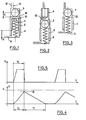
- the safety device for a constant pressure injection valve of an internal combustion engine shown in FIG. 1, comprises a ball 2 of diameter D resting on a hollow piston 4 quid by a sleeve 6 and recalled by an inner spring 8.
- This piston has a calibrated orifice with nozzle 10 of diameter d which connects the inlet 12 of the main pipe 14 supplying a non-electromagnetic control valve shown, at exit 16 of the safety device.
- the sleeve 6 is made of a metal that is relatively softer than the material of the ball 2 and the diameter D ′ for guiding the piston or internal diameter of the sleeve is slightly less than that D of the ball.
- the center of the ball 2 is separated from the edge 18 of the sleeve 6 by a maximum distance X + E ( ⁇ > 0), X representing the maximum displacement of this ball until contact with the sleeve 6.
- the piston is arranged above the ball itself raised by the return spring.
- FIG. 3 Another constructive arrangement illustrated in FIG. 3 can be adopted by leaving a clearance between the ball and the bore 20 in which it moves, such that the passage section thus defined is identical to that of the nozzle 10 represented in FIGS. 1 and 2.
- Figure 4 shows the movement of the ball 2 bearing on the piston 4, as a function of time. This movement and the injection rate shown in FIG. 5 are synchronized for a duration of time Ti.
- the return time of the ball under the effect of the return spring corresponds to Tr.
- the sum Ti + Tr is provided at a value slightly less than an injection period.
- the value X represents the maximum stroke of the ball, provided to allow the maximum amount of fuel to be injected, which causes the locking of the safety device.
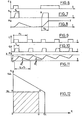
- Figures 6, 7 and 8 illustrate a case of exceeding the maximum amount injected resulting in safety.
- the second pulse of the control signal shown in Figure 6 for an electromagnetic valve is too long; the injection time Ti then reaches a fixed value Tm causing a maximum displacement X of the ball, which causes the safety device (cf. FIGS. 7 and 8).
- Figures 9, 10 and 11 illustrate a case of exceeding the engine speed resulting in safety.
- Figure 9 shows the periodic control signal of an electromagnetic valve.
- Figure 10 shows the quantity injected as a function of time.
- the period Pc of the control signal is less than the sum (Ti + Tr) representing the period specific to the safety device.
- the displacement of the ball increases by the value x.
- the device goes into safety (Xi represents the initial displacement of the ball and n the number of abnormal injections).
- FIG. 12 shows the overall operation of the safety device with the point Qi indicating the maximum quantity that can be injected, the point Ni indicating the start of the regression of the maximum flow rate as a function of the speed, the point Nm indicating the maximum speed that can theoretically be obtained with a very small amount injected.
- the engine operating limits must be limited to this trapezoid, for example the OQMN rectangle.
Landscapes
- Engineering & Computer Science (AREA)
- Chemical & Material Sciences (AREA)
- Combustion & Propulsion (AREA)
- Mechanical Engineering (AREA)
- General Engineering & Computer Science (AREA)
- Fuel-Injection Apparatus (AREA)
- Electrical Control Of Air Or Fuel Supplied To Internal-Combustion Engine (AREA)
Applications Claiming Priority (2)
| Application Number | Priority Date | Filing Date | Title |
|---|---|---|---|
| FR8400973 | 1984-01-23 | ||
| FR8400973A FR2558533B1 (fr) | 1984-01-23 | 1984-01-23 | Dispositif de securite pour soupape d'injection de moteur a combustion interne |
Publications (2)
| Publication Number | Publication Date |
|---|---|
| EP0150138A2 true EP0150138A2 (de) | 1985-07-31 |
| EP0150138A3 EP0150138A3 (de) | 1985-09-11 |
Family
ID=9300373
Family Applications (1)
| Application Number | Title | Priority Date | Filing Date |
|---|---|---|---|
| EP19850400023 Withdrawn EP0150138A3 (de) | 1984-01-23 | 1985-01-08 | Sicherheitsvorrichtung für Gleichdruckeinspritzventil einer Brennkraftmaschine |
Country Status (5)
| Country | Link |
|---|---|
| US (1) | US4589393A (de) |
| EP (1) | EP0150138A3 (de) |
| JP (1) | JPH0637865B2 (de) |
| ES (1) | ES8606578A1 (de) |
| FR (1) | FR2558533B1 (de) |
Cited By (2)
| Publication number | Priority date | Publication date | Assignee | Title |
|---|---|---|---|---|
| US5551403A (en) * | 1994-08-04 | 1996-09-03 | Mtu Motoren- Und Turbinen-Union Friedrichshafen Gmbh | Fuel supply quantity limiting arrangement |
| DE19747092A1 (de) * | 1997-10-24 | 1999-04-29 | Siemens Ag | Durchflußbegrenzungsvorrichtung für Brennkraftmaschinen |
Families Citing this family (12)
| Publication number | Priority date | Publication date | Assignee | Title |
|---|---|---|---|---|
| DE69218326T2 (de) * | 1991-01-14 | 1997-08-28 | Denso Corp | Druckakkumulier-kraftstoffeinspritzvorrichtung |
| DE4211651B4 (de) * | 1992-04-07 | 2004-11-18 | Robert Bosch Gmbh | Kraftstoffeinspritzeinrichtung, insbesondere Pumpedüse für Brennkraftmaschinen |
| US5412948A (en) * | 1992-10-23 | 1995-05-09 | Honda Giken Kogyo Kabushiki Kaisha | Hydrostatic continuously variable transmission |
| DE4414242A1 (de) * | 1994-04-23 | 1995-10-26 | Bosch Gmbh Robert | Kraftstoffeinspritzeinrichtung für Brennkraftmaschinen |
| DE29502829U1 (de) * | 1995-02-21 | 1996-06-20 | Robert Bosch Gmbh, 70469 Stuttgart | Kraftstoffeinspritzeinrichtung für Brennkraftmaschinen |
| JP3521811B2 (ja) | 1999-08-05 | 2004-04-26 | 株式会社デンソー | 内燃機関の安全装置 |
| FI114501B (fi) * | 2001-06-27 | 2004-10-29 | Waertsilae Finland Oy | Polttoainejärjestelmän virtausrajoitinventtiili |
| KR20060030116A (ko) * | 2003-07-17 | 2006-04-07 | 간제르-히드로막 아게 | 내연기관용 연료 분사 밸브 |
| JP2009544908A (ja) * | 2006-07-25 | 2009-12-17 | アロース ハイドラウリク ゲーエムベーハー | 油圧制御システム |
| US7658179B2 (en) * | 2008-05-28 | 2010-02-09 | Caterpillar Inc. | Fluid leak limiter |
| US7661410B1 (en) * | 2008-08-18 | 2010-02-16 | Caterpillar Inc. | Fluid leak limiter |
| US11346313B2 (en) * | 2020-09-03 | 2022-05-31 | Caterpillar Inc. | Fuel flow limiter assembly having integral fuel filter and fuel system using same |
Family Cites Families (11)
| Publication number | Priority date | Publication date | Assignee | Title |
|---|---|---|---|---|
| US2225175A (en) * | 1939-05-01 | 1940-12-17 | Charles A Koerner | Motor shutoff |
| US3583384A (en) * | 1969-07-01 | 1971-06-08 | Alden B Ranisate | Stove attachment |
| DE2103948A1 (de) * | 1971-01-28 | 1972-09-14 | Kupex Ag | Automatisches Ventil |
| ES177456Y (es) * | 1971-02-19 | 1973-03-01 | C. A. V. Limited | Disposicion de inyeccion de combustible. |
| US3845785A (en) * | 1971-04-26 | 1974-11-05 | Dover Corp | Spring biased safety valve |
| US3977430A (en) * | 1974-08-22 | 1976-08-31 | Bushee Joseph J | Ball check valve construction with pressure-responsive reset means |
| US4010770A (en) * | 1976-03-01 | 1977-03-08 | W-K-M Wellhead Systems, Inc. | Velocity flow control valve for fluid line |
| DE2754615A1 (de) * | 1977-12-08 | 1979-06-13 | Bosch Gmbh Robert | Absperrvorrichtung fuer mindestens ein einspritzventil fuer verbrennungsmotoren |
| JPS56173737U (de) * | 1980-05-26 | 1981-12-22 | ||
| JPS57105550A (en) * | 1980-12-19 | 1982-07-01 | Nissan Motor Co Ltd | Fuel injection pump for diesel engine |
| FR2502701A1 (fr) * | 1981-03-26 | 1982-10-01 | Renault Vehicules Ind | Systeme d'injection a pilotage de l'injecteur, pour un moteur a combustion interne |
-
1984
- 1984-01-23 FR FR8400973A patent/FR2558533B1/fr not_active Expired
-
1985
- 1985-01-08 EP EP19850400023 patent/EP0150138A3/de not_active Withdrawn
- 1985-01-16 US US06/691,886 patent/US4589393A/en not_active Expired - Lifetime
- 1985-01-22 ES ES539735A patent/ES8606578A1/es not_active Expired
- 1985-01-23 JP JP933185A patent/JPH0637865B2/ja not_active Expired - Lifetime
Cited By (3)
| Publication number | Priority date | Publication date | Assignee | Title |
|---|---|---|---|---|
| US5551403A (en) * | 1994-08-04 | 1996-09-03 | Mtu Motoren- Und Turbinen-Union Friedrichshafen Gmbh | Fuel supply quantity limiting arrangement |
| DE19747092A1 (de) * | 1997-10-24 | 1999-04-29 | Siemens Ag | Durchflußbegrenzungsvorrichtung für Brennkraftmaschinen |
| DE19747092B4 (de) * | 1997-10-24 | 2005-01-13 | Siemens Ag | Durchflußbegrenzungsvorrichtung für Brennkraftmaschinen |
Also Published As
| Publication number | Publication date |
|---|---|
| ES8606578A1 (es) | 1986-04-01 |
| JPH0637865B2 (ja) | 1994-05-18 |
| FR2558533A1 (fr) | 1985-07-26 |
| US4589393A (en) | 1986-05-20 |
| JPS60159366A (ja) | 1985-08-20 |
| FR2558533B1 (fr) | 1986-06-13 |
| EP0150138A3 (de) | 1985-09-11 |
| ES539735A0 (es) | 1986-04-01 |
Similar Documents
| Publication | Publication Date | Title |
|---|---|---|
| EP0119894A1 (de) | Elektromagnetisch gesteuertes druck-/zeitabhängiges Einspritzsystem für Dieselmotoren, in dem die Ventilnadel durch Entladen und Laden einer Kapazität geführt ist | |
| FR2593239A1 (fr) | Systeme d'injection de carburant pour moteur a combustion interne | |
| FR2558533A1 (fr) | Dispositif de securite pour soupape d'injection de moteur a combustion interne | |
| FR2759740A1 (fr) | Dispositif d'injection a accumulateur pour moteurs a combustion interne multicylindriques | |
| FR2571438A1 (fr) | Injecteur de combustible du type a accumulation | |
| FR2486158A1 (fr) | Dispositif d'alimentation en combustible d'un moteur a allumage par compression | |
| FR2742190A1 (fr) | Injecteur de carburant pour moteurs a combustion interne | |
| FR2466630A1 (fr) | Injecteur a actionnement electromagnetique, pour moteurs a combustion interne | |
| FR2786225A1 (fr) | Systeme d'injection de carburant sous haute pression dans un moteur a combustion interne a injection directe | |
| FR2759736A1 (fr) | Unite de commande d'un systeme d'injection pour un moteur a combustion interne a plusieurs cylindres | |
| EP0898649B1 (de) | Flüssigkraftstoffeinspritzvorrichtung für verbrennungsmotor | |
| FR2529950A1 (fr) | Appareil de refroidissement de l'air de combustion de moteurs a combustion interne | |
| FR2741673A1 (fr) | Dispositif de decharge rapide pour arreter brusquement l'injection dans un injecteur hydraulique de carburant | |
| FR2539818A1 (fr) | Injecteur de carburant | |
| FR2524564A1 (fr) | Pompe d'injection de carburant | |
| EP0278814B1 (de) | Kraftstoffregler für Turbomaschinen | |
| FR2508548A1 (fr) | Dispositif pour limiter le debit d'injection de combustible dans un moteur diesel | |
| EP1463887B1 (de) | Startsystem für verbrennungsmotor | |
| FR3022002A1 (fr) | Procede de commande d'injections multiples notamment dans un systeme d'injection de carburant d'un moteur a combustion interne | |
| FR2811379A1 (fr) | Injecteur de craburant avec un element de commande de pression | |
| EP0585171A1 (de) | Flüssigkraftstoffeinspritzvorrichtung für einen Verbrennungsmotor und mit einer solchen Vorrichtung ausgestatteter Motor | |
| FR2790301A1 (fr) | Soupape a section de passage variable | |
| FR2534631A1 (fr) | Injecteur de carburant | |
| FR2773593A1 (fr) | Systeme d'injection de carburant pour moteurs a combustion interne | |
| WO1998025026A1 (fr) | Dispositif de ralentissement d'ouverture et de reduction de fuite pour systemes d'injection a pression constante utilises sur moteurs diesel |
Legal Events
| Date | Code | Title | Description |
|---|---|---|---|
| PUAI | Public reference made under article 153(3) epc to a published international application that has entered the european phase |
Free format text: ORIGINAL CODE: 0009012 |
|
| PUAL | Search report despatched |
Free format text: ORIGINAL CODE: 0009013 |
|
| 17P | Request for examination filed |
Effective date: 19850111 |
|
| AK | Designated contracting states |
Designated state(s): BE DE GB IT NL SE |
|
| AK | Designated contracting states |
Designated state(s): BE DE GB IT NL SE |
|
| 17Q | First examination report despatched |
Effective date: 19860521 |
|
| STAA | Information on the status of an ep patent application or granted ep patent |
Free format text: STATUS: THE APPLICATION IS DEEMED TO BE WITHDRAWN |
|
| 18D | Application deemed to be withdrawn |
Effective date: 19861001 |
|
| RIN1 | Information on inventor provided before grant (corrected) |
Inventor name: MIETTAUX, MARC Inventor name: JOURDE, JEAN-PIERRE |