EP0153079A1 - Gewindefeder-Fliehkraftkupplung - Google Patents
Gewindefeder-Fliehkraftkupplung Download PDFInfo
- Publication number
- EP0153079A1 EP0153079A1 EP85300751A EP85300751A EP0153079A1 EP 0153079 A1 EP0153079 A1 EP 0153079A1 EP 85300751 A EP85300751 A EP 85300751A EP 85300751 A EP85300751 A EP 85300751A EP 0153079 A1 EP0153079 A1 EP 0153079A1
- Authority
- EP
- European Patent Office
- Prior art keywords
- springs
- spring
- coils
- clutch
- further characterized
- Prior art date
- Legal status (The legal status is an assumption and is not a legal conclusion. Google has not performed a legal analysis and makes no representation as to the accuracy of the status listed.)
- Withdrawn
Links
- 230000000694 effects Effects 0.000 claims abstract description 43
- 230000036316 preload Effects 0.000 claims description 13
- 230000007246 mechanism Effects 0.000 claims description 7
- 238000004804 winding Methods 0.000 claims description 4
- 230000009471 action Effects 0.000 claims description 3
- 230000004044 response Effects 0.000 claims description 3
- 238000000034 method Methods 0.000 claims 4
- 239000000463 material Substances 0.000 description 22
- 230000007423 decrease Effects 0.000 description 13
- 230000004323 axial length Effects 0.000 description 9
- 230000008901 benefit Effects 0.000 description 5
- 230000008859 change Effects 0.000 description 5
- 229910000831 Steel Inorganic materials 0.000 description 4
- 238000009826 distribution Methods 0.000 description 4
- 239000012530 fluid Substances 0.000 description 4
- 235000019589 hardness Nutrition 0.000 description 4
- 239000010959 steel Substances 0.000 description 4
- 230000001052 transient effect Effects 0.000 description 4
- 229910000906 Bronze Inorganic materials 0.000 description 3
- 229910000975 Carbon steel Inorganic materials 0.000 description 3
- 238000013459 approach Methods 0.000 description 3
- 239000010974 bronze Substances 0.000 description 3
- 239000010962 carbon steel Substances 0.000 description 3
- KUNSUQLRTQLHQQ-UHFFFAOYSA-N copper tin Chemical compound [Cu].[Sn] KUNSUQLRTQLHQQ-UHFFFAOYSA-N 0.000 description 3
- 238000004519 manufacturing process Methods 0.000 description 3
- 230000009467 reduction Effects 0.000 description 3
- 230000003321 amplification Effects 0.000 description 2
- 230000003247 decreasing effect Effects 0.000 description 2
- 238000003754 machining Methods 0.000 description 2
- 230000013011 mating Effects 0.000 description 2
- 239000002184 metal Substances 0.000 description 2
- 229910052751 metal Inorganic materials 0.000 description 2
- 150000002739 metals Chemical class 0.000 description 2
- 238000003199 nucleic acid amplification method Methods 0.000 description 2
- 239000007858 starting material Substances 0.000 description 2
- 238000003466 welding Methods 0.000 description 2
- 229910000851 Alloy steel Inorganic materials 0.000 description 1
- 229910000760 Hardened steel Inorganic materials 0.000 description 1
- 230000001133 acceleration Effects 0.000 description 1
- 230000015556 catabolic process Effects 0.000 description 1
- 230000006835 compression Effects 0.000 description 1
- 238000007906 compression Methods 0.000 description 1
- 230000008602 contraction Effects 0.000 description 1
- 238000010168 coupling process Methods 0.000 description 1
- 238000005859 coupling reaction Methods 0.000 description 1
- 238000006731 degradation reaction Methods 0.000 description 1
- 239000000314 lubricant Substances 0.000 description 1
- 238000005461 lubrication Methods 0.000 description 1
- 238000004901 spalling Methods 0.000 description 1
Images
Classifications
-
- F—MECHANICAL ENGINEERING; LIGHTING; HEATING; WEAPONS; BLASTING
- F16—ENGINEERING ELEMENTS AND UNITS; GENERAL MEASURES FOR PRODUCING AND MAINTAINING EFFECTIVE FUNCTIONING OF MACHINES OR INSTALLATIONS; THERMAL INSULATION IN GENERAL
- F16D—COUPLINGS FOR TRANSMITTING ROTATION; CLUTCHES; BRAKES
- F16D43/00—Automatic clutches
- F16D43/02—Automatic clutches actuated entirely mechanically
- F16D43/04—Automatic clutches actuated entirely mechanically controlled by angular speed
- F16D43/14—Automatic clutches actuated entirely mechanically controlled by angular speed with centrifugal masses actuating the clutching members directly in a direction which has at least a radial component; with centrifugal masses themselves being the clutching members
- F16D43/18—Automatic clutches actuated entirely mechanically controlled by angular speed with centrifugal masses actuating the clutching members directly in a direction which has at least a radial component; with centrifugal masses themselves being the clutching members with friction clutching members
Definitions
- This invention relates to the field of clutches, and more particularly to clutches utilizing a coil spring as a clutch element.
- Conventional clutches typically engage or disengage over a narrow speed range, measured in revolutions- per minute (RPM). They tend to suddenly apply a load when the clutch member engages or disengages, which can be harmful to the system components.
- RPM revolutions- per minute
- One object of this invention is to provide a smooth clutch engagement over a relatively broad RPM range.
- Another object of this invention is to provide a clutch which does not require a fluid bath for operation.
- the invention comprises a clutch having first and second members mounted for rotation relative to each other.
- a plurality of interconnected capstan spring coils are concentrically positioned with respect to a cylindrical surface on one of the members.
- the spring coils are connected to be rotated by an inner input member.
- the cylindrical surface is on an outer, output member adjacent to the outer diameter of the spring coils, with a predetermined gap initially separating the spring coils and the surrounding surfaee.
- the rotational velocity . of the input member increases the centrifugal expansion of the spring coils, the outer surfaces of the spring coils begin to frictionally engage the surrounding surface acting as a clutch. If the coils are rotating faster than the outer member, this engagement produces an unwinding force on the spring coils which increases the engagement, thus improving. the efficiency of the torque transfer.
- the . spring connection to the input member permits the spring coils to expand outward in a radial direction.
- the clutch is used in a starter by having the centrifugal expansion of the spring coils disengage an input member. This occurs when the spring coils are connected to rotate the output member and the springs are preloaded onto a cylindrical surface on the input member. As the input member begins rotating, the preload between the spring coils and the input member causes rotation of the output member. The inertia of the output member tends to produce a winding force on the spring coils about the input member, providing a capstan effect which increases the load transfer efficiency.
- the centrifugal force decreases, and the spring coils contract until they re-engage the inner member. If the inner member is at that stage rotating faster than the outer member, the spring coils will smoothly grip the inner member so that the outer member will be once more driven. However, if the inner member is moving slowly or not moving, as in a typical starter situation, the spring coils merely slide on the inner member in an overrunning condition in that the outer member will be providing a spring unwinding torque.
- the geometry of the springs is varied in order to minimize the axial length of the spring while providing an increased amount of spring material where the spring stresses are highest.
- the spring coils nearest the connection point or anchor point are axially thicker than the remaining coils since the loads are greatest nearest the anchor point.
- the spring coil axial thickness can vary along the axial length of the spring in a number of ways depending upon the design requirements and manufacturing capabilities. Ideally, the spring coil axial thickness would be greatest immediately adjacent the anchor point and decrease in a logarithmic manner towards the free end of the spring. From a practical viewpoint, the spring cvil axial thickness will decrease in a linear manner from a maximum at the spring coil immediately adjacent the anchor point, to some point along the length of the spring after which the thickness would be constant.
- the increase in spring coil axial thickness immediately adjacent the anchor point does cause an increase in the torque required to back drive the, spring. If desired, this increase can' be reduced by the tapering diameter of the spring slightly along the axial length of the first few coils immediately adjacent the anchor point so as to reduce the impact of those first few coils on the back drive effect.
- the radial spring dimension is varied to alter the back drive affect by varying the clearance or preload.
- variable axial thickness springs not only better accommodates the load distribution during operation of the clutch, but also allows the use of materials which were previously not usable because of the high stresses exerted on the springs.
- the use of these materials improves the spring life and the clutch operation, and reduces the -galling and cold weld problems associated in previous designs. The result is a much more compact, long-life clutch which can operate at higher torques, and over a broader speed range, than previously available.
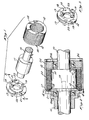
- coil springs 12 and 14 are concentrically interlaced.
- the springs 12 and 14 are identical, each having a plurality of turns or coils N (not labeled), 'with the same diameter and with a space between each adjacent coil sufficient to accommodate the coil of the other interlaced spring.
- coil springs 12 and 14 are formed with a right-handed helix.
- the cross-sectional shape of coil springs 12 and 14 is shown as rectangular, although numerous cross-sectional shapes would also work. The rectangular shape, with the long axis radially orientated, provides a high resistance to centrifugal expansion which enables the spring-clutch feature to operate at high rotational velocities.
- This orientation also allows a large number of springs 12 and 14 to be interlaced, so a sufficient numbers of coils for capstan action can be packed into a limited space.
- Different spring cross sections can accommodate different operational speeds in a more efficient manner by tailoring the spring stiffness parameters accordingly.
- Coil springs 12 and 14 are coaxial with an inner member, such as input shaft or member 10, being positioned over a shaft section 11 of stepped-up diameter.
- the selected diameter directly affects the centrifugal force exerted on the springs 12 and 14; the larger the diameter of shaft section 11, the larger the centrifugal force expanding the springs 12 and 14.
- each coil spring 12 and 14 is connected to input shaft 10 through an annular connecting plate 17.
- Pins 18 are anchored in one end of coil springs 12 and 14 and are loosely positioned in holes 21 in the connecting plate 17.
- Connecting plate 17, in turn, is fastened to input shaft 10 by pins 19, or other suitable fasteners.
- the plate 17 includes a pair of diametrically spaced, axially extending projections 23, as seen in FIG. 3.
- the pinned end of each spring 12 and 14 is adjacent a projection 23 such that rotation of end plate 17 in the direction of the arrow in FIGS. 1 and 3 results in projections 23 abutting against the pinned ends of the coil springs 12 and 14 causing them to rotate in that direction.
- Holes 21 allow the ends of springs 12 and 14 to move, especially in the radial direction as the springs 12 and 14 expand or contract under centrifugal force.
- An outer member such as output shaft or member 16.is positioned coaxial with input shaft 10 and has a portion 22a, containing a cylindrical engaging surface 22 which surrounds and is slightly separated from the outer surface of coil springs 12 and 14 when the springs are not rotating.
- suitable bearings 20a " and 20b allow output shaft 16 to freely rotate about input shaft 10.
- An annular bearing ring support 24 holds bearing 20b in position and separates the ends of springs . 12 and 14 from bearings 20b to prevent rubbing.
- Snap ring 26 in turn retains the bearing support 24. Numerous support configurations are possible which would allow free rotation of output shaft 16 with respect to input shaft 10.
- the coil springs 12 and 14 be preloaded onto section 11 of input shaft 10.
- the diameter of coil springs 12 and 14 in the free, unstressed condition is smaller than the stepped-up diameter of section 11.
- this preload or pre-interference serves to minimize rattling and transient vibration and stresses which would occur in the coil springs. 12 and 14 for transient torsional loads which accompany sudden changes in the rotation velocity of input shaft 10. Such transient vibrations and loads could damage the coil springs 12 and 14.
- the end plate projections 23 cause coil springs 12 and 14 to rotate with the shaft. That is, the projections 23 push on the circumferentially facing ends of the springs 12 and 14, as seen in FIG. 3. Any preload or pre-interference between springs 12 and 14 and shaft section 11 also helps impart rotation to the springs 12 and 14. As rotational velocity increases, a centrifugal force is exerted on coil springs 12 and 14, which force tends to expand the diameter of the springs. This expansion reduces the preload, if any, between the coils of springs 12 and 14 and the shaft section 11. Such expansion also closes the gap which previously existed between the outer surfaces of coil springs 12 and 14, and the surrounding cylindrical surface 22 of output member 16.
- coil springs 12 and 14 expand to contact or engage the engaging surface 22 on cylindrical portion 22a, thereby imparting a velocity to output shaft 16.
- the . centrifugal expansion and contraction of coil springs 12 and 14 thus acts as a clutch.
- the springs 12 and 14 in this embodiment thus move from a disengaged to an engaged position with cylindrical surface 22 as the spring rotational velocity is increasing.
- a sliding contact occurs between the outer surface of coil springs 12 and 14 and cylindrical surface 22 when'the springs first contact the surface 22.
- This sliding contact contributes to a gradual engagement of the input shaft 10 with the output shaft 16 through the coil springs 12 and 14.
- This gradual connection of output shaft 16 with input shaft 10 exists because the centrifugal expansion of coil springs 12 and 14 occurs gradually as the rotational velocity of input shaft 10 increases. Assuming the output member 16 is not rotating, or is rotating in the direction of the arrow of FIG.
- the range of speeds over which input shaft 10 is coupled to output shaft 16 depends upon several controllable factors. Correct selection and combination of these factors allows a clutch effect to .occur at desired speed, or over a desired range of speeds.
- One factor is the gap or distance between the outer surface of coil springs 12 and 14, and the engaging surface 22 of . output shaft 16.
- the amount of preload between the coil springs 12 and 14 and the input shaft 10 affects the speed at which the coil springs 12 and 14 begin to expand from the input shaft 10.
- the shape of the cross section of each coil of coil springs 12 and 14 is also important, as it affects the spring stiffness and the spring_'s resistance to expansion by centrifugal forces.
- the dimension of the stepped-up diameter 11 also affects the expansion of the coil springs 12 and 14, since the centrifugal force is a function of the radius from the center line of rotation.
- FIGS. 1-4 The form of the invention illustrated in FIGS. 1-4 is particularly useful in transmitting additional torque to an already rotating load.
- a gas turbine is commonly used to drive a load at a certain speed. Residual heat from the turbine is used to generate steam to rotate a steam turbine to be used as a booster, if the load should increase.
- the clutch in FIG. 1 may be used to connect the steam turbine output to the load. That is, the clutch inner shaft 10 is connected to be rotated by the steam turbine, and the outer shaft 16 is connected to the load. As the steam turbine accelerates, the clutch automatically, and smoothly transmits torque to the outer shaft 16, and hence, to the load, at a predetermined speed. If the booster is no longer needed so that the steam turbine speed is reduced, the clutch smoothly disconnects the input and output members at the predetermined speed.
- the mechanism shown in FIG. 2 can transmit 2,000 horsepower at an operational speed of 8,000 RPM.
- the input shaft section 11 has a stepped up diameter of 2.5 inches.
- Two steel coil springs 12 and 14 are used in an interlaced fashion, each spring having a rectangular cross section of .1 x .5 inches, and having 8 coils.
- the clutch effect begins at a high speed, about 4800 RPM, and the springs 12 and 14 are fully engaged to output shaft 16 at 6400 RPM. Thus the clutch engages gradually between 60% and 80% of the operation speed of 8000 RPM.
- the unrestrained, inner diameter of springs 12 and 14 is preferably a few thousandths of an inch less than the outer diameter of the shaft section 11; and the gap between the spring outer diameter, when on the section 11, and the inner diameter of the cylindrical engaging surface 22 is also a few thousandths of an inch. These factors are related.
- the difference between the unrestrained, outer diameter of springs 12 and 14, and the inner diameter of the surface 22 in this one form of the invention is about 15 thousandths of an inch.
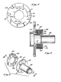
- FIGS. 5 and 6 a pair of coil springs 32 and 34 are fastened to an output shaft member 36.
- This embodiment is suitable for high-torque uses, such as for starting an engine connected to the shaft 36.
- An inner input shaft member 30 (FIG. 5) is coaxial with the output shaft 36.
- Coils N (not labeled) on springs 32 and 34 are intertwined and preloaded onto an engaging surface, such as the cylindrical surface 31a on a hub 31 (FIG. 5) of the input shaft 30.
- Rectangular lugs 40 on the springs 32 and 34 connect one end of each coil spring 32 and 34 to a flange 39 on the output shaft 36. More specifically, the lugs 40 fit within mating rectangular recesses 41 formed in the flange 39. The connection is loose and the lugs 40 and recesses 41 are oriented so that the lugs 40 and the ends of springs 32 and 34 can move radially.
- a housing 42 (FIG. 5) encloses the springs 32 and 34 and the flange 40.
- a snap ring 38 (FIG. 5) fixes the axial position of helical springs 32 and 34 within the housing 42.
- input shaft 30 and output shaft 36 are coaxial and connected only by the helical springs 32 and 34.
- the preload between the inner surface of coil springs 32 and 34, and the outer cylindrical surface 31a of output shaft 30, serves to connect the input shaft 30 to the output shaft 36 through the lugs 40.
- the load of output shaft 36 received by the springs 32 and 34 through the lugs 40, resists rotation, producing tension in the springs 32 and 34 which produces a winding action on the coil springs 32 and 34. That is, the helical coil springs 32 and 34 are placed in tension by a counterclockwise rotation of input shaft 30, as shown in FIG. 6, with the result that the springs 32 and 34 are urged to contract and grip input shaft 30 even tighter in a capstan effect, thus increasing the load transfer efficiency from the input shaft 30 to the output shaft 36.
- the gripping force is reduced by the centrifugal expansion of the springs 32 and 34.
- the centrifugal force exerted on coil springs 32 and 34, and an unwinding force on the spring produced by the output shaft 36 causes the springs 32 and 34 to disengage contact with input shaft 30. That is, the flange 39 and its recesses 41 push on the spring lugs '40 placing the springs 32 and 34 in compression.
- the springs 32 and 34 in this embodiment thus move from an engaged to a disengaged position with respect to the cylindrical surface 31a of the input shaft 30. Also, the springs 32 and 34 permit overrunning, wherein the- output shaft 36 goes faster than the input shaft 30.
- the coil springs 32 and 34 will re-engage contact with the input shaft 30. If the input shaft 30 is still rotating, the capstan effect also operates during the re-engagement to once more effectively couple the two rotating shafts 30 and 36 in an efficient driving manner. However, if the input shaft 30 is not rotating, the unwinding force on the springs 32 and 34 produced by the output shaft 36 permits overrunning.
- the range over which the clutch effectively disengages by disengaging coil springs 32 and 34 from contact with input shaft 30, can be varied by controlling the amount of preload between the coil springs 32 and 34 and input shaft 30. Varying the cross-sectional shape of the coils of coil springs 32 and 34 also affects the clutch actuation by determining the resistance of springs 32 and 34 to centrifugal expansion.
- coil springs having a cross section of approximately .0625 x .5 inches it is possible to deliver at least 600 foot pounds of torque at zero RPM without degradation, and up to 1,000 foot pounds without slipping or structural failure. Although the deliverable torque decreases as the speed increases, it is still possible to deliver at least 300 foot pounds at 11,000 RPM.
- Complete disengagement of coil springs 32 and 34 from the input shaft 30 can be designed to occur between 11,000 and 20,000 RPM.
- the absence of fluids for lubrication and force transfer allows the clutch to operate relatively unaffected by temperatures in the range of -65 to 350 degrees Fahrenheit and under any pressure conditions.
- interlaced coil springs 12 and 14, or 32 and 34 allows this clutch to operate at high rotational velocities, from a few thousand RPM, to rotational speeds over 20,000 RPM.
- Using two interlaced coil springs such as springs 12 and 14 allows the springs to be installed symmetrically and to retain that symmetrical weight distribution during operation at both low and high rotational speeds.
- both ends of the springs 12 and 14 are spaced 180° apart. This relationship stays the same as the coils expand. More than two coil springs can be used, so long as the springs are symmetrically positioned and designed to expand symmetrically under centrifugal forces.
- the spacing between the individual spring coils such as spring 12, to accommodate coils of an additional spring such as spring 14, also makes it easier to machine the springs 12 and 14, and still keep close fitting tolerances, thereby reducing manufacturing costs, while obtaining compactness.
- the absence of fluids or lubricants also enables the clutch to operate over a wide temperature range.
- the high load transfer efficiency of the capstan effect results in a relatively low weight clutch assembly compared to the torque which can be transmitted.
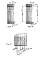
- FIGS. 7 and 8 show an alternate embodiment of the coil springs 12, 13, 32, and 34, suitable-for use in the above inventions.
- two coil springs 52 and 54 are again interleaved or intertwined as previously described.
- the geometry of the coil springs 52 and 54 varies in that the axial thickness t of each coil decreases at a constant rate, along the length of the helix of the coil springs 52 and 54.
- the ends of the coil springs 52 and 54 which are attached or anchored to the connecting plate 17 (FIG. 3) or the flange 39 (FIG. 6), are the thickest, while the free end of the coil springs 52 and 54 are the thinnest, in axial thickness t.
- the inner diameter of the coil springs 52 and 54 is constant.
- FIG. 8 has a more pronounced variation in geometry than the embodiment of the invention shown in FIG. 7.
- FIG. 8 shows two, interleaved, coil springs 62 and 64, each having a lug 60, comparable to the lugs 40 as described in the embodiment shown in FIG. 6. ' Still referring to FIG. 8, the lugs 60 cooperate with an anchor point such as flange 39 (FIG. 6) to connect or anchor one end of the coil springs 62 and 64 to an input or output device (not shown).
- the thickness t of the individual coils on the coil springs 62 and 64 varies along the axial length of the coil springs 62 and 64.
- the initial axial thickness t of the rectangular cross-section of the coil springs 62 and 64 is approximately .120 inches at the end of the first coil N1.
- the axial thickness t initially decreases at a uniform or constant rate along the helix of the coil springs 62 and 64, until, after approximately three turns, the axial thickest of the'third coil N3 is reduced to about .030 inches, or roughly 1/4 of the initial thickness.
- the axial thickness t remains constant for the remaining six coils of the coil springs 62 and 64 in the specific embodiment illustrated in FIGS. 8 and 9.
- the outer diameter of the coil springs 62 and 64 is approximately 3.784 inches, with a dimensional tolerance of +.002, and -.001 inches. This taper can be thought of as a variable radial width h in springs 62 and 64.
- the inner diameter of the coil springs 62 and 64 is not constant, but rather has a taper at one end. The inner diameter is constant at 2.984 inches for half the length of the spring and has a dimensional tolerance of +.000 inches and -.002 inches throughout the length of the coil springs 62 and 64.
- the half of the coil springs 62 and 64 adjacent the lugs 60 taper radially outward to a larger inner diameter of 3.000 inches, at the lugs 60.
- the axial. length of the intertwined coil springs 62 and 64 is approximately .885 inches, neglecting the machining gaps between the individual coils of coil springs 62 and 64.
- the coil springs 62 and 64 have a variable geometry in which the coils are axially thickest at the anchor point and taper in a predefined manner towards the free end of the springs 62 and 64.
- The-inner diameter or radial width h of the coil springs 62 and 64 may also be varied in a predetermined manner.
- the first coil N1 In a capstan spring having a number of coils N, the first coil N1 carries a disproportionate amount of the load. It is believed that the first coil N1 carries approximately one-half of the entire load transmitted by the capstan spring. Thus, it is desirable to have the first coil N1 be the largest to carry this disproportionate load. Conversely, the spring coils carrying less load do not need to be as large.
- the increase in spring size can be achieved by varying either, or both, the axial thickness t or the radial width h of the spring.
- the centrifugal expansion effect of the capstan springs 52 and 54 does not vary as the coil's 'axial thickness t is changed, but does vary as the radial width h is changed. Radial expansion from centrifugal acceleration depends upon the stiffness of the capstan springs 62 and 64, which stiffness increases exponentially with an increase in the radial width h of the coil springs. The centrifugal expansion does not vary with a - change in the axial thickness t since the centrifugal force is directly proportional to both the mass and the stiffness of the coils, but in opposite ways. The mass, in turn, is linearly proportional to the axial thickness t.
- any change in axial thickness t causes the effect of the change in stiffness to be canceled by the effect of the change in mass so the centrifugal force remains unchanged.
- the axial thickness t is varied to accommodate the spring stresses, rather than varying the radial width h of the coil springs 62 and 64.
- the first coil N1 of the coil springs 62 and 64 carries approximately one-half of the load, with the load in the remaining coils decreasing in a non-linear manner.
- the load carried by the individual coils of the coil springs 62 and 64 is believed to decrease as a function of the natural log of the axial length from the anchored end of the coil springs 62 and 64. From a practical viewpoint, this explanation means that the first few coils of the capstan spring 62 and 64 carry the majority of the load, while the last few coils conceivably carry little load, but are needed to provide the appropriate amplification of the capstan effect.
- FIGS. 7 and 8 accommodate this variable load by increasing the axial thickness t of the first coils near the anchor point on the capstan springs 52, 54, 62, and 64, while decreasing the axial thickness t on the last coils which are furthest from the anchor point.
- the first coil N1 on capstan springs 52 and 54 has an initial axial thickness t of 0.120 inches. This axial thickness t decreases linearly to thicknesses of .090 inches, .060 inches, and .030 inches in a uniform manner after .One (N2), two (N2), and three (N3) complete coils, respectively. The remaining coils are of a constant axial thickness t.
- the variation in coil axial thickness t is linear (.030 inches per coil N) whereas it is believed the load in the coils decreases in a non-linear manner. While it would be preferable from a theoretical design viewpoint to vary the coil axial thickness t in the same relationship as the load varies, it is believed that the linear variation in axial thickness t can be more economically manufactured and yet adequately accommodates the load variation. Simply put, at the present, its cheaper to cut a linear variation on the axial thickness t of the coils than it is to cut a non-linear, axial thickness t.
- the above explanation and design is based primarily on accommodating stress, rather than on accommodating stiffness. There are, however, other factors which do influence the design, these being the capstan effect and the back drive effect.
- the capstan effect which causes an increased gripping and load transfer efficiency varies along the length of the coil springs 52, 54, 62, and 64.
- the capstan effect increases as the distance from the anchor point (such as lug 60) increases.
- the result is that the end coils have a much larger amplification or capstan effect than do the coils immediately adjacent the anchor point (such as lugs 60).
- the designs shown in the embodiments of FIGS. 7 and 8 are believed to provide sufficient material on the end coils of the capstan springs 52, 54, 62, and 64 so that those coils are not over stressed by any operational loads which are exerted or amplified by the capstan effect.
- the back drive effect refers to the torque which is required to expand or open the spring coils N on the capstan springs 52, 54, 62, and 64 in order to allow sliding of a shaft gripped by the inside of those capstan springs.
- the back drive effect is significant if there is a preload or pre-interference between the capstan springs 52, 54, 62, and 64 and one of the shafts, such as shaft section 11 (FIG. 1).
- the back drive effect varies as a function of the axial thickness t of the capstan springs 62 and 64.
- the back drive effect is also non-linear and decreases in a non-linear manner from a maximum effect at the coil N1 immediately adjacent the anchor point, to a minimum value towards the free end of the coil springs 62 and 64.
- the back drive effect of each coil N is believed to vary in an exponential manner, and specifically it is believed to vary proportional to the inverse log of the distance of the coil N from the anchor point.
- the greatest impact on the back drive effect is caused by axial thickness t of the first few coils immediately adjacent to the anchor point.
- the increased axial thickness t of the coil springs 62 and 64, to accommodate the operational loads causes an undesirable increase in the back drive effect.
- increasing the axial thickness t to accommodate higher loads also increases the back drive effect, which has the undesirable result of requiring more torque on the shaft which is grasped by the capstan effect in order to allow slippage - of that shaft in the back drive condition.
- FIG. 8 shows (exaggerated for illustration) the inner diameter of the capstan springs 62 and 64 to have a taper which decreases from a maximum value at the anchor point of lugs 60, to a smaller diameter at approximately one-half of the axial length of the coil springs 62 and 64.
- the ideal variation of the taper to counter the back drive effect would be a non-linear change in the inner diameter of the capstan springs 62 and 64, with that inner diameter varying in the same non-linear manner in which the back drive effecfvaries along the length of the capstan springs 62 and 64.
- the linear variation shown in FIG. 8 is believed suitable to counter the back drive effect, yet is much easier to machine on existing equipment.
- capstan effect is the greatest on the coils at the free end of the capstan springs 62 and 64, it is desirable to have those end coils have the proper internal diameter to insure that the correct drag (if any) on the gripped shaft exists. If the gripped shaft is on the outer diameter, rather than the inner diameter of the capstan spring 62 and 64, then the corresponding taper to counter the back drive effect would be on the external - diameter of the springs, rather than on the internal diameter as illustrated in FIG. 8 and as described above.
- Varying the axial thickness t of the capstan spring coils such as 62 and 64 produces several unexpected advantages.
- the design allows a reduction in the weight and in axial length of the capstan springs 62 and 64. This length reduction can be very important in situations where the space for the clutch is very limited.
- the design allows the use of spring materials which could not previously be used. In prior designs, the entire spring was designed to accommodate the maximum stress with the result that high strength materials were required to prevent fracture while reducing the spring cross section in order to reduce weight and length. Since the spring cross section is now varied to better accommodate the stress or load distribution in the spring, softer materials can be used.
- unalloyed carbon steel such as 1045 steel can be used, although it is possible that spring materials such as phospher bronze could also be used. These materials were not previously able to be used in the high load, high speed designs described above.
- spring materials such as phospher bronze could also be used.
- FIG. 8 using unalloyed carbon steel springs with a radial width of .4 inches, can transmit 1200 ft. lbs. of torque at zero RPM, with the clutch operating in the speed range of 4950 to 5050 rpm, and with a diametrical pre-interference of 0.016 inches.
- a still further advantage is the reduction in cold weld, galling, and spalling which typically occurs when two similar, hard metals rub together.
- Previous designs require the use of very high strength, and thus very hard materials in order to prevent fracture of the capstan springs during operational or transient. loading conditions.
- the tendency to gall or cold weld increases as the hardness of the contacting materials is increased. This galling tendency also increases when the.- contacting materials are similar.
- a hard capstan spring rubbing against a hard engaging surface both of similar materials, would be likely to gall, whereas the use of a different and softer material such as a softer, steel or phospher bronze spring rubbing against the same hard engaging surface, would be far less likely to gall or cold weld.
- the tendency to gall is reduced if the contacting metals are very dissimilar.
- a steel capstan spring rubbing against an engaging surface made of a the same steel alloy is much more likely to gall than is a capstan spring made of a dissimilar material such as phospher bronze or unalloyed carbon steel which would rub against the same hardened steel engaging surface.
- This design allows the use of dissimilar materials of different hardnesses, thus reducing the tendency to gall or cold weld.
Landscapes
- Engineering & Computer Science (AREA)
- General Engineering & Computer Science (AREA)
- Mechanical Engineering (AREA)
- One-Way And Automatic Clutches, And Combinations Of Different Clutches (AREA)
Applications Claiming Priority (4)
| Application Number | Priority Date | Filing Date | Title |
|---|---|---|---|
| US57926784A | 1984-02-13 | 1984-02-13 | |
| US579267 | 1984-02-13 | ||
| US69004885A | 1985-01-09 | 1985-01-09 | |
| US690048 | 1985-01-09 |
Publications (1)
| Publication Number | Publication Date |
|---|---|
| EP0153079A1 true EP0153079A1 (de) | 1985-08-28 |
Family
ID=27077716
Family Applications (1)
| Application Number | Title | Priority Date | Filing Date |
|---|---|---|---|
| EP85300751A Withdrawn EP0153079A1 (de) | 1984-02-13 | 1985-02-05 | Gewindefeder-Fliehkraftkupplung |
Country Status (1)
| Country | Link |
|---|---|
| EP (1) | EP0153079A1 (de) |
Cited By (8)
| Publication number | Priority date | Publication date | Assignee | Title |
|---|---|---|---|---|
| WO2001004506A1 (en) * | 1999-07-13 | 2001-01-18 | Yue Wang | Automatic clutch |
| GB2377259A (en) * | 2001-06-13 | 2003-01-08 | Hiflux Plc | Connecting apparatus |
| US9703312B2 (en) | 2015-09-29 | 2017-07-11 | Moog Inc. | Non-jamming stop module for high revolution applications |
| WO2021226633A1 (en) | 2020-05-06 | 2021-11-11 | Baker Hughes Oilfield Operations Llc | Motor drive shaft spring clutch in electrical submersible pump |
| US11773857B2 (en) | 2018-10-12 | 2023-10-03 | Baker Hughes Holdings Llc | Dual ESP with selectable pumps |
| WO2024025838A1 (en) | 2022-07-27 | 2024-02-01 | Baker Hughes Oilfield Operations Llc | Motor drive shaft spring clutch in electrical submersible pump |
| US12038013B2 (en) | 2020-05-06 | 2024-07-16 | Baker Hughes Oilfield Operations, Llc | Motor drive shaft spring clutch in electrical submersible pump |
| US12553320B2 (en) | 2021-09-03 | 2026-02-17 | Baker Hughes Oilfield Operations Llc | Auto-engageable coupling for preventing transmission of reverse rotation to ESP motors |
Citations (10)
| Publication number | Priority date | Publication date | Assignee | Title |
|---|---|---|---|---|
| DE232537C (de) * | ||||
| FR563506A (fr) * | 1922-05-29 | 1923-12-07 | Poulie de transmission à embrayage instantané | |
| FR755112A (fr) * | 1933-05-03 | 1933-11-20 | Mécanisme d'embrayage | |
| US1972915A (en) * | 1931-10-12 | 1934-09-11 | Lgs Devices Corp | Spring clutch |
| FR995834A (fr) * | 1949-09-19 | 1951-12-10 | Poulie de démarrage automatique à spiral de friction | |
| DE915165C (de) * | 1944-03-29 | 1954-07-15 | Erich Schmettow | Schraubenband-Reibungskupplung |
| FR1120563A (fr) * | 1955-01-19 | 1956-07-09 | Embrayage automatique | |
| US2838938A (en) * | 1955-11-14 | 1958-06-17 | Curtiss Wright Corp | Engine starter mechanisms |
| FR1230144A (fr) * | 1958-06-30 | 1960-09-13 | Bbc Brown Boveri & Cie | Vireur d'arbres à entraînement électrique pour les turbines à gaz et à vapeur |
| US3055476A (en) * | 1960-10-27 | 1962-09-25 | Gen Motors Corp | Speed sensitive driving clutch mechanism |
-
1985
- 1985-02-05 EP EP85300751A patent/EP0153079A1/de not_active Withdrawn
Patent Citations (10)
| Publication number | Priority date | Publication date | Assignee | Title |
|---|---|---|---|---|
| DE232537C (de) * | ||||
| FR563506A (fr) * | 1922-05-29 | 1923-12-07 | Poulie de transmission à embrayage instantané | |
| US1972915A (en) * | 1931-10-12 | 1934-09-11 | Lgs Devices Corp | Spring clutch |
| FR755112A (fr) * | 1933-05-03 | 1933-11-20 | Mécanisme d'embrayage | |
| DE915165C (de) * | 1944-03-29 | 1954-07-15 | Erich Schmettow | Schraubenband-Reibungskupplung |
| FR995834A (fr) * | 1949-09-19 | 1951-12-10 | Poulie de démarrage automatique à spiral de friction | |
| FR1120563A (fr) * | 1955-01-19 | 1956-07-09 | Embrayage automatique | |
| US2838938A (en) * | 1955-11-14 | 1958-06-17 | Curtiss Wright Corp | Engine starter mechanisms |
| FR1230144A (fr) * | 1958-06-30 | 1960-09-13 | Bbc Brown Boveri & Cie | Vireur d'arbres à entraînement électrique pour les turbines à gaz et à vapeur |
| US3055476A (en) * | 1960-10-27 | 1962-09-25 | Gen Motors Corp | Speed sensitive driving clutch mechanism |
Cited By (11)
| Publication number | Priority date | Publication date | Assignee | Title |
|---|---|---|---|---|
| WO2001004506A1 (en) * | 1999-07-13 | 2001-01-18 | Yue Wang | Automatic clutch |
| GB2377259A (en) * | 2001-06-13 | 2003-01-08 | Hiflux Plc | Connecting apparatus |
| US9703312B2 (en) | 2015-09-29 | 2017-07-11 | Moog Inc. | Non-jamming stop module for high revolution applications |
| US11773857B2 (en) | 2018-10-12 | 2023-10-03 | Baker Hughes Holdings Llc | Dual ESP with selectable pumps |
| WO2021226633A1 (en) | 2020-05-06 | 2021-11-11 | Baker Hughes Oilfield Operations Llc | Motor drive shaft spring clutch in electrical submersible pump |
| US11608721B2 (en) | 2020-05-06 | 2023-03-21 | Baker Hughes Oilfield Operations Llc | Motor drive shaft spring clutch in electrical submersible pump |
| EP4146909A4 (de) * | 2020-05-06 | 2024-06-12 | Baker Hughes Oilfield Operations, LLC | Motorantriebswellenfederkupplung in einer elektrischen tauchpumpe |
| US12038013B2 (en) | 2020-05-06 | 2024-07-16 | Baker Hughes Oilfield Operations, Llc | Motor drive shaft spring clutch in electrical submersible pump |
| US12553320B2 (en) | 2021-09-03 | 2026-02-17 | Baker Hughes Oilfield Operations Llc | Auto-engageable coupling for preventing transmission of reverse rotation to ESP motors |
| WO2024025838A1 (en) | 2022-07-27 | 2024-02-01 | Baker Hughes Oilfield Operations Llc | Motor drive shaft spring clutch in electrical submersible pump |
| EP4551837A4 (de) * | 2022-07-27 | 2025-10-29 | Baker Hughes Oilfield Operations Llc | Motorantriebswellenfederkupplung in einer elektrischen tauchpumpe |
Similar Documents
| Publication | Publication Date | Title |
|---|---|---|
| US6083130A (en) | Serpentine drive system with improved over-running alternator decoupler | |
| EP2828543B1 (de) | Bolzen- und sperrklinkenartige bidirektionale freilaufkupplung | |
| US20150285317A1 (en) | Pulley assembly with radially oriented decoupling mechanism | |
| US3685622A (en) | Compressor clutch | |
| US20130345004A1 (en) | Accessory drive decoupler | |
| WO2001092741A1 (en) | Over-running clutch pulley with clutch and bearing lubricant | |
| US5749449A (en) | Coil spring for overrunning spring clutches | |
| JPS6135413B2 (de) | ||
| US6923303B2 (en) | Over-running clutch pulley with clutch and bearing lubricant | |
| US6782983B2 (en) | Fluid torque transmission device equipped with lockup device | |
| US6273227B1 (en) | Lockup device for torque converter | |
| US5319989A (en) | Gas turbine starter incorporating wear-resistant slip clutch | |
| US7147090B2 (en) | Hydrodynamic torque transmitting device | |
| JP2006083997A (ja) | トルクコンバータ | |
| EP3715672B1 (de) | Drehmomentwandler | |
| JP3940246B2 (ja) | クラッチ装置 | |
| JPS6363789B2 (de) | ||
| US3899059A (en) | Fluid coupling assembly | |
| JPH08312749A (ja) | トルクコンバータ | |
| US9709104B2 (en) | Mechanically disengaging overrunning clutch | |
| EP3770455B1 (de) | Fliehkraftreibungskupplung mit schwungmassen selbst als kupplungsglieder | |
| JP2001140927A (ja) | クラッチ装置 | |
| JP2001263371A (ja) | クラッチ装置 | |
| JPS60205020A (ja) | 速度応答性クラツチ | |
| TR2025022848A2 (tr) | Taşitlarda torsi̇yonel sönümleme i̇çi̇n kanal haci̇mli̇ yay hareketi̇ne sahi̇p tork li̇mi̇tör |
Legal Events
| Date | Code | Title | Description |
|---|---|---|---|
| PUAI | Public reference made under article 153(3) epc to a published international application that has entered the european phase |
Free format text: ORIGINAL CODE: 0009012 |
|
| AK | Designated contracting states |
Designated state(s): DE FR GB IT |
|
| STAA | Information on the status of an ep patent application or granted ep patent |
Free format text: STATUS: THE APPLICATION IS DEEMED TO BE WITHDRAWN |
|
| 18D | Application deemed to be withdrawn |
Effective date: 19860429 |
|
| RIN1 | Information on inventor provided before grant (corrected) |
Inventor name: YANG, ELMER C. |