EP0153566A2 - Moyen de liaison pour éléments de construction en bois - Google Patents
Moyen de liaison pour éléments de construction en bois Download PDFInfo
- Publication number
- EP0153566A2 EP0153566A2 EP85100346A EP85100346A EP0153566A2 EP 0153566 A2 EP0153566 A2 EP 0153566A2 EP 85100346 A EP85100346 A EP 85100346A EP 85100346 A EP85100346 A EP 85100346A EP 0153566 A2 EP0153566 A2 EP 0153566A2
- Authority
- EP
- European Patent Office
- Prior art keywords
- connecting means
- parts
- molded part
- means according
- molded
- Prior art date
- Legal status (The legal status is an assumption and is not a legal conclusion. Google has not performed a legal analysis and makes no representation as to the accuracy of the status listed.)
- Withdrawn
Links
Images

Classifications
-
- E—FIXED CONSTRUCTIONS
- E04—BUILDING
- E04B—GENERAL BUILDING CONSTRUCTIONS; WALLS, e.g. PARTITIONS; ROOFS; FLOORS; CEILINGS; INSULATION OR OTHER PROTECTION OF BUILDINGS
- E04B1/00—Constructions in general; Structures which are not restricted either to walls, e.g. partitions, or floors or ceilings or roofs
- E04B1/18—Structures comprising elongated load-supporting parts, e.g. columns, girders, skeletons
- E04B1/26—Structures comprising elongated load-supporting parts, e.g. columns, girders, skeletons the supporting parts consisting of wood
- E04B1/2604—Connections specially adapted therefor
- E04B2001/2644—Brackets, gussets or joining plates
- E04B2001/2648—Brackets, gussets or joining plates located in slots of the elongated wooden members
-
- E—FIXED CONSTRUCTIONS
- E04—BUILDING
- E04B—GENERAL BUILDING CONSTRUCTIONS; WALLS, e.g. PARTITIONS; ROOFS; FLOORS; CEILINGS; INSULATION OR OTHER PROTECTION OF BUILDINGS
- E04B1/00—Constructions in general; Structures which are not restricted either to walls, e.g. partitions, or floors or ceilings or roofs
- E04B1/18—Structures comprising elongated load-supporting parts, e.g. columns, girders, skeletons
- E04B1/26—Structures comprising elongated load-supporting parts, e.g. columns, girders, skeletons the supporting parts consisting of wood
- E04B1/2604—Connections specially adapted therefor
- E04B2001/2664—Connections specially adapted therefor using a removable key
Definitions
- the invention relates to a connecting means for wooden components, consisting of a molded part (2) which has at least one U-shaped receptacle for a web of a second molded part (5) projecting perpendicularly from a base plate, the web with the flanges of the U-shaped ones Recording is connected by at least one pin (7).
- Such a connecting means has become known from German Patent 819146. It is not possible here to introduce verifiable permanent forces into the relevant wooden components by means of pins hammered into end grain wood. In addition, the known connecting means cannot be used with large components which are loaded with forces relevant in the static sense, since excessive deformations can occur, which severely impairs the usability. Furthermore, not all cutting forces that usually occur can be absorbed. These devices can only be used constructively in furniture construction without arithmetical proof.
- the invention is therefore based on the object of providing a stable connection for wooden components, which is also suitable for larger building structures.
- This is achieved according to the invention in that the clear distance between the flanges of the U-shaped receptacle of one molded part corresponds approximately to the thickness of the web of the other molded part, that the pin is designed as a round rod corresponding to the bores in the webs and flanges of the molded parts and that the attachment of at least one of the molded parts is carried out by glued-in threaded rods and / or anchor nails.
- the fittings engage in a comb-like manner with the webs, being locked in place by pins which pass through the webs at a right angle.
- the fittings are individually connected to the wooden cross-sections by anchor nails or by threaded rods, whereby the threaded rods can be glued into the wood and optionally also into the molded part.
- the connecting means can be developed into a connection type program and is also accessible for automatic production. Compared to the currently used fastener technologies, significant material savings and a great rationalization effect are apparent.
- connection can be rotated slightly.
- connection molded parts can be reduced to a minimum.
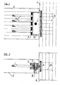
- FIGs 1 and 2 the connection of a glulam beam 3 to a glulam support 4 is shown in elevation and in plan.
- the farm part 2 sunk in the end grain is attached to the lower flange.
- the molded part can be completely embedded in the wooden cross-section.
- the threaded rods 1 are here arranged in a group one above the other.
- the molded part 5 is fastened to the support 4 in the present case with anchor nails 6. Instead of these nails 6, glued-in threaded rods 1 or screws can also be used.
- the two molded parts 2 and 5 are non-positively connected by a hinge pin 7.
- FIGS. 1 and 2 show a connection in which only glued-in threaded rods 1 are used to fasten the molded parts 2.5. Here, several groups of threaded rods 1 are arranged one above the other. A rigid connection is produced by two threaded pins 7 arranged outside the zero line. Otherwise the construction is carried out as in FIGS. 1 and 2,
Landscapes
- Engineering & Computer Science (AREA)
- Architecture (AREA)
- Physics & Mathematics (AREA)
- Electromagnetism (AREA)
- Civil Engineering (AREA)
- Structural Engineering (AREA)
- Joining Of Building Structures In Genera (AREA)
- Furniture Connections (AREA)
Applications Claiming Priority (2)
| Application Number | Priority Date | Filing Date | Title |
|---|---|---|---|
| DE19843401303 DE3401303C2 (de) | 1984-01-16 | 1984-01-16 | Verbindungsmittel für Holzbauteile |
| DE3401303 | 1984-01-16 |
Publications (2)
| Publication Number | Publication Date |
|---|---|
| EP0153566A2 true EP0153566A2 (fr) | 1985-09-04 |
| EP0153566A3 EP0153566A3 (fr) | 1986-04-30 |
Family
ID=6225075
Family Applications (1)
| Application Number | Title | Priority Date | Filing Date |
|---|---|---|---|
| EP85100346A Withdrawn EP0153566A3 (fr) | 1984-01-16 | 1985-01-15 | Moyen de liaison pour éléments de construction en bois |
Country Status (2)
| Country | Link |
|---|---|
| EP (1) | EP0153566A3 (fr) |
| DE (1) | DE3401303C2 (fr) |
Cited By (2)
| Publication number | Priority date | Publication date | Assignee | Title |
|---|---|---|---|---|
| ES2224819A1 (es) * | 2002-10-24 | 2005-03-01 | Universidad De Cordoba | Sistema de proteccion contra el fuego de uniones metalicas en estructuras de madera laminada encolada. |
| IT202300002172A1 (it) * | 2023-02-09 | 2024-08-09 | Rotho Blaas Srl Ovvero Rotho Blaas Gmbh | Sistema per il collegamento di almeno due elementi costruttivi di cui almeno un elemento costruttivo in legno e almeno un elemento costruttivo è una trave e un dispositivo per questo sistema |
Families Citing this family (7)
| Publication number | Priority date | Publication date | Assignee | Title |
|---|---|---|---|---|
| JPH0754405Y2 (ja) * | 1991-03-11 | 1995-12-18 | 清司 細川 | 木造建築材用締結金具と木造建築物の締結構造 |
| US5253945A (en) * | 1991-12-31 | 1993-10-19 | Kiyoshi Hosokawa | Metal connector for building and jointing structure of building using the same |
| DE29708115U1 (de) * | 1997-02-24 | 1997-07-10 | Schmid, Stefan, 86669 Königsmoos | Verbindungsbeschlag für zwei aneinanderstoßende Bauelemente, insbesondere im Holzbau |
| ATE239148T1 (de) | 1997-03-21 | 2003-05-15 | Bruno Alfons Furrer | Verbindungsvorrichtung und verwendung der verbindungsvorrichtung |
| DE20103856U1 (de) * | 2001-03-06 | 2001-06-21 | BMF Holzverbinder GmbH, 24939 Flensburg | Holzverbinder zum Verbinden zweier Bauteile, insbesondere von zwei Balken |
| DE10149537B4 (de) * | 2001-10-08 | 2005-09-22 | Heidemann Modular Space Systems Ltd. | Verbindungseinrichtung für eine Holz-Pfosten-Riegel-Verbindung |
| DE10153207B4 (de) * | 2001-10-27 | 2007-01-25 | Bohrenkämper, Gustav | Vorrichtung zum Verbinden zweier Holzbalken |
Family Cites Families (7)
| Publication number | Priority date | Publication date | Assignee | Title |
|---|---|---|---|---|
| GB191502257A (en) * | 1915-02-12 | 1916-02-17 | Samuel Ingham | Improvements in or relating to Military Huts, Bungalows, and other Buildings and Structures. |
| FR858534A (fr) * | 1939-07-31 | 1940-11-27 | Dispositif d'assemblage destiné à être utilisé principalement en ébénisterie | |
| US2280121A (en) * | 1941-05-26 | 1942-04-21 | Nathaniel P Green | Structural joint |
| DE819146C (de) * | 1948-10-02 | 1951-10-31 | Otto Pregitzer | Vorrichtung zum Verbinden von stumpf zusammenstossenden Moebel- bzw. Bauteilen |
| DE1811723U (de) * | 1958-07-08 | 1960-05-19 | Ernst Goehner A G | Fischbandbeschlag fuer fenster und tueren. |
| DE1875043U (de) * | 1963-04-13 | 1963-07-04 | Josef Frech | Scharnier fuer tueren und fenster. |
| GB1380353A (en) * | 1972-06-21 | 1975-01-15 | Birkeland O | Arrangements for readily assemblable furniture and like constructions |
-
1984
- 1984-01-16 DE DE19843401303 patent/DE3401303C2/de not_active Expired
-
1985
- 1985-01-15 EP EP85100346A patent/EP0153566A3/fr not_active Withdrawn
Cited By (3)
| Publication number | Priority date | Publication date | Assignee | Title |
|---|---|---|---|---|
| ES2224819A1 (es) * | 2002-10-24 | 2005-03-01 | Universidad De Cordoba | Sistema de proteccion contra el fuego de uniones metalicas en estructuras de madera laminada encolada. |
| IT202300002172A1 (it) * | 2023-02-09 | 2024-08-09 | Rotho Blaas Srl Ovvero Rotho Blaas Gmbh | Sistema per il collegamento di almeno due elementi costruttivi di cui almeno un elemento costruttivo in legno e almeno un elemento costruttivo è una trave e un dispositivo per questo sistema |
| WO2024165267A1 (fr) * | 2023-02-09 | 2024-08-15 | Rotho Blaas Gmbh/Srl | Système de raccordement d'au moins deux composants, dont au moins un composant est une poutre, et dispositif pour ce système |
Also Published As
| Publication number | Publication date |
|---|---|
| DE3401303C2 (de) | 1986-01-16 |
| DE3401303A1 (de) | 1985-07-25 |
| EP0153566A3 (fr) | 1986-04-30 |
Similar Documents
| Publication | Publication Date | Title |
|---|---|---|
| DE69224208T2 (de) | Verbindungselement für dachplatten | |
| DE3141807C1 (de) | Bauelement mit einer rechtwinkligen Platte,beispielsweise einem Paneel oder Schild | |
| DE2525791C3 (de) | Anordnung zum Verbinden zweier aufeinander stoßender platten- oder stangenförmiger Elemente | |
| DE2727286C2 (de) | Vorrichtung zum Verbinden einer mehrschichtigen Bauplatte mit einem zweiten Bauelemente | |
| EP0153566A2 (fr) | Moyen de liaison pour éléments de construction en bois | |
| DE2420688A1 (de) | Vorrichtung zum verbinden von rahmenelementen | |
| DE3879497T2 (de) | Metallstuetze. | |
| DE4305681C2 (de) | Befestigungsanordnung für ein Gestell eines Tasteninstruments | |
| DE10348264B3 (de) | Feststeller für eingenutete Rückwände an Kastenmöbeln | |
| EP1635075B1 (fr) | Dispositif de connection | |
| DE3909803C2 (de) | Industriefußboden aus Betonplatten | |
| DE3236169A1 (de) | Vorrichtung zum verbinden von rechtwinklig zueinander stehenden moebelplatten | |
| DE3628204C2 (fr) | ||
| DE8709769U1 (de) | Höhen- und breitenverstellbarer Pfostenanker | |
| EP0952267B1 (fr) | Elément pour la connection d'éléments plans de grilles de protection | |
| DE3416791A1 (de) | Koppelbares tafelelement | |
| DE102021102021A1 (de) | Montagevorrichtung zur Befestigung eines Objekts an einem zweischaligen Mauerwerk | |
| DE3016902C2 (de) | Polstercouch mit abklappbarer Seitenlehne | |
| DE3129918A1 (de) | Anordnung fuer die verbindung von saeulen architektonischer einheiten mit vorgegebenen abstaenden | |
| DE9407153U1 (de) | Handlauf aus Rundhölzern | |
| DE202024105710U1 (de) | Geländer, insbesondere Geländer aus Holz | |
| EP1430580A1 (fr) | Armoire electrique | |
| CH659681A5 (de) | Schiebetuere mit bodenfuehrung. | |
| DE9212445U1 (de) | Langgestrecktes Fassadenbauelement aus einem einteiligen, extrudierten Kunststoffprofil | |
| DE19912816A1 (de) | Geländerstütze für ein Baustellen-Schutzgeländer |
Legal Events
| Date | Code | Title | Description |
|---|---|---|---|
| PUAI | Public reference made under article 153(3) epc to a published international application that has entered the european phase |
Free format text: ORIGINAL CODE: 0009012 |
|
| AK | Designated contracting states |
Designated state(s): AT BE CH DE FR GB LI LU NL SE |
|
| PUAL | Search report despatched |
Free format text: ORIGINAL CODE: 0009013 |
|
| AK | Designated contracting states |
Kind code of ref document: A3 Designated state(s): AT BE CH DE FR GB LI LU NL SE |
|
| 17P | Request for examination filed |
Effective date: 19860520 |
|
| 17Q | First examination report despatched |
Effective date: 19870518 |
|
| RAP1 | Party data changed (applicant data changed or rights of an application transferred) |
Owner name: FORSTER, JAN |
|
| STAA | Information on the status of an ep patent application or granted ep patent |
Free format text: STATUS: THE APPLICATION IS DEEMED TO BE WITHDRAWN |
|
| 18D | Application deemed to be withdrawn |
Effective date: 19880129 |