EP0154257A2 - Dispositif pour fabriquer une feuille perforée en matière plastique - Google Patents
Dispositif pour fabriquer une feuille perforée en matière plastique Download PDFInfo
- Publication number
- EP0154257A2 EP0154257A2 EP85101860A EP85101860A EP0154257A2 EP 0154257 A2 EP0154257 A2 EP 0154257A2 EP 85101860 A EP85101860 A EP 85101860A EP 85101860 A EP85101860 A EP 85101860A EP 0154257 A2 EP0154257 A2 EP 0154257A2
- Authority
- EP
- European Patent Office
- Prior art keywords
- screen surface
- end rings
- cylindrical
- suction box
- plastic film
- Prior art date
- Legal status (The legal status is an assumption and is not a legal conclusion. Google has not performed a legal analysis and makes no representation as to the accuracy of the status listed.)
- Withdrawn
Links
Images
Classifications
-
- B—PERFORMING OPERATIONS; TRANSPORTING
- B26—HAND CUTTING TOOLS; CUTTING; SEVERING
- B26F—PERFORATING; PUNCHING; CUTTING-OUT; STAMPING-OUT; SEVERING BY MEANS OTHER THAN CUTTING
- B26F1/00—Perforating; Punching; Cutting-out; Stamping-out; Apparatus therefor
- B26F1/26—Perforating by non-mechanical means, e.g. by fluid jet
-
- B—PERFORMING OPERATIONS; TRANSPORTING
- B29—WORKING OF PLASTICS; WORKING OF SUBSTANCES IN A PLASTIC STATE IN GENERAL
- B29C—SHAPING OR JOINING OF PLASTICS; SHAPING OF MATERIAL IN A PLASTIC STATE, NOT OTHERWISE PROVIDED FOR; AFTER-TREATMENT OF THE SHAPED PRODUCTS, e.g. REPAIRING
- B29C59/00—Surface shaping of articles, e.g. embossing; Apparatus therefor
- B29C59/02—Surface shaping of articles, e.g. embossing; Apparatus therefor by mechanical means, e.g. pressing
- B29C59/06—Surface shaping of articles, e.g. embossing; Apparatus therefor by mechanical means, e.g. pressing using vacuum drums
Definitions
- the invention relates to a device for producing a perforated and possibly an embossed plastic film .. with a one-piece cylindrical screen surface on which the perforation and possibly the embossing of the film takes place, the plastic film directly on the screen surface or at least approximately in between Screen surface and a counter roll formed gap is extruded.
- the screen surface is arranged on a cylinder which consists of a support frame with axially extending strips on which the screen surface is supported. These strips are imaged on the plastic film when perforating under vacuum; which means that there is no perforation in the area of the strips.
- the object of the invention is to create a device with which a completely web-free perforation is possible.
- the cylindrical sieve surface is fixed in a rotationally fixed manner only with its two ends on disc-shaped end rings, that both end rings with drives are connected, which run synchronously to one another, and that a suction box extending at least approximately over the entire axial length of the screen surface is arranged within the cylindrical screen surface, on the two sealing strips facing the screen surface of which it can be supported, the suction box being fastened to two side frames, which carry the drive parts and the two disc-shaped end rings, which are pulled apart via spring elements which act on one of these end rings in such a way that an axial tensile stress is established in the screen surface.
- the film perforated in this way has an absolutely uniform perforation pattern.
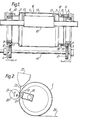
- the perforating device shown in Fig. 1 has an endless cylindrical screen surface 1, which is attached with its two end portions on disc-shaped end rings 2 and 3 rotatably. These two end rings are rotatably supported by ball bearings 4 and 5 on a side frame 6 and 7, respectively.
- the outer rings 8 and 9 of the two ball bearings 4 and 5 are equipped with teeth 10 and 11, in each of which a drive gear 12 or 13 engages. These two drive gears sit on a common drive shaft 14, which ensures that the two end rings 2 and 3 are driven synchronously with each other.
- a suction box 15 is arranged within the perforating device and is mounted on both side frames 6 and 7. On its side facing the sieve surface 1, the suction box is provided with a suction opening 16 which is formed by four sealing strips 17. The inside of the screen surface 1 is supported on these sealing strips 17.
- the end ring 3 is axially displaceably mounted on bolts 18 which are fastened to the outer ring 9 of the ball bearing 5. Between the heads of these bolts 18 and the end ring 3, compression springs 19 are clamped, which push the end ring 3 in the direction of the ball bearing 5 and thus away from the other end ring 2. This sets a tensile stress in the screen surface 1, which stiffens it.
- a counter roller 20 is arranged on the outside of the screen surface 1, opposite the sealing strips 17, the position of which can be changed along the arrow 21, as a result of which the free size of the suction opening 16 can be adjusted.
- An extruder nozzle 22 is arranged above the screen surface 1, from which a plastic film 23 is extruded into the gap formed between the screen surface 1 and the counter roller 20.
- the plastic film 23 can hit the screen surface or the counter roller slightly before the gap. Due to the suction effect, the plastic film 23 is perforated in the area of the suction opening and, depending on the design of the screen surface and possibly the counter roller, is additionally embossed. As a finished perforated and possibly embossed film, it is then removed from the screen surface.
Landscapes
- Engineering & Computer Science (AREA)
- Mechanical Engineering (AREA)
- Life Sciences & Earth Sciences (AREA)
- Forests & Forestry (AREA)
- Shaping Of Tube Ends By Bending Or Straightening (AREA)
- Moulds For Moulding Plastics Or The Like (AREA)
- Casting Or Compression Moulding Of Plastics Or The Like (AREA)
- Extrusion Moulding Of Plastics Or The Like (AREA)
- Processing And Handling Of Plastics And Other Materials For Molding In General (AREA)
- Combined Means For Separation Of Solids (AREA)
- Perforating, Stamping-Out Or Severing By Means Other Than Cutting (AREA)
Applications Claiming Priority (2)
| Application Number | Priority Date | Filing Date | Title |
|---|---|---|---|
| DE19843407318 DE3407318C1 (de) | 1984-02-29 | 1984-02-29 | Walze zum Herstellen einer perforierten und evtl. gepraegten Kunststoffolie |
| DE3407318 | 1984-02-29 |
Publications (2)
| Publication Number | Publication Date |
|---|---|
| EP0154257A2 true EP0154257A2 (fr) | 1985-09-11 |
| EP0154257A3 EP0154257A3 (fr) | 1985-11-06 |
Family
ID=6229126
Family Applications (1)
| Application Number | Title | Priority Date | Filing Date |
|---|---|---|---|
| EP85101860A Withdrawn EP0154257A3 (fr) | 1984-02-29 | 1985-02-21 | Dispositif pour fabriquer une feuille perforée en matière plastique |
Country Status (3)
| Country | Link |
|---|---|
| EP (1) | EP0154257A3 (fr) |
| JP (1) | JPS60204305A (fr) |
| DE (1) | DE3407318C1 (fr) |
Families Citing this family (2)
| Publication number | Priority date | Publication date | Assignee | Title |
|---|---|---|---|---|
| DE19524076C1 (de) * | 1995-07-01 | 1996-10-24 | Hcd Gmbh | Verfahren und Vorrichtung zur Herstellung eines oberflächenstrukturierten, folienartigen Halbzeugs aus einem Thermoplasten |
| BR112015013168A8 (pt) * | 2012-12-05 | 2023-02-14 | Tredegar Film Prod Corp | Método para proporcionar micro aberrações em um filme |
Family Cites Families (3)
| Publication number | Priority date | Publication date | Assignee | Title |
|---|---|---|---|---|
| US3709647A (en) * | 1970-10-21 | 1973-01-09 | Clear Pack Co | Apparatus for forming an embossed thermoplastic sheet |
| JPS5436617B2 (fr) * | 1973-02-07 | 1979-11-10 | ||
| US4157237A (en) * | 1978-07-10 | 1979-06-05 | Ethyl Corporation | Molding element for producing thermoplastic film |
-
1984
- 1984-02-29 DE DE19843407318 patent/DE3407318C1/de not_active Expired
-
1985
- 1985-02-21 EP EP85101860A patent/EP0154257A3/fr not_active Withdrawn
- 1985-02-27 JP JP3863185A patent/JPS60204305A/ja active Pending
Also Published As
| Publication number | Publication date |
|---|---|
| JPS60204305A (ja) | 1985-10-15 |
| DE3407318C1 (de) | 1985-11-07 |
| EP0154257A3 (fr) | 1985-11-06 |
Similar Documents
| Publication | Publication Date | Title |
|---|---|---|
| EP0037042B1 (fr) | Tambour pour le triage des semences et autres grains | |
| DE102008063786A1 (de) | Vorrichtung zum Vereinzeln von Teilen | |
| DE69201742T2 (de) | Modul für Druckperipherieschliessung. | |
| DE4314632C2 (de) | Fördereinrichtung für Gegenstände in Verpackungsmaschinen, insbesondere für Faltschachteln | |
| DE4344622A1 (de) | Räderfalzapparat für eine Rotationsdruckmaschine | |
| DE3346042C2 (fr) | ||
| DE3219556C2 (fr) | ||
| DE29713290U1 (de) | Rollenbandförderanlage | |
| DE3407318C1 (de) | Walze zum Herstellen einer perforierten und evtl. gepraegten Kunststoffolie | |
| DE2634108C3 (de) | Räderfalzapparat | |
| DE102021125587B3 (de) | Vorrichtung und Verfahren zum Ausrichten von Würsten | |
| DD248567A1 (de) | Vorrichtung zum fliessenden falzen von bogen- bzw. blattfoermigem material | |
| DE3121583A1 (de) | Abbeermaschine | |
| DE202012005944U1 (de) | Abzugsvorrichtung für stranggepresste Kunststoffprofile | |
| DE3318944C2 (de) | Faserbandablegeeinrichtung für eine Karde, Strecke o. dgl. | |
| DE2434357A1 (de) | Umlaufendes perforiergeraet | |
| DE2643152C3 (de) | Vorrichtung zum Anordnen eines oder zweier fortlaufender Fäden oder Streifen in einem Zick-zack-Muster auf einer drehbaren Trägerfläche | |
| DE2117311A1 (de) | Vorrichtung zur Entnahme von Papier | |
| EP0265543B1 (fr) | Dispositif pour séparer les pièces moulées par injection et les carottes, ou des éléments de formes et de dimensions différentes | |
| DE4215472C1 (en) | Welt filter for cleaning plastic melts - having sieve plate cut=out along the side which can hold filters in the form of ring members | |
| DE3613117C2 (de) | Faltvorrichtung | |
| EP0714770A1 (fr) | Dispositif pour transporter du papier | |
| DE2007368A1 (de) | Vorrichtung zum ziehharmonikaartigen Falten von Bögen | |
| EP0095515B1 (fr) | Dispositif de dosage pour des flocs | |
| DE2241910B2 (de) | Selbsttätiger Bogenanleger für Druckmaschinen |
Legal Events
| Date | Code | Title | Description |
|---|---|---|---|
| PUAI | Public reference made under article 153(3) epc to a published international application that has entered the european phase |
Free format text: ORIGINAL CODE: 0009012 |
|
| PUAL | Search report despatched |
Free format text: ORIGINAL CODE: 0009013 |
|
| AK | Designated contracting states |
Designated state(s): AT BE CH DE FR GB IT LI NL SE |
|
| AK | Designated contracting states |
Designated state(s): AT BE CH DE FR GB IT LI NL SE |
|
| STAA | Information on the status of an ep patent application or granted ep patent |
Free format text: STATUS: THE APPLICATION IS DEEMED TO BE WITHDRAWN |
|
| 18D | Application deemed to be withdrawn |
Effective date: 19860707 |
|
| RIN1 | Information on inventor provided before grant (corrected) |
Inventor name: MERZ, WINFRIED, DR. Inventor name: SCHMIDT, THEO Inventor name: REINKE, DIETMAR, DR. Inventor name: SICKERT, PETER |