EP0154543A2 - Moteur submersible - Google Patents
Moteur submersible Download PDFInfo
- Publication number
- EP0154543A2 EP0154543A2 EP85301475A EP85301475A EP0154543A2 EP 0154543 A2 EP0154543 A2 EP 0154543A2 EP 85301475 A EP85301475 A EP 85301475A EP 85301475 A EP85301475 A EP 85301475A EP 0154543 A2 EP0154543 A2 EP 0154543A2
- Authority
- EP
- European Patent Office
- Prior art keywords
- thrust
- motor
- bearing
- shaft
- radial
- Prior art date
- Legal status (The legal status is an assumption and is not a legal conclusion. Google has not performed a legal analysis and makes no representation as to the accuracy of the status listed.)
- Granted
Links
Images

Classifications
-
- H—ELECTRICITY
- H02—GENERATION; CONVERSION OR DISTRIBUTION OF ELECTRIC POWER
- H02K—DYNAMO-ELECTRIC MACHINES
- H02K5/00—Casings; Enclosures; Supports
- H02K5/04—Casings or enclosures characterised by the shape, form or construction thereof
- H02K5/16—Means for supporting bearings, e.g. insulating supports or means for fitting bearings in the bearing-shields
- H02K5/167—Means for supporting bearings, e.g. insulating supports or means for fitting bearings in the bearing-shields using sliding-contact or spherical cap bearings
- H02K5/1672—Means for supporting bearings, e.g. insulating supports or means for fitting bearings in the bearing-shields using sliding-contact or spherical cap bearings radially supporting the rotary shaft at both ends of the rotor
-
- H—ELECTRICITY
- H02—GENERATION; CONVERSION OR DISTRIBUTION OF ELECTRIC POWER
- H02K—DYNAMO-ELECTRIC MACHINES
- H02K5/00—Casings; Enclosures; Supports
- H02K5/04—Casings or enclosures characterised by the shape, form or construction thereof
- H02K5/12—Casings or enclosures characterised by the shape, form or construction thereof specially adapted for operating in liquid or gas
- H02K5/128—Casings or enclosures characterised by the shape, form or construction thereof specially adapted for operating in liquid or gas using air-gap sleeves or air-gap discs
- H02K5/1285—Casings or enclosures characterised by the shape, form or construction thereof specially adapted for operating in liquid or gas using air-gap sleeves or air-gap discs of the submersible type
Definitions
- the present invention relates to a submersible motor and, more particularly, to a submersible motor adapted for use with a submersible pump.
- a submersible motor used in conjunction with a submersible pump used as a deep well pump is generally limited in size, particularly with respect to its horizontal sectional area, due to the limited diametral dimension of such deep well.
- the axial length of the whole submersible- motor deep well pump is made relatively long to provide the required capacity.
- the motor is generally disposed in the lowermost position and a pump is attached above the motor through a motor shaft extending upwardly from the motor.
- the lowermost portion of the motor shaft is required to be rotatably supported by bearing means with respect to the radial load as well as the thrust load. Therefore, it has been necessary to employ a radial bearing and a thrust bearing independently.
- the axial length of the lower bearing portion is also made relatively long because of the dimensional limitation with regard to the diameter of the motor.
- the axial length of a lower radial bearing means is devised to be within the axial length of the thrust bearing means. More particularly, a thrust disk secured to the motor shaft at the lower portion thereof is utilized as a jornal portion of the motor shaft which bears against the bearing surface of the metal bearing serving as a radial bearing which'may be made with a relatively large diameter having a relatively short axial length.
- Fig. 1 a cross sectional view of the coventional prior art submersible motor is shown wherein a longitudinal axis thereof, which is usually vertical in use, is shown in a horizontal direction for the purpose of illustration and its upper side is seen on the right hand side in Fig. 1.
- the submersible motor illustrated is of a canned type and comprises a cylindrical frame 1 within which a stator 2 is housed and sealed within a stator can 3 made of sheet metal.
- a stator 2 is housed and sealed within a stator can 3 made of sheet metal.
- an upper side plate 4 and a lower side plate 5 are press fitted into the frame, respectively.
- the upper and lower ends of the can 3 are sealed to the upper side plate 4 and the lower side plate 5, respectively by such means as welding.
- a rotor 6 is disposed in opposing relation to the stator 2 with being mounted on a motor shaft 7 and the outer cylindrical surface of the rotor and the inner cylindrical surface are arranged to have a small gap therebetween.
- the motor shaft 7 is rotatably supported by an upper radial metal bearing 8 and a lower radial-metal bearing 9 which are stationarily installed in an upper bracket 10 and a lower bracket 11, resepctively.
- the upper and lower brackets 10 and 11 are sealingly secured by fastening means such as bolts to the upper side plate 4, and the lower side plate 5, respectively with sealing means therebetween.
- the upper portion of the motor shaft 7 is sealed by a mechanical seal 12 above which further protecting means such as sand-slingers, etc., are provided.
- the lower side of the motor is also sealed as will be expalined later. Inside of the frame, liquid is filled through a port 13, this liquid serving to lubricate the bearings.
- a thrust disk 14 is attached to the shaft through a key 15 and is adapted to abut against a step portion 7a of the motor shaft 7 so that the thrust is transmitted to the disk 14.
- the thrust disk 14 is provided with a center portion 14a circularly raised in the lower direction and an annular flat disk 16 is disposed around the center portion 14a.
- a pin 17 is press fitted into the thrust disk 14 and the opposite end of the pin 17 is loosely received in a hole provided on the annular disk 16.
- a thrust housing 18 is also secured to the lower bracket 11 by fastening means such as bolts with sealing means therebetween.
- a thrust pad 19 is concentrically disposed relative to the annular disk 16 in abutting relation to the disk 16.
- the thrust disk 14, annular disk 16 and thrust pad 19 are suspended in the thrust housing 18 by a first self-aligning annular collar 20 and a secozrd self-aligning annular collar 21 with interposing diametrally arranged balls 22 between the thrust pad 19 and the first annular collar 20, another group of diametrally arranged balls 23 interposed between the first and second self-aligning annular collars 20 and 21 and diametrally arranged studs 24 mounted on the second annular collar 21 and having spherical heads between the second annular collar 21 and the inner bottom of the thrust housing 18, the diametral arrangements of balls 22.
- a diaphragm chamber including a diaphragm 25 is provided so as to accommodate variation in the volume of liquid contained within the motor casing 1.
- the submersible motor is adapted to couple a submersible pump (as schematically shown by dotted lines on the right hand side of Fig. 1) at the upper end of the motor shaft 7 and electric power is supplied to the stator 2 through a cable 26 connected to the motor at the upper bracket 10 through a liquid-proof connector.
- a submersible pump as schematically shown by dotted lines on the right hand side of Fig. 1
- bearing means for supporting the motor shaft generally comprises a thrust bearing means in addition to a radial bearing means and these two bearing means are arranged in adjacent relation along the axial direction of the shaft. Therefore, the required axial length for accommodating such bearing means is increased, whereby the overall length of the motor becomes lengthy and the weight thereof is also increased.
- bearing means be installed in the space within the stator can; however such an attempt was revealed as unsatisfactory because of the presence of magnetic field which causes abraded particles to be attracted to the bearing means.
- bearing means and the coil of the stator become sources for generating heat during the operation and it is not desirable to have such heat sources occurring at almost the same portion. Accordingly, it has been desired to have a submersible pump directed to the objects expalined hereinbefore which is free from the drawbacks discussed above.
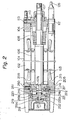
- Fig. 2 wherein an embodiment according to the present invention is illustrated.
- those portions which are similar to those in Fig. 1 are given the same reference numerals with the addition of "100" thereto, in each case.
- Those portions not specifically explained hereinafter with reference to such reference numerals are. to be understood by referring to those explained in connection with Fig. 1.
- a radial metal bearing 209 having an inner diameter almost equivalent to the inner diameter of the stator can 103 is fitted thereinto and stationarily held in place by means of a set screw 250.
- the lower side of the radial metal bearing 209 projects slightly in the downward direction and is received into a thrust housing 218 with a seal 251 disposed at the juncture of the housing 218, lower side plate 204 and the metal bearing 209.
- the housing 218 is also fastened to the cylindrical frame 101 and the lower side plate 205 by a suitable fastening means.
- a thrust disk 214 is installed with a key 215 disposed therebetween so as to rotate with the shaft 107 and it receives the thrust via a shoulder portion 107a of the shaft.
- the radially outer peripheral portion of the thrust disk 214 is made as a cylindrical surface adapted to transmit the radial load of the shaft to the metal bearing 209. Since the inner diameter of the metal bearing 209 is made relatively large, enough bearing surface area is provided for the radial load even though the axial length of the metal bearing 209 is made shorter.
- the under side of the metal bearing 209 is concentrically bored to provide a recessed seat 214a designed to receive an annular thrust carbon plate 216 therein.
- a pin 217 is mounted at one end thereof on the thrust disk 214 and the opposite end is received in a blind hole on the carbon plate 216 such as to rotate the plate 21 with the thrust disk 214.
- a spherical projection end 219a of a leveling disk 219 is received and, within an annular groove 219b provided on the upper surface of the leveling disk 21, several tilting pads 220 (for example, three to six in number) are disposed so that the respective upper surfaces of the tilting pads 220 makes sliding contact with the lower surface of the thrust carbon plate 216.
- Each of the tilting pads 220 is respectively provided with a downwardly directed projection 220a, so that the tilting pads 220 may be tiltable so as to provide proper sliding contact relative to the carbon plate 216.
- An "0" ring 221 installed between the leveling disk 219 and the tilting pads 220 serves to maintain the tilting pads 220 in place by engaging the grooves in both the leveling disk 219 and tilting pads 220 irrespective of the posture of the leveling disk 219.
- the motor shaft 107 Upon energization of the stator through a cable 126, the motor shaft 107 rotates and thus the thrust disk 214 is rotated together with the thrust carbon plate 216 so that the radial load is borne by means of the radial metal bearings 108 and 209 and the thrust load is borne by the carbon plate 216 and tilting pads 220.
- grooves 222 are axially provided on the inner surface of the metal bearing 209, one of which is shown in Fig. 2.
- the thrust carbon plate 216 extends outside from the recessed seat 214a; however, the depth of the recessed seat 214a may be bored deeper so that the thrust carbon plate 216 may be received completely within the recessed depth of the seat 214a. Further, the depth of the seat may be made even deeper to receive the tilting pads 220 therein.
- one of the radial bearings supporting the shaft especially the lower side radial bearing, is able to be disposed within the axial length "L" of the thrust bearing means by reason of the provision of the-.recessed seat 214a into which at least some components of the thrust bearing means are received. Accordingly, the total length of the submersible motor is made shorter by the axial dimension of the radial bearings heretofore required. Further advantages according to the present invention are seen in the following points.
- a lower bracket such as the bracket 11 for supporting the radial bearing 9 (Fig. 1) is made unnecessary whereby the number of components is reduced and preferred separation of bearing means from the stator coil is easily achieved because of the fact that provision of a space in the axial direction for the radial bearings is made unnecessary.
Landscapes
- Engineering & Computer Science (AREA)
- Power Engineering (AREA)
- Motor Or Generator Frames (AREA)
- Structures Of Non-Positive Displacement Pumps (AREA)
- Permanent Magnet Type Synchronous Machine (AREA)
- Sliding-Contact Bearings (AREA)
- Control Of Throttle Valves Provided In The Intake System Or In The Exhaust System (AREA)
- Compressor (AREA)
- Lubrication Of Internal Combustion Engines (AREA)
- Catching Or Destruction (AREA)
Priority Applications (1)
| Application Number | Priority Date | Filing Date | Title |
|---|---|---|---|
| AT85301475T ATE52394T1 (de) | 1984-03-05 | 1985-03-04 | Tauchbarer motor. |
Applications Claiming Priority (2)
| Application Number | Priority Date | Filing Date | Title |
|---|---|---|---|
| JP31543/84U | 1984-03-05 | ||
| JP1984031543U JPS60144749U (ja) | 1984-03-05 | 1984-03-05 | 水中モ−タ |
Publications (3)
| Publication Number | Publication Date |
|---|---|
| EP0154543A2 true EP0154543A2 (fr) | 1985-09-11 |
| EP0154543A3 EP0154543A3 (en) | 1986-07-30 |
| EP0154543B1 EP0154543B1 (fr) | 1990-05-02 |
Family
ID=12334101
Family Applications (1)
| Application Number | Title | Priority Date | Filing Date |
|---|---|---|---|
| EP85301475A Expired - Lifetime EP0154543B1 (fr) | 1984-03-05 | 1985-03-04 | Moteur submersible |
Country Status (6)
| Country | Link |
|---|---|
| US (1) | US4636672A (fr) |
| EP (1) | EP0154543B1 (fr) |
| JP (1) | JPS60144749U (fr) |
| AT (1) | ATE52394T1 (fr) |
| DE (1) | DE3577500D1 (fr) |
| DK (1) | DK163085C (fr) |
Cited By (4)
| Publication number | Priority date | Publication date | Assignee | Title |
|---|---|---|---|---|
| US4985637A (en) * | 1988-06-08 | 1991-01-15 | Mitsubishi Denki Kabushiki Kaisha | Support bearing for coaxial starter |
| EP0471974A3 (en) * | 1990-07-13 | 1993-05-12 | Ebara Corporation | Canned motor |
| WO1994004827A1 (fr) * | 1992-08-19 | 1994-03-03 | Bw/Ip International, Inc. | Pompe centrifuge multi-etagee comprenant un palier de poussee etanche |
| CN101153628B (zh) * | 2006-12-15 | 2010-09-22 | 江门市瑞荣泵业有限公司 | 止推轴承 |
Families Citing this family (9)
| Publication number | Priority date | Publication date | Assignee | Title |
|---|---|---|---|---|
| US5321328A (en) * | 1992-12-16 | 1994-06-14 | Ide Russell D | Motor bearing with rotatable guide |
| RU2141157C1 (ru) * | 1997-05-13 | 1999-11-10 | Семенов Олег Степанович | Электрическая машина |
| US20030218400A1 (en) * | 2002-05-24 | 2003-11-27 | Rimmel Dennis L. | Induction motor and method of providing axial flow in a submerged induction motor |
| EP2096737B1 (fr) * | 2008-02-29 | 2013-09-11 | Grundfos Management A/S | Moteur submersible |
| US20100164303A1 (en) * | 2008-12-31 | 2010-07-01 | Schlumberger Technology Corporation | Submersible motor with ferrofluid gap |
| FR3009586B1 (fr) * | 2013-08-06 | 2015-08-28 | Snecma | Dispositif d'alimentation en ergol de moteur-fusee |
| JP6513990B2 (ja) * | 2015-03-23 | 2019-05-15 | 株式会社荏原製作所 | モータ |
| CN204794403U (zh) * | 2015-06-05 | 2015-11-18 | 厦门建霖工业有限公司 | 一种水力发电机二次包胶防水结构 |
| JP2024152137A (ja) * | 2023-04-14 | 2024-10-25 | 株式会社荏原製作所 | 水中電動機 |
Family Cites Families (8)
| Publication number | Priority date | Publication date | Assignee | Title |
|---|---|---|---|---|
| US2325404A (en) * | 1941-12-18 | 1943-07-27 | Gen Electric | Thrust bearing arrangement |
| US3195466A (en) * | 1959-05-25 | 1965-07-20 | Porter Co Inc H K | Electric motor construction |
| US4042847A (en) * | 1974-07-10 | 1977-08-16 | Grundfos A/S | Liquid-filled submersible electromotor |
| JPS5840895B2 (ja) * | 1978-05-08 | 1983-09-08 | 株式会社日立製作所 | 水中モ−タ |
| US4496866A (en) * | 1981-01-17 | 1985-01-29 | Mitsubishi Denki Kabushiki Kaisha | Submersible electric motor and method of manufacturing the same |
| US4421999A (en) * | 1981-03-02 | 1983-12-20 | Hughes Tool Company | Submersible pump seal section with multiple bellows |
| AU8314182A (en) * | 1981-11-25 | 1983-06-02 | Marley-Wylain Co., The | Submersible motor |
| US4435661A (en) * | 1982-05-10 | 1984-03-06 | Hughes Tool Company | Submersible pump motor flexible bearing |
-
1984
- 1984-03-05 JP JP1984031543U patent/JPS60144749U/ja active Granted
-
1985
- 1985-02-27 US US06/706,300 patent/US4636672A/en not_active Expired - Lifetime
- 1985-03-04 AT AT85301475T patent/ATE52394T1/de not_active IP Right Cessation
- 1985-03-04 DK DK099385A patent/DK163085C/da active
- 1985-03-04 DE DE8585301475T patent/DE3577500D1/de not_active Expired - Lifetime
- 1985-03-04 EP EP85301475A patent/EP0154543B1/fr not_active Expired - Lifetime
Cited By (5)
| Publication number | Priority date | Publication date | Assignee | Title |
|---|---|---|---|---|
| US4985637A (en) * | 1988-06-08 | 1991-01-15 | Mitsubishi Denki Kabushiki Kaisha | Support bearing for coaxial starter |
| EP0471974A3 (en) * | 1990-07-13 | 1993-05-12 | Ebara Corporation | Canned motor |
| WO1994004827A1 (fr) * | 1992-08-19 | 1994-03-03 | Bw/Ip International, Inc. | Pompe centrifuge multi-etagee comprenant un palier de poussee etanche |
| US5340272A (en) * | 1992-08-19 | 1994-08-23 | Bw/Ip International, Inc. | Multi-stage centrifugal pump incorporating a sealed thrust bearing |
| CN101153628B (zh) * | 2006-12-15 | 2010-09-22 | 江门市瑞荣泵业有限公司 | 止推轴承 |
Also Published As
| Publication number | Publication date |
|---|---|
| DK163085C (da) | 1992-06-09 |
| DK163085B (da) | 1992-01-13 |
| DK99385A (da) | 1985-09-06 |
| EP0154543B1 (fr) | 1990-05-02 |
| DK99385D0 (da) | 1985-03-04 |
| ATE52394T1 (de) | 1990-05-15 |
| US4636672A (en) | 1987-01-13 |
| EP0154543A3 (en) | 1986-07-30 |
| JPH0139089Y2 (fr) | 1989-11-22 |
| DE3577500D1 (de) | 1990-06-07 |
| JPS60144749U (ja) | 1985-09-26 |
Similar Documents
| Publication | Publication Date | Title |
|---|---|---|
| EP0154543B1 (fr) | Moteur submersible | |
| US5503520A (en) | Pump for filtration systems | |
| KR101874070B1 (ko) | 전기기기, 특히 펌프장치의 전기기기 | |
| US4391547A (en) | Quick release downhole motor coupling | |
| US4032203A (en) | Bearing arrangement for the armature shaft of an electric motor | |
| US2240569A (en) | Multiple section motor | |
| US4841183A (en) | Dynamoelectric machine construction and method | |
| US4862026A (en) | Motor unit bearing | |
| US5237228A (en) | Submersible machine | |
| JPH0637890B2 (ja) | 発電電気機械の軸受装置 | |
| EP1014538A2 (fr) | Anneau de serrage élastique | |
| JPH0381584A (ja) | 弾性内部取付装置を備えた気密コンプレッサー | |
| US4638198A (en) | Electric submergible motor with bearing assembly isolated from axial loads | |
| US5977673A (en) | Armature shaft support structure for use in an electric motor | |
| US6715913B2 (en) | Shaft bearing support method and apparatus | |
| JPH0670361B2 (ja) | スクロ−ル形流体機械 | |
| JPH086820B2 (ja) | シール装置 | |
| EP4068587B1 (fr) | Machine électrique rotative | |
| JPH05263824A (ja) | 電動機の軸受装置 | |
| CN223829144U (zh) | 电机及料理机 | |
| JP7715886B2 (ja) | 建設機械 | |
| CN216851621U (zh) | 马达组件 | |
| CN216464412U (zh) | 一种电动工具头壳总成结构 | |
| KR102938742B1 (ko) | 모터 | |
| JPH04272557A (ja) | 2軸独立駆動装置 |
Legal Events
| Date | Code | Title | Description |
|---|---|---|---|
| PUAI | Public reference made under article 153(3) epc to a published international application that has entered the european phase |
Free format text: ORIGINAL CODE: 0009012 |
|
| AK | Designated contracting states |
Designated state(s): AT DE FR GB IT NL SE |
|
| PUAL | Search report despatched |
Free format text: ORIGINAL CODE: 0009013 |
|
| AK | Designated contracting states |
Kind code of ref document: A3 Designated state(s): AT DE FR GB IT NL SE |
|
| 17P | Request for examination filed |
Effective date: 19870107 |
|
| 17Q | First examination report despatched |
Effective date: 19880822 |
|
| ITF | It: translation for a ep patent filed | ||
| GRAA | (expected) grant |
Free format text: ORIGINAL CODE: 0009210 |
|
| AK | Designated contracting states |
Kind code of ref document: B1 Designated state(s): AT DE FR GB IT NL SE |
|
| PG25 | Lapsed in a contracting state [announced via postgrant information from national office to epo] |
Ref country code: SE Effective date: 19900502 Ref country code: NL Effective date: 19900502 Ref country code: FR Effective date: 19900502 Ref country code: AT Effective date: 19900502 |
|
| REF | Corresponds to: |
Ref document number: 52394 Country of ref document: AT Date of ref document: 19900515 Kind code of ref document: T |
|
| REF | Corresponds to: |
Ref document number: 3577500 Country of ref document: DE Date of ref document: 19900607 |
|
| EN | Fr: translation not filed | ||
| NLV1 | Nl: lapsed or annulled due to failure to fulfill the requirements of art. 29p and 29m of the patents act | ||
| PLBE | No opposition filed within time limit |
Free format text: ORIGINAL CODE: 0009261 |
|
| STAA | Information on the status of an ep patent application or granted ep patent |
Free format text: STATUS: NO OPPOSITION FILED WITHIN TIME LIMIT |
|
| 26N | No opposition filed | ||
| ITTA | It: last paid annual fee | ||
| PGFP | Annual fee paid to national office [announced via postgrant information from national office to epo] |
Ref country code: DE Payment date: 20000328 Year of fee payment: 16 |
|
| PGFP | Annual fee paid to national office [announced via postgrant information from national office to epo] |
Ref country code: GB Payment date: 20010220 Year of fee payment: 17 |
|
| PG25 | Lapsed in a contracting state [announced via postgrant information from national office to epo] |
Ref country code: DE Free format text: LAPSE BECAUSE OF NON-PAYMENT OF DUE FEES Effective date: 20020101 |
|
| REG | Reference to a national code |
Ref country code: GB Ref legal event code: IF02 |
|
| PG25 | Lapsed in a contracting state [announced via postgrant information from national office to epo] |
Ref country code: GB Free format text: LAPSE BECAUSE OF NON-PAYMENT OF DUE FEES Effective date: 20020304 |
|
| GBPC | Gb: european patent ceased through non-payment of renewal fee |
Effective date: 20020304 |