EP0155460A2 - Folienschneidemaschine - Google Patents
Folienschneidemaschine Download PDFInfo
- Publication number
- EP0155460A2 EP0155460A2 EP85100668A EP85100668A EP0155460A2 EP 0155460 A2 EP0155460 A2 EP 0155460A2 EP 85100668 A EP85100668 A EP 85100668A EP 85100668 A EP85100668 A EP 85100668A EP 0155460 A2 EP0155460 A2 EP 0155460A2
- Authority
- EP
- European Patent Office
- Prior art keywords
- recoiler
- sections
- mandrel
- shaft
- drum
- Prior art date
- Legal status (The legal status is an assumption and is not a legal conclusion. Google has not performed a legal analysis and makes no representation as to the accuracy of the status listed.)
- Granted
Links
Images
Classifications
-
- B—PERFORMING OPERATIONS; TRANSPORTING
- B65—CONVEYING; PACKING; STORING; HANDLING THIN OR FILAMENTARY MATERIAL
- B65H—HANDLING THIN OR FILAMENTARY MATERIAL, e.g. SHEETS, WEBS, CABLES
- B65H18/00—Winding webs
- B65H18/08—Web-winding mechanisms
- B65H18/10—Mechanisms in which power is applied to web-roll spindle
- B65H18/106—Mechanisms in which power is applied to web-roll spindle for several juxtaposed strips
-
- B—PERFORMING OPERATIONS; TRANSPORTING
- B65—CONVEYING; PACKING; STORING; HANDLING THIN OR FILAMENTARY MATERIAL
- B65H—HANDLING THIN OR FILAMENTARY MATERIAL, e.g. SHEETS, WEBS, CABLES
- B65H18/00—Winding webs
- B65H18/08—Web-winding mechanisms
- B65H18/10—Mechanisms in which power is applied to web-roll spindle
- B65H18/103—Reel-to-reel type web winding and unwinding mechanisms
-
- B—PERFORMING OPERATIONS; TRANSPORTING
- B65—CONVEYING; PACKING; STORING; HANDLING THIN OR FILAMENTARY MATERIAL
- B65H—HANDLING THIN OR FILAMENTARY MATERIAL, e.g. SHEETS, WEBS, CABLES
- B65H35/00—Delivering articles from cutting or line-perforating machines; Article or web delivery apparatus incorporating cutting or line-perforating devices, e.g. adhesive tape dispensers
- B65H35/02—Delivering articles from cutting or line-perforating machines; Article or web delivery apparatus incorporating cutting or line-perforating devices, e.g. adhesive tape dispensers from or with longitudinal slitters or perforators
-
- B—PERFORMING OPERATIONS; TRANSPORTING
- B65—CONVEYING; PACKING; STORING; HANDLING THIN OR FILAMENTARY MATERIAL
- B65H—HANDLING THIN OR FILAMENTARY MATERIAL, e.g. SHEETS, WEBS, CABLES
- B65H2301/00—Handling processes for sheets or webs
- B65H2301/40—Type of handling process
- B65H2301/41—Winding, unwinding
- B65H2301/414—Winding
- B65H2301/4148—Winding slitting
-
- B—PERFORMING OPERATIONS; TRANSPORTING
- B65—CONVEYING; PACKING; STORING; HANDLING THIN OR FILAMENTARY MATERIAL
- B65H—HANDLING THIN OR FILAMENTARY MATERIAL, e.g. SHEETS, WEBS, CABLES
- B65H2301/00—Handling processes for sheets or webs
- B65H2301/40—Type of handling process
- B65H2301/41—Winding, unwinding
- B65H2301/414—Winding
- B65H2301/4148—Winding slitting
- B65H2301/41486—Winding slitting winding on two or more winding shafts simultaneously
-
- B—PERFORMING OPERATIONS; TRANSPORTING
- B65—CONVEYING; PACKING; STORING; HANDLING THIN OR FILAMENTARY MATERIAL
- B65H—HANDLING THIN OR FILAMENTARY MATERIAL, e.g. SHEETS, WEBS, CABLES
- B65H2405/00—Parts for holding the handled material
- B65H2405/40—Holders, supports for rolls
- B65H2405/45—Shafts for winding/unwinding
Definitions
- This invention relates to a method of an apparatus for recoiling the metal strips which are produced when a coil of sheet metal is slit parallel to its longitudinal axis.
- a method of an apparatus for recoiling the metal strips which are produced when a coil of sheet metal is slit parallel to its longitudinal axis Particularly when slitting thin sheet in large coils, uneven thickness over the width of the sheet will often result in the slit strips differing in length. It is usual when rolling metal sheet and metal foil, that the thickness of the product varies across its width, and the result of this is that the metal strips which are cut along the length of the sheet are longer where the sheet is thin than where it is thicker. As a result, when several strips are recoiled onto a common mandrel with the same rotational speed along its entire length, the coils containing the longest strips will be loosely wound.
- German provisional patent attempts to solve this problem by dividing the recoiler mandrel up into sections, so that it consists of a number of cylinders, or drums, suspended on a common shaft, friction blocks being placed inside the sections, so arranged that the friction can be varied by varying pneumatic or hydraulic pressure, enabling the sections, to a certain extent, to rotate at different speeds.
- This system requires a very exact control of the pressure as the coils of strip build up. To avoid uneven strip tension, the operator must ensure that the friction surfaces for all the sections are continuously sliding against one another. This is difficult to achieve, and can result in surface scratches and uneven coiling.
- a corresponding solution to the problem is that the friction elements consist of friction discs placed between the sections, the friction force being varied by pressing the sections together by axial hydraulic or pneumatic pressure. Also this solution gives, in principle, different coiling tensions, and has the same disadvantages.
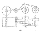
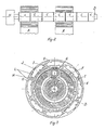
- the solution consists in having a number of mandrel sections (C, fig. 2) rotatably suspended on a common shaft (D, fig. 3), and mounted on this common shaft there is a hydraulic rotating unit (E, fig. 3) for each mandrel section, with gear transmission between unit and section. Hydraulically, the pressure sides and section sides respectively of all the hydraulic rotating units are interconnected, and in this way a differential effect is achieved.
- the hydraulic unit When a rotational force is applied to one of the mandrel sections, the hydraulic unit (the motor) will be driven as a pump, and the oil pressure will drive the other units as motors in the opposite direction of rotation until all the sections are loaded with the same rotational force. The sum of the rotational speeds of the motors will be equal to that of the pump.
- the hydraulic units (E) function as both motors and pumps, the pressure and suction sides respectively being interconnected, so that when a rotational force in a given direction is applied to one or more sections, the remaining sections will be driven in the opposite direction in such a manner that the sum of the mandrel sections' relative rotations with respect to the recoiler shaft is zero, and the rotational force applied to each section is approximately equal when we disregard transmission losses; and the system operates thus as a multiple differential mandrel.
- an apparatus has thus been designed for producing evenly and tightly wound coils of strip made from an initial coil of sheet, slit parallel to its longitudinal axis, to make two or more strips (A, fig. 1) in a conventional slitting machine (fig. 1), in which any differences in the length of the strips, arising from the slitting process, are accomodated, and in which the strip tension is maintained approx. constant during recoiling, the recoiling mandrel(s) of the slitting machine being divided into mandrel sections (C, fig.
- the system will adjust itself to a state in which the sum of the relative rotational speeds of the mandrel sections with respect to the shaft is zero, and the rotational forces for all of the sections are the same.
- the one or more recoiler mandrel (s) is (are) divided into mandrel sections (see fig. 2) suspended on the recoiler shaft, each section receiving its rotational force from a drive (K) via the recoiler shaft (D) with power supplied via a hydraulic unit fixed on the shaft and hydraulically interlinked with corresponding units for the remaining mandrel sections in a closed hydraulic system.
- FIG. 3 sketches, in principle, the construction of each recoiler mandrel section.
- a split outer expansion drum (H) and an inner drum (F) have respectively inner and outer corresponding inclined surfaces, so shaped that the outer drum will expand to a given diameter when it is rotated through a given angle in the direction opposite to that of the recoiling rotation, and the inclined surfaces are displaced in relationship to on another in that they roll on rollers (I). If the expansion drum is rotated in the opposite direction, it will collapse radially with the help of springs (J).
- the recoiler mandrels are built with the appropriate number of sections determined by the narrowest strip which is to be coiled. Unused sections in this recoiling unit can be made inoperative by operating a hydraulic valve.
Landscapes
- Winding Of Webs (AREA)
- Winding, Rewinding, Material Storage Devices (AREA)
- Control And Other Processes For Unpacking Of Materials (AREA)
- Basic Packing Technique (AREA)
Applications Claiming Priority (2)
| Application Number | Priority Date | Filing Date | Title |
|---|---|---|---|
| NO840274A NO153686C (no) | 1984-01-25 | 1984-01-25 | Differensialspole for baandskjaeremaskinhaspel. |
| NO840274 | 1984-01-25 |
Publications (3)
| Publication Number | Publication Date |
|---|---|
| EP0155460A2 true EP0155460A2 (de) | 1985-09-25 |
| EP0155460A3 EP0155460A3 (en) | 1987-02-04 |
| EP0155460B1 EP0155460B1 (de) | 1990-01-03 |
Family
ID=19887459
Family Applications (1)
| Application Number | Title | Priority Date | Filing Date |
|---|---|---|---|
| EP85100668A Expired EP0155460B1 (de) | 1984-01-25 | 1985-01-23 | Folienschneidemaschine |
Country Status (6)
| Country | Link |
|---|---|
| US (1) | US4593864A (de) |
| EP (1) | EP0155460B1 (de) |
| JP (1) | JPS60216920A (de) |
| DD (1) | DD228233A5 (de) |
| DE (1) | DE3575117D1 (de) |
| NO (1) | NO153686C (de) |
Cited By (3)
| Publication number | Priority date | Publication date | Assignee | Title |
|---|---|---|---|---|
| DE3900960A1 (de) * | 1989-01-14 | 1990-08-02 | Sundwiger Eisen Maschinen | Vorrichtung zum laengsteilen eines bandes und aufwickeln der streifen des geteilten bandes |
| EP0409311A1 (de) * | 1989-07-17 | 1991-01-23 | SOLVAY (Société Anonyme) | Mehrbreiten Wickelmaschine |
| WO2002068304A1 (de) * | 2001-02-24 | 2002-09-06 | Wt Wickeltechnik Gmbh | Wickelwelle zum aufwickeln bandförmiger materialien |
Families Citing this family (7)
| Publication number | Priority date | Publication date | Assignee | Title |
|---|---|---|---|---|
| US5085532A (en) * | 1990-02-15 | 1992-02-04 | Pierce Companies, Inc. | Multiple ribbon mandril for multiple print head printers |
| IT1254449B (it) * | 1992-02-14 | 1995-09-25 | Procedimento e macchina per la produzione di rotoli di materiale pellicolare. | |
| BE1009160A3 (nl) * | 1995-02-27 | 1996-12-03 | Bekaert Sa Nv | Werkwijze voor het op een spoel opwinden van een strip naast elkaar geplaatste draden, zoals gelijmde draden. |
| US6079662A (en) * | 1999-03-31 | 2000-06-27 | Tidland Corporation | Slip shaft assembly having core axial position fixing mechanism |
| DE10137419A1 (de) * | 2001-07-27 | 2003-02-13 | Sms Demag Ag | Spreizbarer Haspeldorn |
| SE528586C2 (sv) * | 2004-02-03 | 2006-12-19 | Bergs Engineering Ab | Anordning och förfarande för att mekaniskt påverka spänningen hos upplindningsbara material |
| US20130181085A1 (en) * | 2012-01-13 | 2013-07-18 | T. Sendzimir Inc | Coiler for very thin metal strip |
Family Cites Families (14)
| Publication number | Priority date | Publication date | Assignee | Title |
|---|---|---|---|---|
| US3009666A (en) * | 1958-10-31 | 1961-11-21 | Samuel M Langston Co | Roll density control for slitter winders |
| FR1365334A (fr) * | 1963-04-08 | 1964-07-03 | Dcm | Cylindre à courbure variable |
| US3289966A (en) * | 1965-05-12 | 1966-12-06 | Allegheny Ludlum Steel | Coil support device |
| GB1367081A (en) * | 1970-09-30 | 1974-09-18 | Agfa Gevaert | Winding shaft mechanism |
| US3784123A (en) * | 1971-04-05 | 1974-01-08 | Whiteley Ind Inc | Tension control system |
| FR2234771A5 (en) * | 1973-06-20 | 1975-01-17 | Levy Louis | Metal strip coiling machine - individual drums per strip have planet gears and braking facility |
| US4026491A (en) * | 1975-12-31 | 1977-05-31 | Theodore Bostroem | Winder drums for strip slitting lines |
| US4218029A (en) * | 1979-08-16 | 1980-08-19 | Voest-Alpine Aktiengesellschaft | Upcoiler |
| US4220291A (en) * | 1979-08-27 | 1980-09-02 | Papa Robert B | Apparatus for winding tape on cores |
| US4266737A (en) * | 1979-11-05 | 1981-05-12 | Arrow Converting Equipment, Inc. | Air differential mandrel and method of differentially winding and rewinding tapes |
| US4298633A (en) * | 1980-06-19 | 1981-11-03 | The Monarch Machine Tool Company | Method and apparatus for tensioning metallic strips on a slitting line |
| US4347723A (en) * | 1980-08-22 | 1982-09-07 | The Monarch Machine Tool Company | Method and apparatus for tensioning metallic strips on a slitting line |
| US4332356A (en) * | 1981-02-23 | 1982-06-01 | Damour Lawrence R | Chuck for simultaneously winding a plurality of narrow product strips on cores |
| JPS5861310U (ja) * | 1981-10-17 | 1983-04-25 | 上原 公男 | 帯板等の張力発生装置 |
-
1984
- 1984-01-25 NO NO840274A patent/NO153686C/no unknown
-
1985
- 1985-01-23 US US06/694,118 patent/US4593864A/en not_active Expired - Fee Related
- 1985-01-23 EP EP85100668A patent/EP0155460B1/de not_active Expired
- 1985-01-23 DE DE8585100668T patent/DE3575117D1/de not_active Expired - Lifetime
- 1985-01-25 JP JP60012349A patent/JPS60216920A/ja active Granted
- 1985-01-25 DD DD85272781A patent/DD228233A5/de not_active IP Right Cessation
Cited By (6)
| Publication number | Priority date | Publication date | Assignee | Title |
|---|---|---|---|---|
| DE3900960A1 (de) * | 1989-01-14 | 1990-08-02 | Sundwiger Eisen Maschinen | Vorrichtung zum laengsteilen eines bandes und aufwickeln der streifen des geteilten bandes |
| EP0409311A1 (de) * | 1989-07-17 | 1991-01-23 | SOLVAY (Société Anonyme) | Mehrbreiten Wickelmaschine |
| US5123603A (en) * | 1989-07-17 | 1992-06-23 | Solvay & Cie (Societe Anonyme) | Multi-width winder |
| BE1004362A4 (fr) * | 1989-07-17 | 1992-11-10 | Solvay | Enrouleuse multi-laize. |
| WO2002068304A1 (de) * | 2001-02-24 | 2002-09-06 | Wt Wickeltechnik Gmbh | Wickelwelle zum aufwickeln bandförmiger materialien |
| US6729571B2 (en) | 2001-02-24 | 2004-05-04 | Wt Wickeltechnik Gmbh | Winding shaft for winding strip-type materials |
Also Published As
| Publication number | Publication date |
|---|---|
| US4593864A (en) | 1986-06-10 |
| NO153686B (no) | 1986-01-27 |
| EP0155460B1 (de) | 1990-01-03 |
| DE3575117D1 (de) | 1990-02-08 |
| JPH0160326B2 (de) | 1989-12-22 |
| NO840274L (no) | 1985-07-26 |
| JPS60216920A (ja) | 1985-10-30 |
| DD228233A5 (de) | 1985-10-09 |
| NO153686C (no) | 1986-05-07 |
| EP0155460A3 (en) | 1987-02-04 |
Similar Documents
| Publication | Publication Date | Title |
|---|---|---|
| RU2078731C1 (ru) | Способ наматывания листового материала в рулоны без сердечника и устройство для его осуществления | |
| EP0155460A2 (de) | Folienschneidemaschine | |
| US4307851A (en) | Apparatus for winding a plurality of separate strips while maintaining tension in each strip | |
| JPH01156041A (ja) | 製管機 | |
| US4421283A (en) | Strip recoiling apparatus | |
| US3854672A (en) | Multiple clutch strip tensioner | |
| US4288042A (en) | Variable capacity strip accumulator rotatable on a horizontal axis | |
| US4614101A (en) | Method of rewinding slit metal strands | |
| US20090101750A1 (en) | Adjustable diameter spindle uncoiler apparatus for uncoiling wound sheet metal webs | |
| US6729571B2 (en) | Winding shaft for winding strip-type materials | |
| GB2096101A (en) | Reeling mandrel for winding split narrow strips | |
| JP2563020B2 (ja) | 多条帯板の巻取り装置 | |
| US11208285B2 (en) | Brake device and method for operating a brake device | |
| RU2082518C1 (ru) | Устройство для смотки в рулоны полосовой стали | |
| US5605302A (en) | Shaft for supporting cut roll portions in a cutting-reeling machine | |
| JPH06102220B2 (ja) | 多条帯板の巻取り装置 | |
| KR20160041958A (ko) | 코일로 스트립 재료의 권취 장치 | |
| EP0767130B1 (de) | Achse zum Stützen von Rollenabschnitten in einer Schneide-Aufwickelmaschine | |
| SU933161A1 (ru) | Моталка дл намотки полос в рулон | |
| JPS60148861A (ja) | 多条帯板の定張力巻取装置 | |
| RU2227076C2 (ru) | Устройство для размотки рулонов | |
| EP1961684B1 (de) | Druckrollenvorrichtung für eine zum schneiden von gewickeltem laminarmaterial verwendete maschine | |
| JPH11285720A (ja) | コンパクトブライドルロール装置 | |
| CA1251429A (en) | Method of rewinding slit metal strands | |
| JPH0437415A (ja) | スリッティングラインに備える帯状材の巻き取り装置 |
Legal Events
| Date | Code | Title | Description |
|---|---|---|---|
| PUAI | Public reference made under article 153(3) epc to a published international application that has entered the european phase |
Free format text: ORIGINAL CODE: 0009012 |
|
| AK | Designated contracting states |
Designated state(s): DE FR GB IT SE |
|
| PUAL | Search report despatched |
Free format text: ORIGINAL CODE: 0009013 |
|
| AK | Designated contracting states |
Kind code of ref document: A3 Designated state(s): DE FR GB IT SE |
|
| 17P | Request for examination filed |
Effective date: 19861223 |
|
| 17Q | First examination report despatched |
Effective date: 19871127 |
|
| GRAA | (expected) grant |
Free format text: ORIGINAL CODE: 0009210 |
|
| RAP1 | Party data changed (applicant data changed or rights of an application transferred) |
Owner name: NORSK HYDRO A.S. |
|
| AK | Designated contracting states |
Kind code of ref document: B1 Designated state(s): DE FR GB IT SE |
|
| ET | Fr: translation filed | ||
| ITF | It: translation for a ep patent filed | ||
| REF | Corresponds to: |
Ref document number: 3575117 Country of ref document: DE Date of ref document: 19900208 |
|
| PLBE | No opposition filed within time limit |
Free format text: ORIGINAL CODE: 0009261 |
|
| STAA | Information on the status of an ep patent application or granted ep patent |
Free format text: STATUS: NO OPPOSITION FILED WITHIN TIME LIMIT |
|
| 26N | No opposition filed | ||
| ITTA | It: last paid annual fee | ||
| PGFP | Annual fee paid to national office [announced via postgrant information from national office to epo] |
Ref country code: SE Payment date: 19931213 Year of fee payment: 10 |
|
| PGFP | Annual fee paid to national office [announced via postgrant information from national office to epo] |
Ref country code: FR Payment date: 19931229 Year of fee payment: 10 |
|
| PGFP | Annual fee paid to national office [announced via postgrant information from national office to epo] |
Ref country code: GB Payment date: 19940113 Year of fee payment: 10 |
|
| PGFP | Annual fee paid to national office [announced via postgrant information from national office to epo] |
Ref country code: DE Payment date: 19940131 Year of fee payment: 10 |
|
| PG25 | Lapsed in a contracting state [announced via postgrant information from national office to epo] |
Ref country code: GB Effective date: 19950123 |
|
| PG25 | Lapsed in a contracting state [announced via postgrant information from national office to epo] |
Ref country code: SE Effective date: 19950124 |
|
| EAL | Se: european patent in force in sweden |
Ref document number: 85100668.4 |
|
| GBPC | Gb: european patent ceased through non-payment of renewal fee |
Effective date: 19950123 |
|
| PG25 | Lapsed in a contracting state [announced via postgrant information from national office to epo] |
Ref country code: FR Effective date: 19950929 |
|
| PG25 | Lapsed in a contracting state [announced via postgrant information from national office to epo] |
Ref country code: DE Effective date: 19951003 |
|
| EUG | Se: european patent has lapsed |
Ref document number: 85100668.4 |
|
| REG | Reference to a national code |
Ref country code: FR Ref legal event code: ST |